Advertisement
Quick Links
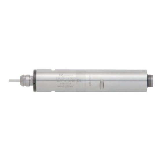
Motor Spindle
EM20- S6000 ・ EM25-S6000
EM30- S6000
OPERATION MANUAL
Thank you for purchasing Motor Spindle " EM20 - S6000・EM25 - S6000・EM30 - S6000 ". These Motor Spindles
are designed for grinding, small diameter drilling and milling, etc. The E3000 CONTROLLER and Air Line Kit are
required to drive this Motor Spindle. Read this and all the associated component Operation Manuals carefully
before use. Always keep this Operation Manual in a place where a user can referred to for reference at any time.
1.
CAUTIONS FOR HANDLING AND OPERATION
■ Read these warnings and cautions carefully and only use in the manner intended.
■ These warnings and cautions are intended to avoid potential hazards that could result in personal injury to the
operator or damage to the device. These are classi¿ed as follows in accordance with the seriousness of the risk.
Class
Degree of Risk
A safety hazard could result in bodily injury or damage to the
WARNING
device if the safety instructions are not properly followed.
A hazard that could result in light or moderate bodily injury or
CAUTION
damage to the device if the safety instructions are not followed.
WARNING
① This Motor Spindle is not a hand tool. It is designed to be used on CNC machines or special
purpose machines.
② Do not touch the cutting tool while it is running. It is very dangerous.
③ Wear safety glasses, dust mask, and use a protective cover around the Motor Spindle whenever
the Motor Spindle is rotating.
④ Never connect, disconnect or touch the Power Cord Plug or Motor Cord Plug with wet hands. This
may cause an electric shock.
⑤ Never operate or handle the Motor Spindle until you have thoroughly read the Operation Manuals
and safe operation has been con¿rmed.
1)To prevent injuries / damages, check the Motor Spindle and cutting tool for proper installation,
before operating the Motor Spindle.
2)Before disconnecting the Motor Spindle, always turn the control power off and turn the
compressed air supply to the CONTROLLER off. Then it is safe to remove the Motor Spindle.
⑥ When installing a Motor Spindle to a ¿xed base, make sure the ¿xed base is grounded in order to
avoid the risk of an electric shock.
⑦ When installing a tool, tighten the collet chuck correctly and check again the collet chuck and
chuck nut before use. Do not over-tighten the collet chuck. This may cause damage to the spindle.
⑧ Do not use bent, broken, chipped, out of round or sub-standard tools, as this may cause them to
shatter or explode. Tools with fractures or a bent shank will cause injury to the operator. When
using a new tool, rotate it in a low speed and increase speed gradually for safety.
⑨ Do not exceed the maximum recommended allowable tool speed. For your safety, use speeds
below the maximum allowable speed.
⑩ Do not apply excessive force. This may cause tool slippage, tool damage, injury to the operator or
loss of concentricity and precision.
CAUTION
① Do not drop or hit this Motor Spindle, as shock can damage to the internal components.
② Be sure to clean the collet chuck and chuck nut, the inside of the spindle before replacing the tool.
If ground particles or metal chips stick to the inside of spindle or the collet chuck, damage to the
collet chuck or spindle can occur due to the loss of precision.
③ When cleaning a Motor Spindle, stop the Motor Spindle and remove debris with a soft brush or a
cloth. Do not blow air into the dust proof cover area (refer to section " 6 - 2 Outside View ") with
compressed air as foreign particles or cutting debris may get into the ball bearing.
④ Always clean the tool shank before installing the tool in the spindle.
⑤ When sizing the correct collet chuck size to the tool shank diameter, a tolerance of +0 〜 - 0.01mm
is strongly recommended.
A tool shank within the +0 〜 - 0.1mm range is mountable, however, this may cause poor
concentricity and or insuf¿cient tool shank gripping force.
⑥ Select suitable products or tools for all applications. Do not exceed the capabilities of the
Motor Spindle or tools.
⑦ Do not stop the supply cooling air for Motor Spindle during operation of the machine.
Removing the air pressure from the Motor Spindle causes a loss of purging, allowing the Motor
Spindle to ingest coolant. This will cause damage to the Motor Spindle.
⑧ Carefully direct coolant spray to the tool. Do not spray directly on the Motor Spindle body. If large
amount spray directly on the Motor Spindle, it may cause excess load of the motor rotation with
loss of durability to the Motor Spindle.
⑨ Stop working immediately when abnormal rotation or unusual vibration are observed. Immediately,
please check the content of section " 13. TROUBLESHOOTING ".
⑩ Always check if the tool, collet chuck, chuck nut, connection hose and supply air / oil hose for
damaged before and after operating.
⑪ If the collet chuck or chuck nut show signs of wear or damage, replace them before a malfunction
or additional damage occurs.
⑫ After installation, repair, initial operation, or long periods of non operation, please refer to section
" 11. BREAK-IN PROCEDURE " detailed in Table. 4. When checking the Motor Spindle, no vibration
or unusual sound should be observed during rotation.
⑬ Do not disassemble, modify or attempt to repair this Motor Spindle. Additional damage will occur
to the internal components. Service must be performed by NSK NAKANISHI or an authorized
service center.
⑭ When using this Motor Spindle for mass production, please consider the purchase of an additional
Motor Spindle to be used as a back-up in case of emergency.
⑮ Securely connect the compressor supply connection hose and the air hose to the Air Line Kit and
the Motor Spindle to avoid accidental disconnection during use.
2.
BASIC PACKAGE
When opening the package, check if it includes all items listed in " Table. 1 Packing List Contents ".
In the event of any shortage, please contact either NAKANISHI (see the " 4. CONTACT US " section) or your local
dealer.
Table. 1 Packing List Contents
Motor Spindle・・1pc.
Inspection Card・・1pc.
OM-K0449E
004
EM20 - S6000 / EM25 - S6000
Collet Chuck
3.0mm (CHA - 3.0) or
Chuck Nut (CHN - A)・・1pc.*
3.175mm (CHA - 3.175)・・1pc.*
(For U.S. market
3.175mm
(CHA - 3.175))
Collet Chuck
3.0mm (CHK - 3.0) or
Chuck Nut (K - 265)・・1pc.*
3.175mm (CHK - 3.175)・・1pc.*
(For U.S. market
3.175mm
(CHK - 3.175))
3.
WARRANTY
We provide a limited warranty for our products. We will repair or replace the products if the cause of failure is due to
the following manufactures defects. Please contact us or your local distributor for details.
① Defect in manufacturing.
② Any shortage of components in the package.
③ Where damaged components are found when initially opening the package.
(This shall not apply if the damage was caused by the negligence of a customer.)
4.
CONTACT US
For your safety and convenience when purchasing our products, we welcome your questions.
If you have any questions about operation, maintenance and repair of the product, please contact us.
Contact Us
Contact Us
For U.S. Market
Company Name
:
Industrial Div.
Business Hours
: 8:30am to 17:00pm (CST)
(closed Saturday, Sunday and Public Holidays)
U.S. Toll Free No.
: 800-585-4675
Telephone No.
: 847-843-7664
Fax No.
: 847-843-7622
Web Address
: www.nskamericacorp.com
For Other Markets
Company Name
:
Business Hours
: 8:00am to 17:00pm
(closed Saturday, Sunday and Public Holidays)
Telephone No.
: +81 (0) 289-64-3520
e-mail Address
: webmaster-ie@nsk-nakanishi.co.jp
5.
FEATURES
① The Motor Spindle housing is made from precision ground, hardened, stainless steel (SUS) with an outside
diameter of
20mm,
25mm and
30mm.
② Excellent durability and high reliability are obtained by using a high-speed brushless motor, which eliminates
the need for brush replacement and frequent maintenance.
③ Easy to be attached to NC lathe or to replace the Motor Spindle, because the connector is placed at the edge
of the motor.
④ Various sizes of collet chucks are available CHA 0.5mm - 4.0mm or CHK 0.5mm - 6.0mm.
Standard collet chuck is 3.0mm (CHA / CHK) or 3.175mm (CHA / CHK). (For U.S. market 3.175mm (CHA /
CHK)).
6.
SPECIFICATIONS AND DIMENSIONS
6 - 1 Speci¿cations
Model
EM20 - S6000
Maximum Motor Rotation Speed
60,000min
Spindle Accuracy
Less than 1 m
Outside diameter
20mm
Max. Output
250W
Weight
230g
Noise Level at 1m distance
Less than 70dB (A)
Temperature
Operation Environment
0 - 40°C
Transportation and Storage
-10 - + 50°C
Environment
<Option>
Motor Cord *Note 1
Length : 4m, 6m, 8m
(The Air Hose (
Collet Chuck (CHA - □□ )
0.5mm -
(EM20 - S6000 / EM25 - S6000)
Collet Chuck (CHK - □□ )
0.5mm -
(EM30 - S6000)
4.76mm,
*Note1 :Motor Cord is sold separately. Please select the suitable motor cord length for your application.
Common
Operation Manual・・1set
Inspection Card
OPERATION MANUAL
Wrench (8 x 5), (9 x 11)・・ 1pc. Each.
EM30 - S6000
Wrench (12 x 14)・・2pcs.
* The collet chuck and chuck nut are attached to the Motor Spindle.
EM25 - S6000
EM30 - S6000
-1
(rpm)
25mm
30mm
350W
375g
575g
Humidity
Atmospheric Pressure
MAX.75%
700 - 1,060hPa
(No condensation)
10 - 85%
500 - 1,060hPa
4mm) of the same length is attached.)
4.0mm in 0.1mm increments and
2.35mm,
3.175mm
6.0mm in 0.1mm increments and
2.35mm,
3.175mm,
6.35mm
6 - 2 Outside View
① EM20 - S6000
Dust Proof Cover Area
11.5
58
(75)
(14.7)
133
(156)
Fig. 1
② EM25 - S6000
Dust Proof Cover Area
11.5
64
(75.5)
(14.7)
139.5
(162.5)
Fig. 2
③ EM30 - S6000
Dust Proof Cover Area
68
12.5
(81.5)
(17.4)
149.5
(175.2)
Fig. 3
6 - 3 Torque Characteristics
① EM20 - S6000 / EM25 - S6000
9
Torque
8
7
6
Output
5
4
3
2
Continuous Duty Area
1
0
10
20
30
40
50
Speed (x 10
3
min
-1
)(rpm)
Fig. 4
② EM30 - S6000
9
8
Torque
7
6
5
Output
4
3
2
Continuous Duty Area
1
0
10
20
30
40
50
60
Speed (x10
3
min
-1
)(rpm)
Fig. 5
7.
CHANGING THE TOOL
CAUTION
Do not tighten the collet chuck without inserting a tool or dummy bur, as this will damage the collet
chuck, spindle or chuck nut, causing dif¿culty removing the collet chuck.
RECOMMENDATION
Please set the cutting tools to minimize the overhang amount. 13mm is the maximum amount of
overhang to maintain high accuracy and safety.
① Set the provided wrench (EM20 - S6000 / EM25 - S6000 : 8mm, EM30 - S6000 : 12mm) on the spindle.
② Place the provided wrench (EM20 - S6000 / EM25 - S6000 : 11mm, EM30 - S6000 : 14mm) on the chuck nut
and turn it counterclockwise to loosen the collet chuck and remove the tool (The ¿rst turn will loosen the chuck
nut, but thetool will not release and turning will become stiff. Keep turning through the stiffness and thecollet
chuck will open).
③ Clean the collet chuck and chuck nut, then insert the new tool and tighten the collet chuck by turning clockwise.
Do not overtighten.
Tool
Chuck Nut
Spindle Shaft
Fig. 6
(8.3)
(8.3)
(8.3)
450
400
350
300
250
200
150
100
50
0
60
450
400
350
300
250
200
150
100
50
0
Loosen
Tighten
Advertisement

Related Manuals for Nakanishi EM20-S6000


Summary of Contents for Nakanishi EM20-S6000
- Page 1 When opening the package, check if it includes all items listed in " Table. 1 Packing List Contents ". ① EM20 - S6000 In the event of any shortage, please contact either NAKANISHI (see the " 4. CONTACT US " section) or your local EM20- S6000 ・ EM25-S6000 Dust Proof Cover Area dealer.
- Page 2 NAKANISHI's Motor Spindle is installed. ・ Cautions when tightening the securing bolts on to a Split Type Holder NAKANISHI offers Motor Spindle with a wide variety of capabilities and speci¿cations. Do not over-tighten the bolt. This will cause damage to Motor Spindle's ecision.
Need help?
Do you have a question about the EM20-S6000 and is the answer not in the manual?
Questions and answers