Advertisement
Quick Links
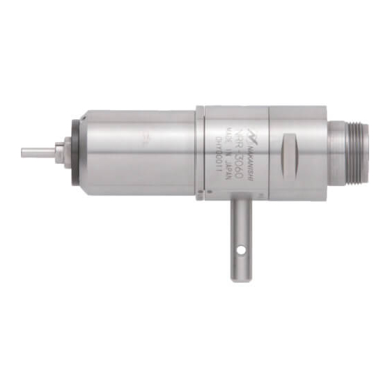
Lever Type Spindle
NRR-3060
OPERATION MANUAL
Thank you for purchasing the Lever Type Spindle " NRR - 3060 ". This Spindle has a simple lever operated
collet. No wrenches are required for tool changing. This Spindle is designed for cutting PC boards. The E3000
CONTROLLER, Brushless Motor, and Air Line Kit are required to drive this Spindle. Read this and all the associated
component Operation Manuals carefully before use. Always keep this Operation Manual in a place where a user
can referred to for reference at any time.
1.
CAUTIONS FOR HANDLING AND OPERATION
■ Read these warnings and cautions carefully and only use in the manner intended.
■ These warnings and cautions are intended to avoid potential hazards that could result in personal injury to the
operator or damage to the device. These are classi ed as follows in accordance with the seriousness of the risk.
Class
Degree of Risk
A safety hazard could result in bodily injury or damage to the
WARNING
device if the safety instructions are not properly followed.
A hazard that could result in light or moderate bodily injury or
CAUTION
damage to the device if the safety instructions are not followed.
WARNING
① This Spindle is not a hand tool. It is designed to be used on CNC machines or special purpose
machines.
② Do not touch the cutting tool while it is running. It is very dangerous.
③ Wear safety glasses, dust mask, and use a protective cover around the Spindle whenever the
Spindle is rotating.
④ Never connect, disconnect or touch the Power Cord Plug or Motor Cord Plug with wet hands. This
may cause an electric shock.
⑤ Never operate or handle the Spindle and brushless motor until you have thoroughly read the
Operation Manuals and safe operation has been con rmed.
1) To prevent injuries / damages, check the Spindle, brushless motor and cutting tool for proper
installation, before operating the Spindle and brushless motor.
2) Before disconnecting the Spindle and brushless motor, always turn the control power off and
turn the compressed air supply to the CONTROLLER off. Then it is safe to remove the Spindle
and brushless motor.
⑥ When installing a Spindle to a xed base, make sure the xed base is grounded in order to avoid
the risk of an electric shock.
⑦ Stop the brushless motor prior to operating the lever. If lever operation is performed during
spindle rotation, contact with internal components will damage the spindle.
⑧ Make sure that lever position is LOCK before rotating with mounting cutting tool.
⑨ When installing a tool, tighten the collet correctly and check again the collet before use. Do not
over-tighten the collet. This may cause damage to the spindle.
⑩ Do not use bent, broken, chipped, out of round or sub-standard tools, as this may cause them to
shatter or explode. Tools with fractures or a bent shank will cause injury to the operator. When
using a new tool, rotate it in a low speed and increase speed gradually for safety.
⑪ Do not exceed the maximum recommended allowable tool speed. For your safety, use speeds
below the maximum allowable speed.
⑫ Do not apply excessive force. This may cause tool slippage, tool damage, injury to the operator or
loss of concentricity and precision.
CAUTION
① Do not drop or hit this Spindle, as shock can damage to the internal components.
② Do not connect this Spindle to the reduction gear. This may cause collet breakage by overload.
③ Be sure to clean the collet, the inside of the spindle before replacing the tool. If ground particles
or metal chips stick to the inside of spindle or the collet, damage to the collet or spindle can occur
due to the loss of precision.
④ When cleaning a Spindle, stop the brushless motor and remove debris with a soft brush or a
cloth. Do not blow air into the dust proof cover area (refer to section " 6 - 2 Outside View ") with
compressed air as foreign particles or cutting debris may get into the ball bearing.
⑤ Always clean the tool shank before installing the tool in the spindle.
⑥ When sizing the correct collet size to the tool shank diameter, a tolerance of +0 〜 - 0.01mm is
strongly recommended.
A tool shank within the +0 〜 - 0.1mm range is mountable, however, this may cause poor
concentricity and or insuf cient tool shank gripping force.
⑦ Select suitable products or tools for all applications. Do not exceed the capabilities of the Spindle
or tools.
⑧ Do not stop the supplied cooling air to the brushless motor during operation of the machine.
Removing the air pressure from the brushless motor causes a loss of purging, allowing the
Spindle to ingest coolant and debris. This will cause damage to the Spindle.
⑨ Carefully direct coolant spray directly on the tool. Do not spray directly on the Spindle body. If
large amount spray directly on the Spindle, it may cause excess load of the Spindle rotation with
loss of durability to the Spindle.
⑩ Stop working immediately when abnormal rotation or unusual vibration are observed. Immediately,
please check the content of section " 14. TROUBLESHOOTING ".
⑪ Always check if the tool, collet are damaged before and after operating.
⑫ If the collet show signs of wear or damage, replace it before a malfunction or additional damage
occurs.
⑬ After installation, repair, initial operation, or long periods of non operation, please refer to section
" 13. BREAK-IN PROCEDURE " detailed in Table. 2. When checking the Spindle, no vibration or
unusual sound should be observed during rotation.
CAUTION
⑭ Do not disassemble, modify or attempt to repair this Spindle. Additional damage will occur to the
internal components. Service must be performed by NSK NAKANISHI or an authorized service
center.
⑮ When using this Spindle for mass production, please consider the purchase of an additional
Spindle to be used as a back-up in case of emergency.
2.
BASIC PACKAGE
When opening the package, check if it includes all items listed in " Table. 1 Packing List Contents ".
In the event of any shortage, please contact either NAKANISHI (see the " 4. CONTACT US " section) or your local
OM-K0539E
003
dealer.
Table. 1 Packing List Contents
Spindle・・1pc.
Collet
4.0mm (CHB - 4.0) ・・1pc.*
(For U.S. market
(CHB - 3.175))
Wrench (6.1 x 8)・・2pcs.
Inspection Card・・1pc.
3.
WARRANTY
We provide a limited warranty for our products. We will repair or replace the products if the cause of failure is due to
the following manufactures defects. Please contact us or your local distributor for details.
① Defect in manufacturing.
② Any shortage of components in the package.
③ Where damaged components are found when initially opening the package.
(This shall not apply if the damage was caused by the negligence of a customer.)
4.
CONTACT US
For your safety and convenience when purchasing our products, we welcome your questions.
If you have any questions about operation, maintenance and repair of the product, please contact us.
Contact Us
Contact Us
For U.S. Market
Company Name
:
Industrial Div.
Business Hours
: 8:30am to 17:00pm (CST)
(closed Saturday, Sunday and Public Holidays)
U.S. Toll Free No.
: 800-585-4675
Telephone No.
: 847-843-7664
Fax No.
: 847-843-7622
: www.nskamericacorp.com
Web Address
For Other Markets
Company Name
:
Business Hours
: 8:00am to 17:00pm
(closed Saturday, Sunday and Public Holidays)
Telephone No.
: +81 (0) 289-64-3520
e-mail Address
: webmaster-ie@nsk-nakanishi.co.jp
5.
FEATURES
① The Spindle housing is made from precision ground, hardened, stainless steel (SUS) with a mounting outside
diameter of
26.8mm.
② Various sizes of collets are available CHB - 2.0mm, 3.0mm, 3.175mm and 4.0mm. Standard collet is CHB -
3.175mm or CHB - 4.0mm (For U.S. market CHB - 3.175mm).
③ This spindle features a lever type chucking system, which facilitates the replacement of the tool by lever
rotation.
3.175mm (CHB - 3.175) or
Wrench (22 x 27)・・1pc.
3.175mm
Operation Manual・・1set
Inspection Card
OPERATION MANUAL
*The collet is attached to the Spindle.
6.
SPECIFICATIONS AND DIMENSIONS
6 - 1 Speci cations
Model
NRR - 3060
Maximum Motor Rotation Speed
60,000min
-1
(rpm)
Applicable Motor
*This Spindle can not use the
EM- 3060, EM - 3060J, EM - 3030J
reduction gear.
Milling Capacity
*Note 1
End Mill Size : Less than
1.0mm
(Cutting or Milling PC boards with
Work : PC board (ex. Glass Epoxy Resin)
an end mill)
Thickness : Less than 1.6mm
f : Less than 5,000mm / min
Weight
350g
Noise Level at 1m distance
Less than 70dB (A)
*Note 1 : You may need to lower feed rate (mm / min) depending on the shape of tools being used or the thickness
of work. Always check the milling condition before working.
Temperature
Humidity
MAX.75%
Operation Environment
0 - 40°C
(No condensation)
Transportation and Storage
-10 - 50°C
10 - 85%
Environment
<Option>
Collet (CHB- □□ )
2.0mm,
3.0mm,
3.175mm,
6 - 2 Outside View
8.5
6.9
※
30
(2.6)
(2.4)
(33.6)
20
38.8
(40.7)
(5.5)
79.5
Fig. 1
7.
CONNECTION OF THE SPINDLE TO THE MOTOR
CAUTION
Make sure your hands and all interlocking parts of the brushless moto and Spindle are clean before
connecting the Spindle to the brushless motor. This is critical in preventing contaminants from
entering the Spindle or brushless motor.
Align the thread on the front end of the brushless motor and the rear of the Spindle, and turn the Spindle clockwise.
If the drive shaft of the brushless motor does not engage properly to the drive dog on the Spindle, it may only
turn approximately two threads before stopping. DO NOT FORCE THEM TOGETHER. Loosen the Spindle from
the brushless motor, rotate the Spindle shaft by hand then re-try. The drive shaft and the drive dog must be fully
engaged. When fully engaged, secure the brushless motor and Spindle using the provided 27mm wrench (Fig. 2).
Transmission Clutch
27
Fig. 2
Atmospheric Pressure
800 - 1,060hPa
500 - 1,060hPa
4.0mm
※Dust Proof Cover Area
13
Tighten
Turn
Advertisement

Subscribe to Our Youtube Channel
Related Manuals for Nakanishi NRR-3060


Summary of Contents for Nakanishi NRR-3060
- Page 1 Thickness : Less than 1.6mm OPERATION MANUAL In the event of any shortage, please contact either NAKANISHI (see the " 4. CONTACT US " section) or your local f : Less than 5,000mm / min OM-K0539E dealer.
- Page 2 Apply working force and check that the Spindle is tight before using. designer of the equipment in which NAKANISHI's Spindle is installed. NAKANISHI offers Spindle with a wide variety of capabilities and speci cations. RECOMMENDATION ① When mounting a Spindle, refer to the Clamping Please carefully check the Spindle's speci cations against the requirements of your equipment (33.6)
Need help?
Do you have a question about the NRR-3060 and is the answer not in the manual?
Questions and answers