
Subscribe to Our Youtube Channel
Related Manuals for Nakanishi AL-H1207F


Summary of Contents for Nakanishi AL-H1207F
- Page 1 エアーラインキット / Air Line Kit AL - H1207F 取 扱 説 明 書 / OPERATION MANUAL 日本語:P1 - P10 / English:P13 - P22 OM-K0656...
-
Page 2: Cautions For Handling And Operation
Thank you for purchasing the Air Line Kit " AL - H1207F ". This Air Line Kit is designed to adjust the air ow supply and provide automatic oil mist lubrication to the air tool and reducer. An air motor, reducer, attachment, foot control "... -
Page 3: Basic Package
When opening the package, check if it includes all items listed in " Table.1 Packing List Contents ". In the event of any shortage, please contact either NAKANISHI (see the " 4. CONTACT US " section) or your local dealer. -
Page 4: Warranty
Telephone No. : +81 (0) 289-64-3520 e-mail Address : webmaster-ie@nsk-nakanishi.co.jp 5 . FEATURES ① The Filter Regulator traps small amounts of water and impure substances from the input air supply. This Air Line Kit is not intended to be used or replace an Air Dryer. -
Page 5: Specifications
6 . SPECIFICATIONS Model AL - H1207F Primary Air Pressure Less than 1.0MPa (145psi) Secondary Air Pressure Less than 0.85MPa (123.3psi) Maximum Operation Pressure 1.0MPa (145psi) Maximum Peak Pressure Less than 1.5MPa (217.6psi) Maximum Peak Pressure at Hose Connection Less than 1.0MPa (145psi) Filtration of the Filter Regulator Primary Side Air Pressure : 0.7MPa (101.5psi) Maximum Air Volume Allowed... -
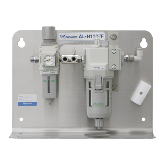
Page 6: Parts Names
7 . PARTS NAMES Control Valve Chip Air Adjusting Valve Regulator Knob Adjusting Dome ① Filter Regulator Oil Filter Cap Secondary Joint ( 6 One Touch Joint) Connection Hose Primary Joint Connector for Air Hose ② Lubricator Pressure Gauge Tool Holder Oil Reservoir Fig. -
Page 7: Operation
8 . OPERATION 8 - 1 Filter Regulator (Fig. 2) (1) Regulator Section (Fig. 2) Regulator Knob < Lock and Release of the Regulator Knob > Regulator Knob is equipped with Lock mechanism. Release Release : Pull the Regulator Knob OUT to unlock. H : Increased L : Decreased Lock... - Page 8 8 - 3 Lubricator (Fig. 4) CAUTION ・ Make sure to turn the compressed air supply to the Air Line Kit is OFF, before replacing the Lubricating Oil or draining the water in Lubricating Oil. ・ Check the Lubricating Oil level everyday and before use. If Lubricating Oil level is low, Fill the oil bowl with Lubricating Oil up to the Upper Oil Limit on the bowl.
- Page 9 9 . INSTALLATION AND CONNECTION OF THE AIR LINE KIT CAUTION The Air Line Kit install to the horizontal. If " Rear Mounting ", install the Air Line Kit to the horizontally on a vertical wall. 9 - 1 Installation of the Air Line Kit (1) Horizontal Installation When the Air Line Kit is mounted from the bottom in a horizontal position Af x the Rubber Pads (Standard Accessories : 4pcs.) to the bottom of the Air Line Kit.
- Page 10 9 - 2 Connecting the Air Motor (Fig. 8) (1) Connect the Filter Joint of the air motor to the Secondary Joint ( 6 One - Touch Joint) on the Air Line Kit. (2) Place " Exhaust Air Silencer / Oil Hose " into an empty container.(Exhaust outlet air and oil from the Siliencer.) * If using the ROTUS AIR MOTOR "...
-
Page 11: Troubleshooting
9 - 5 Operating Procedure (1) Supply air pressure to the Air Line Kit. (2) Press the Foot Control to start air motor rotation. Turn the Regulator Knob to adjust to the proper air pressure for the air motor. (3) Adjust the Oil Drip Rate to the recommended volume which is 1 to 3 drops / min (Refer to P19 " 8 - 3 (3) Adjustment of Oil Drip Rate (Fig. - Page 13 2016 .XX.XX XXX S...
Need help?
Do you have a question about the AL-H1207F and is the answer not in the manual?
Questions and answers