
Subscribe to Our Youtube Channel
Related Manuals for Nakanishi NRR4040-QC


Summary of Contents for Nakanishi NRR4040-QC
- Page 1 クイックチェンジスピンドル / Quick Change Spindle NRR4040-QC 取扱説明書 / OPERATION MANUAL 日本語 : P1 - P14 / English : P17 - P32 OM-K0640...
-
Page 2: Table Of Contents
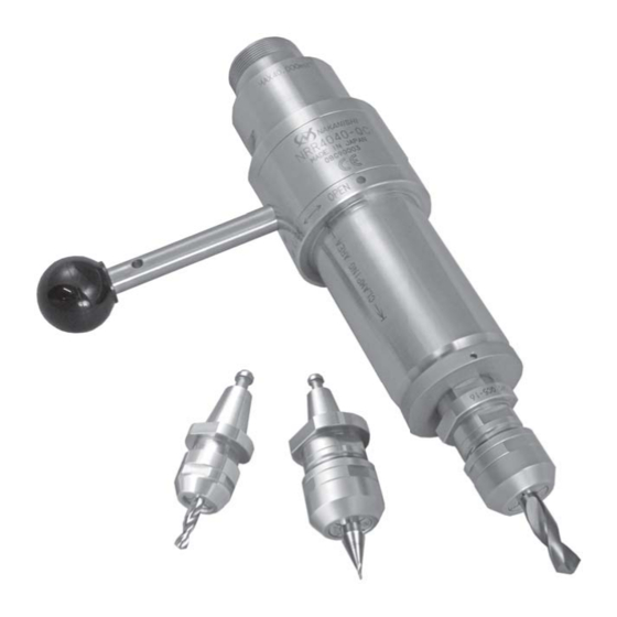
Thank you for purchasing the NRR4040-QC Quick Change Spindle. This spindle features easy replacement of the collet holder in the spindle by lever operation. The spindle is designed for grinding, small diameter drilling and milling, etc.. The <E4000 CONTROLLER>, <E4000 Series Brushless Motor>, and <Air Line Kit> are required to drive this spindle. -
Page 3: Cautions For Handling And Operation
1 . CAUTIONS FOR HANDLING AND OPERATION ■ Read these warnings and cautions carefully and only use in the manner intended. ■ These warnings and cautions are intended to avoid potential hazards that could result in personal injury to the operator or damage to the device. These are classified as follows in accordance with the seriousness of the risk. - Page 4 WARNING ⑩ Do not use bent, broken, chipped, out of round or sub-standard tools, as this may cause them to shatter or explode. Tools with fractures or a bent shank will cause injury to the operator. When using a new tool, rotate it in a low speed and increase speed gradually for safety.
-
Page 5: Features
Do not disassemble, modify or attempt to repair this spindle. Additional damage will occur to the internal components. Service must be performed by NSK NAKANISHI or an authorized service center. ⑬ When using this spindle for mass production, please purchase the another spindle as a spare in case of an emergency. - Page 6 <Option> Collet Holder QC5 - K QC5 - 16 CHK - □□ CH16 - □□ 0.5mm - 6.0mmin 0.1mm 3.0mm, 3.175mm, 4.0mm, Collet Chuck increments and 2.35mm, 6.0mm, 6.35mm, 8.0mm 3.175mm and 6.35mm and 10.0mm Chuck Nut K - 265 CHN - 16 12 ×...
-
Page 7: Changing The Tool And Replacing The Collet Chuck
4 . CONNECTION OF THE SPINDLE TO THE MOTOR CAUTION ・ Make sure your hands and all interlocking parts of the spindle and motor are clean before connecting the motor to the spindle. This is critical to prevent contaminants from entering the motor or spindle. ・... - Page 8 RECOMMENDATION Please minimize the tool overhang amount to maintaining high accuracy. 5 - 1 How to replace collets chuck using the provided wrenches ① Attach the chuck to the chuck nut. Be sure to fully engage the latch inside the chuck nut to the groove on the collet chucks outer circumference area.
- Page 9 5 - 2 Tool replacement using a preset adapter ① Affix the preset adapter to the tool holder ( 20mm) etc. ② Align the collet holder to the drive dog notch of the preset adapter, and insert the collet holder. (Fig. 8) ③...
-
Page 10: Replacing The Collet Holder
6 . REPLACING THE COLLET HOLDER CAUTION When replacing the collet holder, be sure to stop the spindle. If the lever is operated while the spindle is rotating, the spindle will incur internal damage. ① Stop the spindle rotation and confirm the rotation has stopped. ②... -
Page 11: Installation Of The Spindle
7 . INSTALLATION OF THE SPINDLE WARNING Whenever connecting a spindle to an electric motor, or when installing a spindle to a fixed base, ensure that the fixed base is grounded in order to avoid risk of an electric shock. CAUTION ・... - Page 12 ② When installing a spindle to the holder, recommended installation method is shown Fig 15. Refer to " ③ How to fabricate the Split Type Holder ". If this is not possible, install as shown in Fig. 16. Slit of Bushing Fastening Bolt Fastening Bolt Fastening Bolt...
- Page 13 ・ The final responsibility for ensuring holder's safety for use in a given application is left to the designer of the equipment in which NAKANISHI's spindle is installed. NAKANISHI offers spindles with a wide variety of capabilities and specifications. Please carefully check the spindle's specifications against the requirements of...
-
Page 14: Break-In Procedure
8 . BREAK-IN PROCEDURE During transportation, storage or installation, the grease inside the bearings will settle. If the spindle is suddenly run at high-speed, the grease will be ejected from the bearings, causing excessive heat that will cause bearing damage. After installation, repair, initial operation, or long periods of non operation, please follow the break-in procedure detailed in Table 1. -
Page 15: Cautions When Using Grindstones And Tools
9 . CAUTIONS WHEN USING GRINDSTONES AND TOOLS CAUTION The maximum surface speed or rpm is always specified for a grindstone. Do not exceed the maximum speed with reference to the calculating chart below. Always follow the grindstone manufacturer's recommendations. 3.14 x Diameter (mm) x Rotation Speed (min Surface Speed (m / s) = 1,000 x 60... -
Page 16: Troubleshooting
Cause inspection / Corrective Action Spindle does not The spindles bearings have Replace the ball bearings. rotate or rotate been damaged. (Return to NAKANISHI dealer smoothly. service.) The motor has been Replace the motor. damaged. (Return to NAKANISHI dealer service.) Lever position is OPEN. - Page 17 Cause inspection / Corrective Action Inside of the spindle is worn. Replace the spindle shaft. High run-out. (Return to NAKANISHI dealer service.) Contaminants inside the collet Clean the collet chuck, chuck chuck, chuck nut and collet nut and collet holder or the holder or the spindle.
- Page 19 12.10.20 002...
Need help?
Do you have a question about the NRR4040-QC and is the answer not in the manual?
Questions and answers