
Related Manuals for Nakanishi AL-M1202


Summary of Contents for Nakanishi AL-M1202
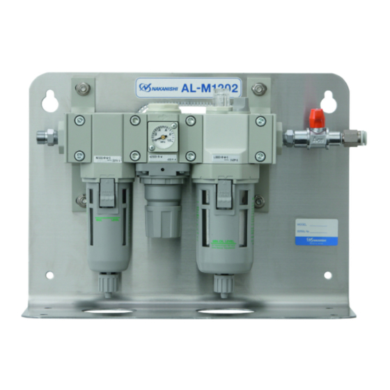
- Page 1 / Air Line Kit エアーラインキット AL - M1202 / OPERATION MANUAL 取 扱 説 明 書 日本語:P1 - P9 / English:P11 - P19 OM-K0651...
-
Page 2: Cautions For Handling And Operation
Thank you for purchasing the Air Line Kit " AL - M1202 ". This Air Line Kit is designed to adjust the air supply ow and provide oil mist automatic lubrication to the air tool and reducer. An air motor, reducer, spindle and compressor are required along with this Air Line Kit. -
Page 3: Basic Package
When opening the package, check if it includes all items listed in " Table. 1 Packing List Contents ". In the event of any shortage, please contact either NAKANISHI (see the " 4. CONTACT US " section) or your local dealer. -
Page 4: Warranty
Telephone No. : +81 (0) 289-64-3520 e-mail Address : webmaster-ie@nsk-nakanishi.co.jp 5 . FEATURES ① The Air Filter traps small amounts of water and impure substances from the input air supply. This Air Line Kit is not intended to be used or replace an Air Dryer. -
Page 5: Specifications
6 . SPECIFICATIONS Model AL - M1202 Primary Air Pressure Less than 1.0MPa (145psi) Secondary Air Pressure Less than 0.85MPa (123.3psi) Maximum Operation Pressure 1.0MPa (145psi) Maximum Peak Pressure Less than 1.5MPa (217.6psi) Maximum Peak Pressure at Hose Connection Less than 1.0MPa (145psi) Filtration of the Air Filter 0.3μm Primary Side Air Pressure : 0.7MPa (101.5psi) -
Page 6: Parts Names
7 . PARTS NAMES ② Regulator Adjusting Dome Pressure ① Air Filtar Gauge Oil Filter Cap ON / OFF Valve Connection Hose Secondary Joint Primary Joint 6 One - Touch Joint Connector for Air Hose ③ Lubricator Oli Reservoir Bowl Regulator Knob Fig. -
Page 7: Operation
8 . OPERATION 8 - 1 Air Filter (Fig. 2) The water, dirt and debris are separated from the compressed air. The separated debris is collected in the Bowl. 8 - 2 Draining (Fig. 2) Opening and closing the Drain Valve. Upper Limit (DO NOT allow liquids and / or debris to exceed the Upper Limit as shown in Fig. - Page 8 8 - 4 Lubricator (Fig. 4) CAUTION Make sure to turn the compressed air supply to the Air Line Kit is OFF, before replacing the ・ Lubricating Oil or draining the water in Lubricating Oil. Check the Lubricating Oil level everyday and before use. If Lubricating Oil level is low, Fill the oil ・...
- Page 9 9 . INSTALLATION AND CONNECTION OF THE AIR LINE KIT CAUTION The Air Line Kit install to the horizontal. If " Rear Mounting ", install the Air Line Kit to the horizontally on a vertical wall. 9 - 1 Installation of the Air Line Kit (1) Horizontal Installation When the Air Line Kit is mounted from the bottom in a horizontal position Af x the Rubber Pads (Standard Accessories : 4pcs.) to the bottom of the Air Line Kit.
-
Page 10: Troubleshooting
10 . TROUBLESHOOTING If a problem or concern occur, please check the following items prior to consulting your dealer. Trouble Inspection / Corrective Active Broken connection hose and supply Replace the connection hose and supply air / oil hose. air / oil hose. No air ow. - Page 11 2016.XX.XX XXX...
Need help?
Do you have a question about the AL-M1202 and is the answer not in the manual?
Questions and answers