
Subscribe to Our Youtube Channel
Related Manuals for Nakanishi NRR3060-QC


Summary of Contents for Nakanishi NRR3060-QC
- Page 1 クイックチェンジスピンドル / Quick Change Spindle NRR3060-QC 取扱説明書 / OPERATION MANUAL 日本語 : P1 - P14 / English : P17 - P31 OM-K0628 002...
-
Page 2: Table Of Contents
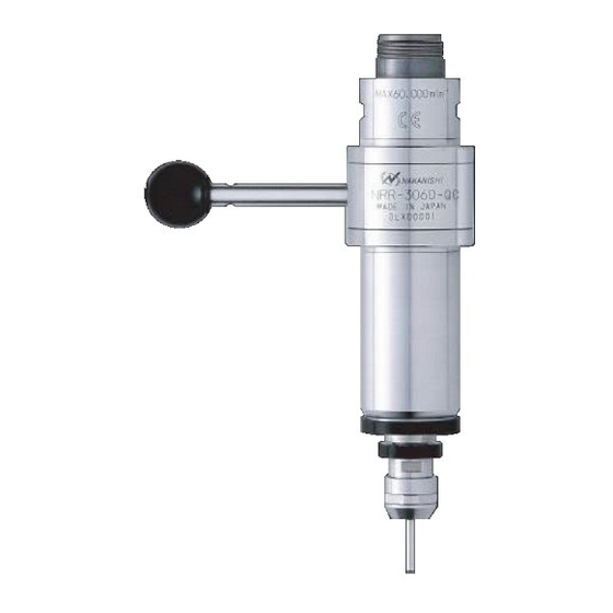
Thank you for purchasing the Quick Change Spindle " NRR3060 - QC ". This Spindle is designed for grinding, small diameter drilling and milling, etc. The E3000 CONTROLLER and Air Line Kit, brushless motor are required to drive this Spindle. Read this and all the associated component Operation Manuals carefully before use. - Page 3 WARNING ⑥ Never operate or handle the Spindle and brushless motor until you have thoroughly read the Operation Manuals and safe operation has been con rmed. 1) To prevent injuries / damages, check the Spindle, brushless motor and cutting tool for proper installation, before operating the Spindle and brushless motor.
-
Page 4: Basic Package
When opening the package, check if it includes all items listed in " Table. 1 Packing List Contents ". In the event of any shortage, please contact either NAKANISHI (see the " 4. CONTACT US " section) or your local dealer. -
Page 5: Warranty
(closed Saturday, Sunday and Public Holidays) Telephone No. : +81 (0) 289-64-3520 e-mail Address : webmaster-ie@nsk-nakanishi.co.jp FEATURES ① This Spindle features a lever type chucking system, which facilitates the replacement of the collet holder by lever rotation. ② The spindle housing is made from precision ground, hardened, stainless steel (SUS) with a mounting outside diameter of 30mm. -
Page 6: Specifications And Dimensions
SPECIFICATIONS AND DIMENSIONS 6 - 1 Speci cations Model NRR3060 - QC Maximum Motor Rotation Speed 60,000min (rpm) Spindle Accuracy Less than 1μm Lever Rotation - Rotation Angle 90° Applicable Motor EM - 3060, EM - 3060J, EM - 3030J * This Spindle can not use the reduction gear. -
Page 7: Connection Of The Spindle To The Motor
CONNECTION OF THE SPINDLE TO THE MOTOR CAUTION ・ Make sure your hands and all interlocking parts of the Spindle and brushless motor are clean before connecting the Spindle to the brushless motor. This is critical in preventing contaminants from entering the Spindle or brushless motor. ・... - Page 8 RECOMMENDATION Please set the cutting tools to minimize the overhang amount. 13mm is the maximum amount of overhang to maintain high accuracy and safety. 8 - 1 How to replace collets using the provided wrenches (1) Attach the collet to the collet nut. Be sure to fully engage the latch inside the collet nut to the groove on the collets outer circumference area (Fig.
-
Page 9: Replacing The Collet Holder
8 - 2 Tool replacement using a preset adapter (1) Af x the preset adapter to the tool holder ( 20mm) etc. (2) Align the collet holder to the drive dog notch of the preset adapter, and insert the collet holder (Fig. 8). (3) Attach the collet and collet nut to the collet holder, and lightly nger tighten (Do not tighten until the end) (Fig. - Page 10 (4) When installing the collet holder into the Spindle using an automatic tool changer (and other machines), set the collet holder a distance of 1.0 - 1.5mm from the face of the Spindle. 1.0 - 1.5 (2.9) 1.0 - 1.5 (2.9) Mountiong Mountiong...
-
Page 11: Installation Of The Spindle
INSTALLATION OF THE SPINDLE WARNING When installing a Spindle to a xed base, make sure the xed base is grounded in order to avoid the risk of an electric shock. CAUTION ・ When installing a Spindle, do not hit, drop or cause shock to the Spindle. This may cause damage to internal components and result in malfunctions. - Page 12 (2) When installing a Spindle to the holder, recommended installation method is shown Fig. 16. Refer to " (3) How to fabricate the Split Type Holder ". If this is not possible, install as shown in Fig. 17. Slit of Bushing Fastening Bolt Fastening Bolt Fastening Bolt...
- Page 13 ・ The nal responsibility for ensuring holderʼs safety for use in a given application is left to the designer of the equipment in which NAKANISHI's Spindle is installed. NAKANISHI offers Spindle with a wide variety of capabilities and speci cations. Please carefully check the Spindle's speci cations against the requirements of your...
-
Page 14: Break-In Procedure
BREAK-IN PROCEDURE During transportation, storage or installation, the grease inside the bearings will settle. If the Spindle is suddenly run at high-speed, the grease will be ejected from the bearings, causing excessive heat that will cause bearing damage. After installation, repair, initial operation, or long periods of non operation, please follow the break-in procedure detailed in Table. -
Page 15: Troubleshooting
Spindle does not rotate The Spindle ball bearings Replace the ball bearings. or rotate smoothly. have been damaged. (Return to NAKANISHI dealer service.) The motor has been Replace the motor. damaged. (Return to NAKANISHI dealer service.) Lever position is OPEN. -
Page 16: Disposal Of The Spindle
Replace the collet, collet nut or collet collet holder are worn. holder. Inside of the Spindle is worn. Replace the Spindle shaft. (Return to NAKANISHI dealer service.) Contaminants inside the Clean the collet, collet nut and collet holder collet, collet nut and collet or the spindle. - Page 17 2015 . 12 . 18 001...
Need help?
Do you have a question about the NRR3060-QC and is the answer not in the manual?
Questions and answers