
Summary of Contents for Vix Assure Adept Validator
- Page 1 Assure Adept Validator Installation Guide Document Number: DPU-00084 Revision: Revision Date: 23 Jun 2022...
- Page 2 Vix IP Pty Ltd. This material is also confidential and may not be disclosed in whole or part to any third party nor used in any manner whatsoever other than for a purpose expressly consented to by Vix IP Pty Ltd in writing.
- Page 3 Document History REVISION REVISION DESCRIPTION AUTHOR DATE 14 Jun 2021 Initial Draft. Atul Sharma 27 July 2021 Updated with review comments. Atul Sharma 13 Dec 2021 Updated document template; Carrie Huang Restructured document; Added more instructions. 15 Dec 2021 Formal Release Atul Sharma 03 Mar 2022 Added info on accessories (re)placement;...
-
Page 4: Table Of Contents
Contents Safety Precautions ....................7 Warnings and Cautions..........................7 EMC and Safety Standards Applied ......................7 1.2.1 FCC RF Radiation Exposure Statement ....................7 1.2.2 FCC Compliance Statement ........................8 1.2.3 ISED Compliance Statement ........................8 Safety ................................ 9 Introduction ......................10 Purpose .............................. - Page 5 Figure 13: Adept Validator Positioning – Height ......................24 Figure 14: Adept Validator Preferred Pole Mounting Bracing ..................25 Figure 15: Assure Adept Validator Cradle Kit ......................25 Figure 16: 3 Cradle Main Parts ........................... 26 Figure 17: Cradle Front Placement..........................27 Figure 18: Joining Cradle Front and Cradle Rear .......................
- Page 6 Figure 38: Dimensions and Weight..........................38 Figure 39: Pole Cut-out ............................... 39 Tables Table 1: Valid Devices ..............................11 Table 2: Terminology ..............................11 Table 3: Power Supply Specification .......................... 12 Table 4: Cable Connection Mapping .......................... 17 Table 5: Mating Female Connector Housings 1 & 2 ....................19 Table 6: Mating Female Crimps for Connectors 1 &...
-
Page 7: Safety Precautions
1 Safety Precautions This document presents important information that is intended to ensure the safe and effective use of this device. Please read this information carefully and store it in an accessible location near your installation. 1.1 Warnings and Cautions Warnings and cautions are used to call attention to potential hazards. -
Page 8: Fcc Compliance Statement
Any Changes or modifications not expressly approved by the party responsible for compliance could void the user's authority to operate the equipment. 1.2.2 FCC Compliance Statement This equipment has been tested and found to comply with the limits for a Class B digital device, pursuant to part 15 of the FCC Rules. -
Page 9: Safety
1.3 Safety All installation work must be carried out in accordance with State and Federal Safety Codes and Codes of Practice as well as recognized industry standards. The appropriate protective clothing must be worn where necessary. Tools must be used in accordance with manufacturers’ instructions and suitable for the task. Personnel attempting to perform any work on the electrical wiring must be trained and suitably qualified in the appropriate electrical codes of practice and must work in accordance with those codes. -
Page 10: Introduction
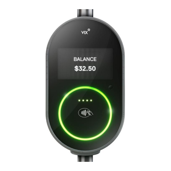
2 Introduction 2.1 Purpose This document describes the Adept Validator installation for general and expanded use. Figure 1: Picture of Adept Validator 2.2 Scope This document details the recommended installation for the Adept Validator. It describes the mechanical and electrical interfaces and how to interconnect the Adept Validator into the target environment. This document defines some of the system interfaces but does not provide in depth details, description is limited to function and potential use. -
Page 11: References
Adept with QR + Full COMMs (WIFI/GPS/4G/Bluetooth) ADEPT-AADx Adept without QR 2.3 References The following materials are to be used in conjunction with or are referenced by this document. DPU-00089 Assure Adept Validator Maintenance Manual 2.4 Glossary/Acronyms Table 2: Terminology TERM DEFINITION... -
Page 12: Installation Overview
3 Installation Overview 3.1 System Architecture Figure 2: Adept Validator Typical System Architecture 3.2 Power Supply Adept Validator can be powered either by Power-Over-Ethernet or by 24V DC power supply. Table 3: Power Supply Specification PARAMETER MIN. TYP. MAX. UNIT Input Supply Voltage Specified Input Current on power-up (@24V) Specified Input Current steady state (@24V) -
Page 13: Installation Example
3.3 Installation Example Mechanically the Adept Validator is mounted in two ways: 1. Onto a pole with a cradle. Figure 3: Picture of a Pole-Mounted Adept Validator 2. Onto a surface (e.g. Gates at train stations or TVMs (ticket vending machine)). Figure 4: Picture of a Surface-Mounted Adept Validator Refer to 6.7 for the details of the cut-out required on the surface. -
Page 14: Accessories
4 Accessories 4.1 SAMs / SIM / uSD Prior to installation, if the SAMs or SIM or uSD card need to be inserted or replaced, the Adept Validator needs to be opened by removing the 6 screws at the rear of the unit. Refer to [1] for details on how to obtain access to the main board/peripheral board. -
Page 15: Back-Up Battery
4.2 Back-up Battery The rechargeable battery on the main board provides backup power to the real time clock when the unit is disconnected from the main power. The battery usually comes with 90% charge when new, and it gets charged further during production testing, so it should be sufficient to power the RTC for approximately half a year, when out of the factory. -
Page 16: Wiring And Terminations
The following drawing shows an Adept Validator installed in isolation, with only general reference to external devices. The example diagram is mainly for the Adept Validator end only, any interconnection and extension between the Adept Validator and the terminal end needs to be discussed and confirmed between the customer and VIX. 1-WIRE_GND 1-Wire Assembly... -
Page 17: Table 4: Cable Connection Mapping
Adept Validator end to ensure EMC performance. The recommendation is Laird Technologies # 28A0593-0A2 (shown in the above diagram), but any ferrite with similar impedance characteristics and size could be submitted to VIX for approving its use. Note: The ferrites could be offset in position to accommodate for the space constraint within the pole. -
Page 18: Connector Termination
CABLE ADEPT END END TERMINATION PIN NAME CONN EXT_GPO_1 EXT_GPO_2 EXT_IN_0V Molex # 39012040 + suitable crimps EXT_GPO_ISO EXT_IN_H_1 EXT_IN_H_2 USB_OTG_P USB_OTG_ID USB type A jack USB_OTG_N Molex # VBUS_OTG 5016462000 (Optional) DIAG_RX232 (Diagnostic RS232) DB9 female DIAG_TX232 (Diagnostic RS232) DIAG_GND (Diagnostic RS232) XCVR_GND... -
Page 19: Figure 9: Rf Connector Kit
Both pole-mounted and surface-mounted Adept Validators use the same rear connectors with the same pinouts. In most installations only one connector (26WAY) is required to be terminated onto the cable. The second connector (20WAY) and the third connector (GPS) will be required only if external GPIO/USB/RS485/GPS etc. are required in the installation. -
Page 20: Circuit Breakers
For a 24V system, the recommended circuit breaker rating is 2A for the power in and 1A for remote on/off high. 5.4 Cable Recommendations VIX recommends using the following cables for the Adept Validator end. Cables between the interconnections and the end terminal/devices should be chosen appropriately, depending on the distances and current ratings. -
Page 21: Power Supply Cable
CABLE ID DESCRIPTION FUNCTION CAT5e Cable, 24AWG Stranded Shielded For CAT5e, Belden # CAT6a Cable, 24AWG Stranded Shielded (to ensure 1300SB Or Ethernet 1Gbit on 100m cable and EMC performance) Madex # For PoE application, a minimum of 24 AWG is required CAT5E-SFTP- to support the temperature rise. -
Page 22: Hierarchy For Power Supply
5.5.2 Hierarchy for Power Supply Figure 11 shows a typical wiring hierarchy for the equipment power supply cabling in the automotive vehicle environment. Notice that the cable ratings are higher than the circuit breakers and fuse ratings. In this example the circuit breaker rating has been de-rated to 70% of the cable maximum continuous current rating. -
Page 23: Current Capacity
Table 10: Cable Length DISTANCE FROM START POINT CONDUCTOR SIZE EQUIVALENT CABLE 0m-20m 20 AWG Belden 9408 (2 Conductors) 20m-40m 18 AWG Belden 9409 (2 Conductors) 40m-50m 16 AWG Belden 9410 (2 Conductors) Note: The highest rated cable (Belden 9410) can be used in all situations. 5.5.4 Current Capacity The maximum continuous current rating for a cable is limited by conductor size, number of conductors contained... -
Page 24: Pole Mounting
6 Pole Mounting This pole mounting process requires no tool, except a key (for unlocking the lock if needed), providing the pole has already been cut out as required. Refer to Appendix C for the cut-out required on the mounting pole. This includes a cut-out for the cables and a cut- out for the locating pin. -
Page 25: Cradle Kit
The cradle components are delivered as a kit (CRADLE-ADEPT-x-Ryy) designed for a standard 32mm pole. Note: If a different diameter pole is to be used, the size needs to be informed to VIX prior to order so that available accessories could be recommended. For a 30mm or 35mm pole, extra parts could be obtained from VIX to suit: CRADLE-KIT-30 or CRADLE-KIT-35. -
Page 26: Cradle Mounting Instructions
To prepare for installation, the cradle has to be disassembled into the below three main parts – cradle front, cradle rear and external cover, by following steps 2 to 4 in section 6.6. External cover with 4x seals The locating pin is a fixed component of the cradle front. -
Page 27: Figure 17: Cradle Front Placement
Figure 17: Cradle Front Placement 4. Insert the 4 pins on the cradle rear into the 4 holes on the cradle front. Press the 2 halves together, they should lock into place with a click. Figure 18: Joining Cradle Front and Cradle Rear 5. -
Page 28: Figure 19: Correct And Incorrect Position Of Closed Cradle Arms
Figure 19: Correct and Incorrect Position of Closed Cradle Arms 6. Check the cradle is secure on the pole. If not, undo the arms and insert the supplied small shims at the indicated location (on both sides), then close the arms and check again. Small shim, colour may vary Figure 20: Adept Validator Cradle Mount Shims 7. -
Page 29: Figure 21: Seals Position On External Cover
Figure 21: Seals Position on External Cover 8. Wrap the cover around the cradle sub-assembly from the back and clip it in place. Figure 22: Adept Validator Cradle Mount Cover 9. Feed the cables through the protective rubber boot to provide environmental protection. Ensure there is sufficient slack for the Adept Validator connection and mounting. -
Page 30: Validator Mounting Instructions
Protective rubber boot Cable Figure 23: Rubber Boot Installation 6.4 Validator Mounting Instructions Check that the Adept Validator casing has no corners, sharp edges, or exposed fixings (nuts/bolts) that may present a hazard to personnel. 1. Carefully connect the cables to the rear of the Adept Validator, including the GPS cable for an Adept Validator model with GPS. -
Page 31: Figure 25: Adept Validator Mounting On Cradle
3. Press the lock button to secure the device in place on the cradle. Note: By default, the lock button is on the right of the cradle viewing from the front, if the left side is preferred, inform VIX prior to order. Figure 26: Device Locking Note: Once the device is locked in place, a key is required to unlock it from the cradle. -
Page 32: Validator Demounting Instructions
6.5 Validator Demounting Instructions Caution: The unit connectors present a low risk of accidental short circuit or electric shock if the unit is removed when powered, hence it is recommended the power is turned off prior to disconnection. 1. Unlock the cradle lock by pushing in the key slightly and rotating anti-clockwise or clockwise until the lock button bounces out. -
Page 33: Cradle Demounting Instructions
Figure 29: Cable Disconnection Note: Care must be taken not to damage the cables/connectors during unit removal. 6.6 Cradle Demounting Instructions 1. Carefully remove the rubber boot from the cables. Note: Care must be taken not to damage the cables/connectors during rubber boot removal. Figure 30: Rubber Boot Removal 2. -
Page 34: Figure 31: External Cover Removal
Figure 31: External Cover Removal 3. Open both cradle mount flaps. Figure 32: Opening Cradle Arms 4. Remove the cradle rear from the cradle front by pressing the indicated metal part (on both sides) to release the 4 pins. Note: One may prefer to do this step on one side at a time. -
Page 35: Figure 33: Cradle Front And Rear Separation
Press Pull Figure 33: Cradle Front and Rear Separation 5. Remove the cradle front by carefully pulling it out from the pole. Note: Care must be taken not to damage the cables/connectors during cradle front removal. Figure 34: Cradle Front Removal DPU-00084 Page 35 of 39 Revision 2.3... -
Page 36: Cradle Covering
The cradle cover could be obtained from VIX with the part number being PROD1000-x. 1. Cover the cradle by aligning the three locating plates, pushing forward, then pushing down to clip in as shown below. -
Page 37: Appendix A Cut-Out For Surface Mount Adept Validator
Appendix A Cut-out for Surface Mount Adept Validator Details of cut-out required for surface mounting the Adept Validator are shown below. Figure 37: Cut-out for Surface Mount Adept Validator DPU-00084 Page 37 of 39 Revision 2.3... -
Page 38: Appendix B Dimensions And Weight
Appendix B Dimensions and Weight Pole mounted Adept Validator’s physical dimension are approximately 160mm(w) x 278mm(h) x 59mm(d), without cradle. Unit’s weight is approximately 1.5 kg, without cradle. Figure 38: Dimensions and Weight DPU-00084 Page 38 of 39 Revision 2.3... -
Page 39: Appendix C Pole Cut-Out
Appendix C Pole Cut-out Recommended cut-out for the pole is shown below. Figure 39: Pole Cut-out DPU-00084 Page 39 of 39 Revision 2.3...
Need help?
Do you have a question about the Assure Adept Validator and is the answer not in the manual?
Questions and answers