Table of Contents
Advertisement
Visual Holding Cabinet
(MHA, MHD, MHG, MHL, MHS, MHT)
Original Instructions
Installation, Operation and Maintenance Manual
This manual is updated as new information and models are released. Visit our website for the latest manual.
*8197701*
Part Number: MER_IOM_8197701 10/2021
Original Instructions
CAUTION
READ THE INSTRUCTIONS BEFORE USING THE CABINET.
Keep these instructions for future reference.
Serving Quality on Demand
Advertisement
Table of Contents

Related Manuals for Welbilt Merco MHA


Summary of Contents for Welbilt Merco MHA
- Page 1 Serving Quality on Demand Visual Holding Cabinet (MHA, MHD, MHG, MHL, MHS, MHT) Original Instructions Installation, Operation and Maintenance Manual This manual is updated as new information and models are released. Visit our website for the latest manual. CAUTION *8197701* READ THE INSTRUCTIONS BEFORE USING THE CABINET.
- Page 2 Safety Notices Warning Use caution when handling metal surface edges of all Warning equipment. Read this manual thoroughly before operating, installing or performing maintenance on the equipment. Failure Warning to follow instructions in this manual can cause property This appliance is not intended for use by children damage, injury or death.
- Page 3 NOTICE This appliance is intended to be used for commercial applications, for example in kitchens of restaurants, canteens, hospitals and in commercial enterprises such as bakeries, butcheries, etc., but not for continuous mass production of food. Warning DO NOT use water jets or a steam cleaner to clean this equipment or installed in an area where a water jet can be used NOTICE...
-
Page 4: Table Of Contents
Table of Contents Section 1 General Information Model Numbers .......................1-1 Serial Number Information ....................1-1 Warranty Information .....................1-1 Regulatory Certifications ....................1-1 Section 2 Installation Location ...........................2-1 Weight of Equipment ......................2-2 Clearance Requirements ....................2-2 Dimensions ........................2-2 Electrical Service ......................2-2 Voltage ..............................2-2 Rated Voltage, Cycles, Phases, Wattage, Amperages & Power Cord Chart ....2-3 Section 3 Operation Power Switch ........................3-1... - Page 5 Table of Contents (continued) Section 5 Troubleshooting Troubleshooting Chart ....................5-1...
-
Page 6: General Information
Section 1 General Information Model Numbers Visit http://www.mercoproducts.com/Service#Warranty to: • Register your product for warranty. Models Description • Verify warranty information. (X)MHG22SAT1W 2x2 - Front Display • View and download a copy of your warranty. (X)MHG22SAT2W 2x2 Front and Rear Display Regulatory Certifications (X)MHS22SAT1W 2x2 - Front Display... - Page 7 General Information Section 1 This device complies with Industry Canada’s license-exempt RSSs. Operation is subject to the following two conditions: (1) This device may not cause interference; and (2) This device must accept any interference, including interference that may cause undesired operation of the device.
-
Page 8: Installation
Section 2 Installation Location DANGER Installation must comply with all applicable fire and Warning health codes in your jurisdiction. This equipment must be positioned so that the plug is accessible unless other means for disconnection from DANGER the power supply (e.g., circuit breaker or disconnect Carts must be installed and the carts must be screwed switch) is provided. -
Page 9: Weight Of Equipment
Installation Section 2 Weight of Equipment Models Width Depth Height 16.2” 22.5” 23.8” Models Weight (X)MHD42SSL1T (41.1cm) (57.2cm) (60.5cm) (X)MHG22SAT1W/2W 50lbs (23kg) 20.8” 22.5” 32.0” (X)MHD82SST1T (X)MHS22SAT1W 50lbs (23kg) (52.8cm) (57.2cm) (81.3cm) (X)MHG23SAT1W/2W 120lbs (54kg) Electrical Service (X)MHL24SSL1T 120lbs (54kg) (X)MHG32SAT1W/2W 62lbs (28kg) DANGER... -
Page 10: Rated Voltage, Cycles, Phases, Wattage, Amperages & Power Cord Chart
Section 2 Installation RATED VOLTAGES, CYCLES, PHASES, WATTAGE, AMPERAGES & POWER CORD CHART Units with plugs are supplied with approximately 6ft cords. Model Voltage, Cycle, Phase Watts Amps Plug MHG22SAT1W/2W 120V, 60H, 1Ph 1920 16.0 5-20P MHS22SAT1W 120V, 60H, 1Ph 1330 11.1 5-15P... -
Page 11: Operation
Section 3 Operation The Merco Visual Holding Cabinet has been designed to DANGER afford food service operators the ability to cook menu The on-site supervisor is responsible for ensuring that components in advance and then gently store that product operators are made aware of the inherent dangers of in the holding bins until an order is received. -
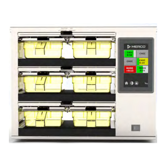
Page 12: User Interface
Operation Section 3 User Interface The unit will beep signaling that all holding zones are pre- heated and ready for use. PASSWORD • A user can access all necessary screens for daily operation without a password. • The factory default manager password is 2580. PRESS &... - Page 13 Section 3 Operation The green portion of the tray timer represents the The alarm will beep for 10 seconds. The timer will display remaining time. Each menu item has a programmed time the product is being held past programmed hold time. warning time.
-
Page 14: Tray Tracking
Operation Section 3 TRAY TRACKING Press & Hold Transfer (Manual) To manually transfer a food item to an empty holding position, press and hold the empty position for ~2 seconds. The following pop-up screen will display (if the manual transfer is not completed within a few seconds, it will revert back to the previous timers and locations). -
Page 15: Tray Specifications
Section 3 Operation TRAY SPECIFICATIONS A Group in the Menu Use First For Identical Products A product in the menu is part of a group if there are dots underneath it or arrow heads on either side of it. Select the When two identical products are active, the one with the menu item with the dots and the other items in the group least time remaining will be highlighted in green, the others... - Page 16 Operation Section 3 On press and go screen the lock icon disables the touch screen for 10 seconds. The lock icon must be held for 1 second to disable the screen. In the center of the lock graphic the 10 seconds will be counted down. Ten seconds of disabled screen allows time for the touch screen to be cleaned.
-
Page 17: Menu Screens
Section 3 Operation MENU SCREENS Select the unwanted product and then the delete icon, X. A confirmation widow will pop up. Select the green check to From the home screen selecting the menu icon brings up delete the product. Select the red X to return to the menu the menu screen. - Page 18 Operation Section 3 On the menu screen are navigation icons. If the group page is unlocked, the delete, edit and add icons will display on the group screen. • The first icon returns you to the product list screen. • The second takes you to the group list screen .
- Page 19 Section 3 Operation Select the group to be edited and the edit icon, a pencil. In To add a group, select the group page add icon, +. A pop up the pop up window the group will appear. You can edit the window will appear.
-
Page 20: Usb Screen
Operation Section 3 On the menu screen are navigation icons. Next to the back USB SCREEN arrow is the day part edit icon. From the home screen selecting the USB icon brings up the USB screen. A passcode needs to be entered to upload a new menu file. -
Page 21: Setting Screens
Section 3 Operation SETTINGS SCREENS PREFERENCES SCREEN From the home screen selecting the settings icon brings up the preferences screen. This is the first of eleven setting screens. There are eleven solid dots across the bottom of the service screens, the empty circle represents the current page. -
Page 22: Date & Time Screen
Operation Section 3 DATE & TIME SCREEN LANGUAGE SCREEN To make changes on the this screen a passcode must be entered. Select the lock on the bottom left of the screen. Enter a passcode on the pop-up number pad. If the passcode is accepted there will be a yellow ring around the screen. -
Page 23: Cabinet Names Screen
Section 3 Operation CABINET NAMES SCREEN (USED ONLY IN LOCATIONS NETWORKING SCREENS WITH MULTIPLE CABINETS AND OPTIONAL TRAY To make changes on the this screen a passcode must be TRACKING) entered. Select the lock on the bottom left of the screen. To make changes on the this screen a passcode must be Enter a passcode on the pop-up number pad. -
Page 24: Zone Diagnostics Screens
Operation Section 3 To connect the Holding Cabinet to the local WiFi check both ZONE DIAGNOSTICS SCREENS the Enable box and the DHCP box, then touch the box just Holding cabinet temperatures can be monitored on this to the right of SSID. That will open a new window that will screen, no password is required to observe current heating allow the name and password of the WiFi network to be element temperatures. -
Page 25: Errors Log Screen
Section 3 Operation ERRORS LOG SCREEN PASSWORD SETTINGS SCREEN This screen does not require a passcode. Errors Log Screen Password Settings Screen Clear all button removes all entries on the errors log screen. There is a factory default manager passcode. It can be Touching the Refresh button will update the error changed on the password service screen. -
Page 26: System Information Screen
Operation Section 3 SYSTEM INFORMATION SCREEN This screen does not require a passcode, there are no actions available on this screen. Utilities Screen A service passcode is required to enter the advanced utilities menu. System Information Screen Demo Mode Enabled – to run demo mode, a service This screen lists the cabinet serial number, model number passcode must be entered. - Page 27 Section 3 Operation to complete the action. (Import function from this screen is ONLY used to upload a menu file from another cabinet, NOT to upload a file from the MenuConnect online menu creation application). To upload a MenuConnect created menu file, please use the USB icon from the Home screen.
-
Page 28: Maintenance
Section 4 Maintenance Cleaning and Sanitizing Procedures DANGER All utility connections and fixtures must be maintained GENERAL in accordance with Local and national codes. You are responsible for maintaining the equipment in accordance with the instructions in this manual. DANGER Maintenance procedures are not covered by the warranty. -
Page 29: Interior Cleaning
Maintenance Section 4 INTERIOR CLEANING DAILY CLEANING INSTRUCTIONS 1. You will need a damp cloth and hot soapy water. Caution 2. Turn the unit off. Do not use caustic cleaners on any part of the holding cabinet or holding cabinet cavity . Use mild, non abrasive soaps or detergents, applied with a sponge or soft cloth. - Page 30 Section 4 Maintenance 6. Remove the tray seals (on some models). 10. Wipe the interior with a damp cloth; clean from the front and the back to reach all surfaces. Pay attention to the ledges that support tray seals. If an excessive amount of food particles/grease has collected, hot sudsy water (non-abrasive) may be used.
- Page 31 Section 5 Troubleshooting Troubleshooting Chart Problem Cause Correction Cabinet not running Fuse blown or circuit breaker tripped. Replace fuse or reset circuit breaker. Power cord unplugged. Plug in power cord. Main power switch turned off. Turn main power switch on. Display has cross hatch in heating Heating pad connector is loose.
- Page 32 8700 LINE AVENUE, SHREVEPORT, LA 71106-6800 MERCO SALES: 800.221.4583 MERCO SERVICE: 877.392.7770 Serving Quality on Demand WWW.MERCOPRODUCTS.COM ©2021 Welbilt Inc. except where explicitly stated otherwise. All rights reserved. Continuing product improvement may necessitate change of specifications without notice. Part Number: MER_IO_8197701 10/2021...
Need help?
Do you have a question about the Merco MHA and is the answer not in the manual?
Questions and answers