Table of Contents
Advertisement
Quick Links
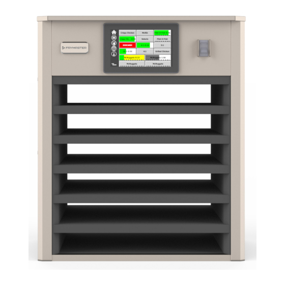
UHCTHD Touch Holding Cabinet
Original Instructions
Installation, Operation and Maintenance Manual
This manual is updated as new information and models are released. Visit our website for the latest manual.
*8197667*
Part Number: FRY_IOM_8197667 01/2020
Original Instructions
CAUTION
READ THE INSTRUCTIONS BEFORE USING THE CABINET.
Keep these instructions for future reference.
Your Growth Is Our Goal
Advertisement
Table of Contents

Related Manuals for Welbilt Frymaster UHCTHD


Summary of Contents for Welbilt Frymaster UHCTHD
- Page 1 Your Growth Is Our Goal UHCTHD Touch Holding Cabinet Original Instructions Installation, Operation and Maintenance Manual This manual is updated as new information and models are released. Visit our website for the latest manual. CAUTION READ THE INSTRUCTIONS BEFORE USING THE CABINET. Keep these instructions for future reference.
- Page 2 Safety Notices DANGER Do not install or operate equipment that has been Warning misused, abused, neglected, damaged, or altered/ Read this manual thoroughly before operating, installing modified from that original manufactured or performing maintenance on the equipment. Failure specifications. to follow instructions in this manual can cause property damage, injury or death.
- Page 3 Warning DO NOT use this product near water – for example, near a kitchen sink, in a wet basement, near a swimming pool, or similar locations. Warning DO NOT attempt to repair or replace any component of the UHCTHD unless all power to the unit has been disconnected.
-
Page 4: Table Of Contents
Table of Contents Section 1 General Information Model Numbers ....................1-1 Serial Number Information ................1-1 Service Personnel ....................1-1 Regulatory Certifications .................. 1-1 Warranty Information ..................1-1 Section 2 Installation Location ......................2-1 Weight of Equipment ..................2-2 Clearance Requirements .................. 2-2 Dimensions ...................... - Page 5 Table of Contents (continued) Section 4 Preventative Maintenance Cleaning and Preventative Maintenance Procedures ........4-1 General ....................... 4-1 Every Four (4) Hours - Clean Trays/Racks ............4-1 Daily - Clean Cabinet ..................4-1 Section 5 Troubleshooting Troubleshooting Chart ..................5-1 Appendix A Exporting/Importing Exporting/Importing Settings and Menus ............
-
Page 6: General Information
Section 1 General Information Model Numbers for a period of two years. All parts, with the exception of fuses, are Models Description warranted for two years after installation UHCTHD6 6-slot date of cabinet UHCTHD3 3-slot If any parts, except fuses, become defective during the first two years after installation Serial Number Information date, Frymaster will also pay straight-time... - Page 7 Frymaster Service Department at 1-800-551-8633 or 1-318-865- 1711. Email at fryservice@welbilt.com. Please note that orders for wire/plastic trays, stacking kits, carts and casters should be placed with your local Kitchen Equipment Supplier (KES).
-
Page 8: Installation
Section 2 Installation Location DANGER Installation must comply with all applicable fire and Warning health codes in your jurisdiction. This equipment must be positioned so that the plug is accessible unless other means for disconnection from DANGER the power supply (e.g., circuit breaker or disconnect Use appropriate safety equipment during installation switch) is provided. -
Page 9: Weight Of Equipment
Installation Section 2 Weight of Equipment Warning This appliance must be grounded and all field wiring Model Weight must conform to all applicable local and national UHCTHD6 195.6 lbs (88.7kg) codes. Refer to rating plate for proper voltage. It is the UHCTHD3 120lbs (54kg) responsibility of the end user to provide the disconnect... -
Page 10: Install Cord Hanger
Section 2 Installation Place empty food trays in all row positions Caution DO NOT position the UHCTHD near the steam or heat Install Grill Clip exhaust of another appliance. The grill clip is designed to hold the 1/3-size grill tray. Install Cord hanger It attaches to the grill to make transfer from the grill to the UHCTHD faster and... -
Page 11: Operation
Section 3 Operation The Frymaster UHCTHD Holding Cabinet has been designed DANGER to afford food service operators the ability to cook menu The on-site supervisor is responsible for ensuring that components in advance and then gently store that product operators are made aware of the inherent dangers of in the holding bins until an order is received. -
Page 12: User Interface
Operation Section 3 User Interface PRESS & GO SCREENS When the unit is turned on zone pre-heating will begin. The PASSWORD press and go screen will be displayed. • A user can access all necessary screens for daily Green operation without a password. •... -
Page 13: Tray Specifications
Section 3 Operation The numbers on the display are associated with the the product is being held past the programmed hold time. locations of the cabinet. They will be highlighted in green Tray and food should be removed. Reset the expired tray and the product timer will start. -
Page 14: Changing Day Parts
Operation Section 3 CHANGING DAY PARTS ECO MODE SCREEN The individual slots can be put into an ECO mode, which Touch the row management icon and slide left or right temporarily lowers the heating temperature, when not in across the dots, under the daypart menu selection, to choose a daypart menu by row. -
Page 15: Menu Screens
Section 3 Operation MENU SCREENS Delete a Product Select the unwanted product and then the delete icon by From the home screen selecting the menu icon brings up pressing the X button. A confirmation widow will pop up. the menu screen. Select the green check to delete the product. - Page 16 Operation Section 3 To edit a field select the field. Editing temperatures and times uses the touchpad. When finished press the return arrow to exit to last screen. Group Screen If the group page is unlocked, the delete, edit and add icons will display on the group screen.
- Page 17 Section 3 Operation • To select the default product for the group (product to Select a product for the group and the green arrow be displayed when the day part is selected), press and to add it. That first product will determine the group hold that product button for three seconds.
-
Page 18: Setting Screens
Operation Section 3 Select a hot holding zone by quickly pressing the empty • Use First – When checked the first tray of common zone to add a product or change the product. From the product will be highlighted in green, second tray will pop up window select the product to be added to the be gray until the first tray is gone or time runs out. -
Page 19: Language Screen
Section 3 Operation • Time Zone - Use the drop down box to select the time ZONE DIAGNOSTICS SCREENS zone the equipment is being used in. This only has an Holding cabinet temperatures can be monitored on this effect on the date and time setting if the Use NTP box is screen, no password is required to observe current heating checked. -
Page 20: Sound & Screen Tests
Operation Section 3 SOUND & SCREEN TESTS PASSWORD SETTINGS SCREEN This screen does not require a passcode. Password Settings Screen Sound & Screen Tests There is a factory default manager passcode 1955. It can be Screen is for testing sound and screen function. changed on the password service screen. -
Page 21: System Information Screen
Section 3 Operation SYSTEM INFORMATION SCREEN This screen does not require a passcode, there are no actions available on this screen. Utilities Screen System Information Screen This screen lists the cabinet serial number, model number and current firmware versions. UTILITIES SCREEN To run demo mode on the utility screen a service passcode must be entered. -
Page 22: Cleaning And Preventative Maintenance Procedures
Section 4 Preventative Maintenance Cleaning and Preventative Maintenance DANGER Procedures All utility connections and fixtures must be maintained in accordance with local and national codes. GENERAL You are responsible for maintaining the equipment DANGER in accordance with the instructions in this manual. Maintenance procedures are not covered by the It is the responsibility of the equipment owner to warranty. - Page 23 Maintenance Section 4 4. The unit displays COOLING DOWN while the 12. The unit displays Exit cabinet is cooling. Clean?. 13. Press the check button to exit. 14. Turn the unit off. Warning Never use a high-pressure water jet for cleaning or hose down or flood interior or exterior of units with water.
-
Page 24: Troubleshooting Chart
Section 5 Troubleshooting Troubleshooting Chart Problem Cause Correction Cabinet not running Fuse blown or circuit breaker tripped. Replace fuse or reset circuit breaker. Power cord unplugged. Plug in power cord. Main power switch turned off. Turn main power switch on. Display has cross hatch in heating Heating pad connector is loose. - Page 25 Appendix A Importing/Exporting Menus and Configurations The menus and configurations can be exported and Swipe once to the right to the Utilities screen. imported to a USB thumb drive. Settings Icon EXPORTING FILES Select the home icon to bring up the home screen. Home Icon Press the lock icon in the lower left corner.
- Page 26 Operation Appendix A 12. Press the Close button again. Slide open the USB port behind the Frymaster logo. Insert a blank USB drive into the USB port. 13. Press the unlock button in the lower left corner to lock the screen. Press the Check Flash Drive button.
- Page 27 Appendix A Operation IMPORTING FILES Follow steps 1-7 in the preceding section. Insert a USB drive with files exported from a UHCTHD cabinet into the USB port. Press the unlock button in the lower left corner to lock the screen. Press the Check Flash Drive button.
- Page 28 All of our products are backed by KitchenCare® – our aftermarket, repair, and parts service. CLEVELAND DELFIELD® FRYMASTER® KOLPAK® MANITOWOC® MERRYCHEF® CONVOTHERM® FITKITCHEN™ GARLAND LINCOLN MERCO® MULTIPLEX® ©2020 Welbilt Inc. except where explicitly stated otherwise. All rights reserved. Continuing product improvement may necessitate change of specifications without notice. Part Number: FRY_IOM_8197667 01/2020...
Need help?
Do you have a question about the Frymaster UHCTHD and is the answer not in the manual?
Questions and answers