Winmate M Series User Manual
15”/17”/19”/21.5” p-cap touchscreen, with intel atom e3845 1.91 ghz
Hide thumbs
Also See for M Series:
- User manual (112 pages) ,
- User manual (110 pages) ,
- User manual (101 pages)
Table of Contents

Related Manuals for Winmate M Series


Summary of Contents for Winmate M Series
- Page 1 M-Series HMI 15”/17”/19”/21.5” P-cap touchscreen, with Intel® Atom™ E3845 1.91 GHz Multifunctional Design R15IBWS-MHC3 Model No.: R17IBWS-MHM1 R19IBWS-MHA2 W22IBWS-MHA3 User Manual Version 1.0 Manual Part Number: 9152111I100P...
- Page 2 Preface Copyright Notice No part of this document may be reproduced, copied, translated, or transmitted in any form or by any means, electronic or mechanical, for any purpose, without the prior written permission of the original manufacturer. Trademark Acknowledgement Brand and product names are trademarks or registered trademarks of their respective owners.
- Page 3 distributor, sales representative, or our customer service center for technical support if you need additional assistance. You may need the following information ready before you call: Product serial number Software (OS, version, application software, etc.) Description of complete problem ...
- Page 4 ALTERNATING CURRENT / MISE À LE TERRE! The Protective Conductor Terminal (Earth Ground) symbol indicates the potential risk of serious electrical shock due to improper grounding. Le symbole de Mise à Terre indique le risqué potential de choc électrique grave à la terre incorrecte.
- Page 5 Safety Precautions For your safety carefully read all the safety instructions before using the device. Keep this user manual for future reference. Always disconnect this equipment from any AC outlet before cleaning. Do not use liquid or spray detergents for cleaning. Use a damp cloth. ...
- Page 6 equipment. CAUTION/ATTENTION Use the recommended mounting apparatus to avoid risk of injury. Utiliser l’appareil de fixation recommandé pour éliminer le risque de blessure. WARNING! / AVERTISSEMENT! Only use the connection cords that come with the product. When in doubt, please contact the manufacturer. Utiliser seulement les cordons d’alimentation fournis avec le produit.
- Page 7 Important Information Countries/ Area Symbol This equipment complies with essential requirements of: European Union Electromagnetic Compatibility Directive (2014/30/EU) Low Voltage Directive (2014/35/EU) Restrictions of the use of certain hazardous substances (RoHS) Directive (2011/65/EU) FCC Part 15 Subpart B Regulations Class B Federal Communications Commission Radio Frequency Interface Statement This device complies with part 15 FCC rules.
- Page 8 EC Declaration of Conformity [English] The object of the declaration described above [A] is in conformity with the requirement of the following EU legislations [B] and harmonized standards [C]. Product also complies with the Council directions [D]. [German] Das oben beschriebene Objekt [A] entspricht den Anforderungen der nachfolgend aufgeführten EU-Vorgben [B] und den harmonisierten Normen [C].
-
Page 9: Table Of Contents
Contents Preface ............................ii 1 Introduction ..........................2 1.1 Product Features ........................2 1.2 Hardware Specifications ...................... 3 1.3 Software Support ......................... 4 1.4 Packing List ........................... 5 1.4.1 Accessories ........................ 5 1.5 Appearance .......................... 6 1.6 Dimensions ........................... 7 15”... - Page 10 2.5 Adjusting the LCD Display Brightness ................18 2.6 Turning Off ......................... 18 3 Operating the Device ....................... 20 3.1 Multi-Touch ........................20 3.2 Operating System ....................... 21 4 Driver Installation ........................23 4.1 Installing Chipset Driver ..................... 23 4.2 Installing Graphics Driver ....................25 4.3 Installing Intel Sideband Fabric Device (Intel MBI) Driver (Windows 8) ......
- Page 11 7.1 Software Developer Support ..................... 54 7.1.1 Watchdog SDK ......................54 7.2 Problem Report Form ......................55 8 Certificates ..........................57 8.1 FCC Declaration of Conformity ..................57 8.1.1 R15IBWS-MHC3 ....................... 57 8.1.2 R17IBWS-MHM1 ...................... 58 8.1.3 R19IBWS-MHA2 ....................... 59 8.1.4 W22IBWS-MHA3 .....................
- Page 12 M-Series HMI Introduction Introduction This chapter gives you product overview, describes features and hardware specification. You will find all accessories that come with the HMI device in the packing list. Mechanical dimensions and drawings included in this chapter. User Manual...
-
Page 13: Introduction
M-Series HMI Introduction 1 Introduction M-Series HMI is designed to provide versatile and cost-effective solution for your industrial needs. P-cap multi-touch screen equipped with industrial motherboard offers various input/ output connectors. Intel® Atom™ E3845 1.91 GHz processor onboard with fanless cooling system assures steady performance and silent functioning. M-Series HMI perfectly fits in applications where total costs of ownership (TCO) and quick recovery of failure is important. -
Page 14: Hardware Specifications
M-Series HMI Introduction 1.2 Hardware Specifications Model Name R15IBWS-MHC3 R17IBWS-MHM1 R19IBWS-MHA2 W22IBWS-MHA3 Display: Size 15” 17” 19” 21.5” Active Display 304.1 x 228.1 337.9 x 270.3 376.32 x 301.06 476.64 x 268.11 Area (H x V) Pixel Pitch 0.297x 0.297 0.264 x 0.264 0.294 x 0.294 0.248 x 0.248... -
Page 15: Software Support
M-Series HMI Introduction Dimensions 398.16 x 330.54 x 445.72 x 370.46 x 530.5 x 322 x 367 x 291 x 80 (L x W x H) 79.6 79.6 79.2 Environmental Considerations: Operating 0 to 50°C Temperature Operating 30%~95% at 40°C (non-condensing, RH) Humidity Front: IP65 IP Rating... -
Page 16: Packing List
M-Series HMI Introduction 1.4 Packing List Carefully remove the box and unpack your HMI device. Please check if all the items listed below are inside your package. If any of these items are missing or damaged contact us immediately. 1.4.1 Accessories Standard factory shipment list: HMI Device Power Cord... -
Page 17: Appearance
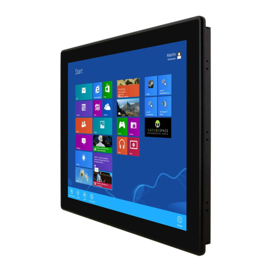
M-Series HMI Introduction 1.5 Appearance User Manual... -
Page 18: Dimensions
M-Series HMI Introduction 1.6 Dimensions 15” Dimensions User Manual... -
Page 19: 17" Dimensions
M-Series HMI Introduction 17” Dimensions User Manual... -
Page 20: 19" Dimensions
M-Series HMI Introduction 19” Dimensions User Manual... -
Page 21: Dimensions
M-Series HMI Introduction 21.5” Dimensions User Manual... - Page 22 M-Series HMI Getting Started Getting Started This chapter tells you important information on power supply, adapter and precautions tips. Pay attention to power considerations. User Manual...
-
Page 23: Getting Started
M-Series HMI Getting Started 2 Getting Started This chapter provides information on how to connect the HMI device to the source of power, connector pinouts and the guideline to turn on/off the HMI device. 2.1 Powering On 2.1.1 AC Adapter Components 1. -
Page 24: Power Considerations
M-Series HMI Getting Started Ce produit doit être mis à la terre. Utiliser seulement un cordon d’alimentation avec mise à la terre. Si les règlements locaux le requiert, installer des câbles de mise à la terre supplémentaires. *Si vous n’utiliser pas une prise d’alimentation avec mise à la terre, vous pourriez remarquer une sensation de picotement électrique quand la paume de vos mains touche à... -
Page 25: Connector Pinouts
M-Series HMI Getting Started 3. Connect the AC adapter to the power cord. 4. Plug the power cord to a working AC outlet. The device will boot automatically. Note: Power cords vary in appearance by region and country. Connecting to DC Power Source 1. -
Page 26: Audio-In (Microphone)
M-Series HMI Getting Started 2.2.2 Audio-in (microphone) Pin № Name Pin № Name Audio signal in Audio signal in 2.2.3 Audio-out (headphone) Pin № Name Pin № Name Audio signal Audio signal out, out, left channel right channel 2.2.4 COM1 Serial Port Connector Pin №... -
Page 27: Usb 2.0 Connector
M-Series HMI Getting Started 2.2.6 USB 2.0 Connector Pin № Pin № Name Name Data- Data+ 2.2.7 VGA Output Connector Pin № Name Pin № Name GREEN BLUE ID2/RES RED_RTN GREEN_RTN BLUE_RTN KEY/PWR ID0/RES ID1/SDA HSync VSync ID3/SCL 2.2.8 POE/LAN (RJ45) Connector Pin №... -
Page 28: Configuring Serial Port Com1
M-Series HMI Getting Started 2.4 Configuring Serial Port COM1 Serial COM1 can be configured for RS-232, RS-422 or RS-485. Jumpers are located on the motherboard. You need to open the housing in order to access the jumpers. CAUTION/ ATTENTION It is recommended to use factory jumper settings. Opening the housing when it is sealed may damage the device and its parts. -
Page 29: Adjusting The Lcd Display Brightness
M-Series HMI Getting Started The picture below shows RS-232/422/485 (J8/J9) jumper setting. Example: To make RS-232 Settings, set the Jumper 8 Pin 1-2 to the SHORT position, and Jumper 9 Pin1-2, 4-5, 7-8, 10-11 to the SHORT position. 2.5 Adjusting the LCD Display Brightness Tap Start >... - Page 30 M-Series HMI Operating the Device Operating the Device This chapter provides detailed information on how to operate the device. If you have been using touch-screen Panel PCs before, the interface may look familiar. Sections include system settings parameters. User Manual...
-
Page 31: Operating The Device
M-Series HMI Operating the Device 3 Operating the Device In this chapter you will find instructions on how to use multi-touch on the Windows- based HMI device. 3.1 Multi-Touch The touchpad supports the core gestures for Windows. Gesture Windows Gesture Action Action Usage Tap/... -
Page 32: Operating System
M-Series HMI Operating the Device discretion Press and Hold Right-click Press, wait for blue- ring animation to complete, then release Flicks Default: Pan Make quick drag Up/ Down/ gestures in the Back, and described direction Forward * Reference from Microsoft® 3.2 Operating System M-series HMI support several versions of Windows OS: Windows 10 IoT Enterprise, Windows Embedded 8 Standard, and Windows Embedded Standard 7 –... - Page 33 M-Series HMI Driver Installation Driver Installation This chapter describes how to install all necessary drivers. User Manual...
-
Page 34: Driver Installation
M-Series HMI Driver Installation 4 Driver Installation This chapter provides guideline to driver installations. 4.1 Installing Chipset Driver Step 1 Insert the CD that comes with the motherboard. Open the file document “Chipset Driver” and click “infinst_auto.exe” to install driver. User Manual... - Page 35 M-Series HMI Driver Installation Step 2 Click Next to continue. Step 3 Click Yes to agree the license terms. User Manual...
-
Page 36: Installing Graphics Driver
M-Series HMI Driver Installation Step 4 Click Next to install the driver. Step 5 Software setup progress window will appear, click Next to continue. Step 6 Click “Yes, I want to restart this computer now” to finish the installation. 4.2 Installing Graphics Driver Step 1 Insert the CD that comes with the motherboard. -
Page 37: Installing Intel Sideband Fabric Device (Intel Mbi) Driver (Windows 8)
M-Series HMI Driver Installation Step 3 Carefully read the license terms and click Yes to agree. Step 4 Check Readme file information, and click Next to install driver. Step 5 Click Next to continue. Step 6 Windows Security window will appear, click “Install this driver software anyway” to continue. -
Page 38: Installing Intel Trusted Engine Interface (Intel Txe) Driver
M-Series HMI Driver Installation 4.4 Installing Intel Trusted Engine Interface (Intel TXE) Driver Step 1 Insert the CD that comes with the motherboard. Open the file document “TXE” and click “Setup TXE.exe” to install the driver. Step 2 Welcome to the setup program window will appear, click Next to start the installation. -
Page 39: Installing Intel Network Connections
M-Series HMI Driver Installation 4.5 Installing Intel Network Connections User must confirm the type of operating system is being used before installing Intel Network Connections. Follow the steps below to complete the installation. Step 1 Click “PROWin64.exe” Step 2 Click Yes to start the installation. Step 3 Welcome window will appear, click Next to install the driver. -
Page 40: Installing Audio Driver
M-Series HMI Driver Installation 4.6 Installing Audio Driver The ALC886 series are high-performance 7.1+2 channel high definition audio codecs that provide ten DAC channels for simultaneous support of 7.1 sound playback, plus 2 channels of independent stereo sound output (multiple streaming) through the front panel stereo outputs. -
Page 41: Installing Usb 3.0 Driver (Windows 7)
M-Series HMI Driver Installation 4.7 Installing USB 3.0 Driver (Windows 7) NOTE: If your operation system is Windows Embedded 8.1 Industry or Windows Embedded 8 Standard, you should skip the USB 3.0 driver installation. You need to install the Intel® USB 3.0 extensible Host Controller driver to enable the function. - Page 42 M-Series HMI BIOS Setup BIOS Setup BIOS Setup Utility is a program for configuration basic Input / Output system settings of the HMI for optimum use. This chapter provides information on how to use BIOS setup, its functions and menu. User Manual...
-
Page 43: Bios Setup
M-Series HMI BIOS Setup 5 BIOS Setup 5.1 When and How to Use BIOS Setup To enter the BIOS setup, you need to connect an external USB keyboard, press <Del> key when the prompt appears on the screen during start up. The prompt screen shows only few seconds, you need to press <Del>... -
Page 44: Main Menu
M-Series HMI BIOS Setup The following Keys can be used after entering the BIOS Setup. Function General Help Previous Values Optimized Defaults Save & Exit Exit Change Opt. Enter Select or execute command Cursor ↑ Moves to the previous item Cursor ↓... - Page 45 M-Series HMI BIOS Setup BIOS Setting Description Setting Option Effect System Displays the system Adjustment of the Set the language in Language language. [English] is language other language. The set up by default. language in this device is English. System This is current date Date and time Set the date in the...
-
Page 46: Advanced Menu
M-Series HMI BIOS Setup 5.2.2 Advanced Menu The advanced menu also uses to set configuration of the CPU and other system devices. There are sub menus on the left frame of the screen. IMPORTANT: Handle advanced BIOS settings page with caution. Any changes can affect the operation of your computer. - Page 47 M-Series HMI BIOS Setup BIOS Setting Description Setting Effect options Opens ACPI Settings Configures ACPI settings Enter submenu Opens SMART Settings Configures SMART settings Enter submenu Configures System Super IO Opens Super IO Configuration Enter Chip parameters submenu Opens Hardware Monitor Monitor hardware status Enter submenu...
-
Page 48: Usb Configuration
M-Series HMI BIOS Setup Opens CMOS CMOS settings / Information Enter submenu Opens Trusting Computing Trusted computing settings Enter submenu Opens USB Configuration Configures USB settings Enter submenu Platform Trust Opens Platform trust technology Enter Technology submenu For items marked ► press <Enter> for more options. 5.2.3 USB Configuration BIOS Setting Description... -
Page 49: Chipset
M-Series HMI BIOS Setup This is a workaround Disable Disables this function EHCI Hand-off for OSs without ECHI Enable Enables this function hand-off support. User can Enable or Disable Disables this function USB mass storage disable USB mass driver support Enable Enables this function storage driver support. - Page 50 M-Series HMI BIOS Setup Chipset – North Bridge Parameters BIOS Setting Description Setting Effect options Provides onboard Opens Intel IGD Configuration graphics-related Enter submenu configuration options. Configures IGD – LCD Opens IGD – LCD Control Enter setting submenu Provides power saving Graphic Power configuration options Opens...
- Page 51 M-Series HMI BIOS Setup Chipset – South Bridge Parameters BIOS Setting Description Setting options Effect Disables this Disable function Configures onboard audio Azalia HD Audio function. Enables this Enable function Enable / USB 2.0(EHCI) Disable this function Enable / USB Port 0 Disable this Provides user with function...
- Page 52 M-Series HMI BIOS Setup PCI Express channel and Disable this speed configuration. function Enable / PCI Express port 2 Disable this function Enable / PCI Express port 3 Disable this function Disables this Disable Configures high precision function High Precision timer (HPET) in the Timer Enables this...
-
Page 53: Security
M-Series HMI BIOS Setup 5.2.5 Security Allows user to configure an administration or user password, user must enter the administrator or user password at system startup and when entering BIOS setup. BIOS Setting Description Setting Effect options Displays whether or not an Administrator Enter administrator password has... - Page 54 M-Series HMI BIOS Setup Security – Secure Boot Menu BIOS Setting Description Setting options Effect Disables this Disable function Displays the current boot Secure Boot state. Enables this Enable function Disables this Disable function Allows user to configure Secure Boot Mode the secure boot mode.
-
Page 55: Boot
M-Series HMI BIOS Setup 5.2.6 Boot BIOS Setting Description Setting Effect options Allows user to configure the Set the Setup Prompt Timeout number of seconds to stay in Enter prompt BIOS setup prompt screen. timeout Enables or disables NumLock Remains On feature on the numeric Boot NumLock State keypad of the keyboard after... -
Page 56: Save & Exit
M-Series HMI BIOS Setup hard drives, optical drives, present the floppy disk drives, and devices of the devices that support Boot same type are from LAN function. connected. 5.2.7 Save & Exit BIOS Setting Description Setting options Effect Saves the Enter <Yes>... -
Page 57: Using Recovery Wizard To Restore Computer
M-Series HMI BIOS Setup changes. Return to the Esc <No> BIOS Setup Main Menu Saves the Enter <Yes> changes Save changes done so far Save Changes to any of the setup Return to the options. Esc <No> BIOS Setup Main Menu Saves the Enter <Yes>... - Page 58 M-Series HMI BIOS Setup A warning message about data loss will show up. Make sure the data is backed up before recovery, and click Yes to continue. Wait the recovery process to complete. During the recovery process, a command prompt will show up to indicate the percent of recovery process complete. The system will restart automatically after recovery completed.
- Page 59 M-Series HMI Mounting Solutions Mounting Solutions This chapter provides step-by-step mounting guide for all available mounting options. User Manual...
-
Page 60: Mounting Solutions
M-Series HMI Mounting Solutions 6 Mounting Solutions This chapter provides mounting guide for all available mounting options. Pay attention to cautions and warning to avoid any damages. CAUTION/ ATTENTION Follow mounting instructions and use recommended mounting hardware to avoid the risk of injury. Suivez les instructions de montage et d'utilisation recommandé... -
Page 61: Mounting Guide
M-Series HMI Mounting Solutions electrical characteristics must be bundled together. • Do not bundle input wiring with output wiring. Keep them separate. When necessary, it is strongly advised that you label wiring to all devices in the system. 6.3 Mounting Guide M-series HMI devices come with different mounting options suitable for most of the industrial and commercial applications. -
Page 62: Flush Mount / Panel Mount
M-Series HMI Mounting Solutions 6.3.2 Flush Mount / Panel Mount Cutout dimension ( W x D in mm) 15” 17” 19” 21.5” 387 x 291 408 x 313 479.3 x 300.3 534 x 331 Screw hole diameter M3 x 4 mm User Manual... - Page 63 M-Series HMI Mounting Solutions Mounting Steps: Prepare a fixture for the specific dimensions of the device. Cut a hole on a sub frame or panel according to the cutout dimensions. Install the device properly onto the cutout area of the sub frame or panel with the sides of the front bezel.
- Page 64 M-Series HMI Technical Support Documents Technical Support Documents This chapter includes Technical Support Documents. User Manual...
-
Page 65: Technical Support Documents
7.1 Software Developer Support Download SDK from Winmate Download Center or Winmate Partner Portal. 7.1.1 Watchdog SDK To find the Watchdog Sample code, please refer to the driver CD SDK that comes in a package or contact us. -
Page 66: Problem Report Form
M-Series HMI Certificates 7.2 Problem Report Form M-Series HMI (Multifunctional Design) Customer name: Company: Tel.: Fax: E-mail: Date: Product Serial Number: ____________________________________________________ Problem Description: Please describe the problem as clearly as possible. Detailed description of the occurred problem will allow us to find the best solution to solve the problem as soon as possible. - Page 67 M-Series HMI Certificates Certificates This chapter includes FCC and EC Declarations of Conformity. User Manual...
-
Page 68: Certificates
M-Series HMI Certificates 8 Certificates This chapter includes FCC and EC Declarations of Conformity. 8.1 FCC Declaration of Conformity 8.1.1 R15IBWS-MHC3 User Manual... -
Page 69: R17Ibws-Mhm1
M-Series HMI Certificates 8.1.2 R17IBWS-MHM1 User Manual... -
Page 70: R19Ibws-Mha2
M-Series HMI Certificates 8.1.3 R19IBWS-MHA2 User Manual... -
Page 71: W22Ibws-Mha3
M-Series HMI Certificates 8.1.4 W22IBWS-MHA3 User Manual... -
Page 72: Ec Declaration Of Conformity
M-Series HMI Certificates 8.2 EC Declaration of Conformity 8.2.1 R15IBWS-MHC3 Refer to Preface for letters abbreviations in English and other languages. User Manual... -
Page 73: R17Ibws-Mhm1
M-Series HMI Certificates 8.2.2 R17IBWS-MHM1 Refer to Preface for letters abbreviations in English and other languages. User Manual... -
Page 74: R19Ibws-Mha2
M-Series HMI Certificates 8.2.3 R19IBWS-MHA2 Refer to Preface for letters abbreviations in English and other languages. User Manual... -
Page 75: W22Ibws-Mha3
M-Series HMI Certificates 8.2.4 W22IBWS-MHA3 Refer to Preface for letters abbreviations in English and other languages. User Manual... - Page 76 Winmate Inc. 9F, No.111-6, Shing-De Rd., San-Chung City, Taipei 241, Taiwan, R.O.C Tel: 886-2-8511-0288 Fax: 886-2-8511-0211 Email: sales@winmate.com.tw Official website: http://www.winmate.com.tw...
Need help?
Do you have a question about the M Series and is the answer not in the manual?
Questions and answers