
Related Manuals for Carlisle MS Elite M5


Summary of Contents for Carlisle MS Elite M5
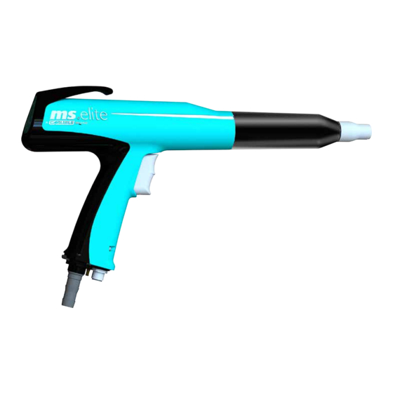
- Page 1 SERVICE MANUAL MS elite M5 Manual Powder Spray Applicator Model: 615210 2813 ll 2D 2mJ PA-17-08-R6 (02/2022) 1 / 40 www.carlisleft.com...
- Page 2 MANUAL CHANGES NOTE: This manual has been changed from revision PA-17-08-R5 to revision PA-17-08-R6. Reasons for this change are noted under “Manual Change Summary” inside the back cover of this manual. PA-17-08-R6 (02/2022) 2 / 40 www.carlisleft.com...
-
Page 3: Table Of Contents
Function ................................... 19 Nozzle Functions ..............................20 INSTALLATION: 21-26 Commissioning and Operation of MS elite M5 Manual Powder Applicator ............. 21 Safe Handling of the Manual Powder Applicator ..................... 21 Cable and Hose Connections ........................... 22 Wiring Diagram of MS elite Control Module for Vibratory Cart ................. -
Page 4: Safety
This information relates to USER SAFETY and PREVENTING and safety literature for your equipment, contact your local EQUIPMENT PROBLEMS. To help you recognize this Carlisle Fluid Technologies representative or Carlisle Fluid information, we use the following symbols. Please pay Technologies technical support. -
Page 5: Hazards / Safeguards
SAFETY Return To Contents AREA SAFEGUARDS HAZARD Tells where hazards Tells how to avoid the hazard. Tells what the hazard is. may occur. Fire Hazard Spray Area Fire extinguishing equipment must be present in the Improper or inadequate spray area and tested periodically. operation and maintenance procedures will cause a fire Spray areas must be kept clean to prevent the... - Page 6 SAFETY Return To Contents AREA SAFEGUARDS HAZARD Tells where hazards Tells how to avoid the hazard. Tells what the hazard is. may occur. Explosion Hazard Spray Area Improper or inadequate Electrostatic arcing must be prevented. Safe sparking operation and maintenance distance must be maintained between the parts being procedures will cause a coated and the applicator.
- Page 7 SAFETY Return To Contents AREA SAFEGUARDS HAZARD Tells where hazards Tells how to avoid the hazard. Tells what the hazard is. may occur. Spray Area / Electrical Discharge High Voltage There is a high voltage device Parts being sprayed and operators in the spray Equipment that can induce an electrical area must be properly grounded.
- Page 8 SAFETY Return To Contents AREA SAFEGUARDS HAZARD Tells where hazards Tells how to avoid the hazard. Tells what the hazard is. may occur. Electrical Electrical Discharge Unless specifically approved for use in hazardous Equipment locations, the power supply, control cabinet, and all High voltage equipment is utilized in the process.
-
Page 9: Intended Use
SAFETY Return To Contents INTENDED USE 1. The MS elite M5 Manual powder applicator is exclusively for Safety Regulations for Electrostatic use in powder coating. It has been developed according to Powder Coating recognized safety regulations for use in potentially explosive atmospheres according to directive RL 2014/34/EU. -
Page 10: Notice On Harmless Discharges
SAFETY Return To Contents 12. The grounding of all conductive parts (hooks, chain conveyors, etc.) must be checked at least weekly. The Resistance to earth must be less than 1 MΩ (Mega Ohm). 13. When cleaning the powder applicator and when replacing the nozzles, the controller must be switched off. -
Page 11: Safety Considerations
SAFETY Return To Contents When the high voltage is switched on, a glow or corona 2. The operator must help to ensure that no unauthorized discharge occurs at the tip. This is only visible in a dark persons work on the powder spraying device (e.g. by environment. - Page 12 SAFETY Return To Contents Crushing and shearing points Energized equipment must not be service while power is on. The power must be disconnected prior to servicing. During operation, moving parts may automatically move in the workspace. Only trained and authorized persons may Powder approach this equipment.
-
Page 13: Atex/Fm/Ukex
ATEX/FM/UKEX Return To Contents ATEX/FM/UKEX EUROPEAN ATEX DIRECTIVE 2014/34/EU, ANNEX II, UKSI 2016: 1107 (AS AMENDED) The following instructions apply to equipment covered by by suitably trained personnel in accordance with the certificate number FM 19ATEX0004X and FM21UKEX0140X: manufacturer's documentation. The equipment may be used with ignitable powders with The certification of this equipment relies upon the apparatus groups II and with temperature class T6. -
Page 14: Label
Equipment Category Type of explosive atmosphere (dust) EEx 2mJ = The MS elite M5 applicator is suitable for use in manual spraying installations complying with EN 50050-2: 2013 as it is a Type A class with a discharge energy limit of 2mJ. -
Page 15: Approvals (Atex/Fm/Ukex)
APPROVALS (ATEX/FM/UKEX) Return To Contents APPROVALS (ATEX/FM/UKEX) 615210 Base Model No. (Ordering information only) Configuration DWG. 835091, 835092, 805700 615215, 615216, 615050-3X, 615050-1X 615218 615225, 615226 615213 AVAILABLE ACCESSORIES Description Part # 615215 Extension Flat Spray F150 615216 Extension Flat Spray F300 615218 Round Spray Nozzle Set R1 615225... -
Page 16: Specifications
APPROVALS (ATEX/FM/UKEX) Return To Contents SPECIFICATIONS Dimension: Weight: 458 g (Without cable and hose assembly) (15.1 oz.) Length: 350 mm (Flat spray nozzle) (13.7 inches) Electrical Data: Frequency: 40 kHz Output voltage: 100 kV DC Maximum Output current: 110 µA Maximum Polarity: Negative Pneumatic Data:... -
Page 17: Introduction
DC charge to the electrode, creating an electrostatic field between the nozzle and the target. One of the many features of the MS elite M5 manual powder applicator is that the electrical energy, which is available from the resistive charging electrode, is limited to the optimum level of safety and efficiency. -
Page 18: Ms Elite M5 Manual Parts Breakdown
INTRODUCTION Return To Contents MS elite M5 MANUAL PARTS BREAKDOWN Item # Description Body of the applicator Operator panel Nozzle nut Flat spray nozzle Trigger Applicator cable connector Powder hose connector Applicator air inlet barb PA-17-08-R6 (02/2022) 18 / 40... -
Page 19: Function
INTRODUCTION Return To Contents FUNCTION Upon actuation of the trigger (1) (controller is turned on), the Since these particles have the same charge as the spray cascade is activated in the spray applicator. Simultaneously, applicator, they are repelled, distributed in a fine cloud and the powder supply (2) as well as the air supply (3) is activated deposited evenly on the grounded work piece. -
Page 20: Nozzle Functions
INTRODUCTION Return To Contents NOZZLE FUNCTIONS Flat fan nozzle The applicator air is used to cool the electrode in the flat spray nozzle during operation to deter impact fusion. Applicator Air High Voltage Round spray nozzle The applicator air is used to cool the electrode during operation to deter impact fusion. -
Page 21: Installation
INSTALLATION Return To Contents INSTALLATION COMMISSIONING AND OPERATION SAFE HANDLING OF THE OF MS elite M5 MANUAL POWDER MANUAL POWDER APPLICATOR APPLICATOR 1. Never point powder applicator at any person for any reason. NOTE 2. Persons with pacemakers may not at any time stand in the †... -
Page 22: Cable And Hose Connections
INSTALLATION Return To Contents CABLE AND HOSE CONNECTIONS CONNECTING Connect From Connecting to Controller Manual Powder Applicator Cable Applicator Connect Powder Applicator Controller Dosage Air Hose Doseage Air Red Controller Injector Dosage Air Feed Air Hose Feed Air Blue Controller Injector Feed Air Gun Air Hose Rinse Air Black... -
Page 23: Wiring Diagram Of Ms Elite Control Module For Vibratory Cart
INSTALLATION Return To Contents WIRING DIAGRAM OF MS elite CONTROL MODULE FOR VIBRATORY CART Vibrator Control Signals 24VDC 230/110V 50/60Hz 6 bar Inlet (87 psig) Air Pressure (max) www.carlisleft.com 23 / 40 PA-17-08-R6 (02/2022) -
Page 24: Wiring Diagram Of Ms Elite Control Module For Fluidized Hopper
INSTALLATION Return To Contents WIRING DIAGRAM OF MS elite CONTROL MODULE FOR FLUIDIZED HOPPER Vibrator Control Signals 24VDC 230/110V 50/60Hz 6 bar Inlet (87 psig) Air Pressure (max) PA-17-08-R6 (02/2022) 24 / 40 www.carlisleft.com... -
Page 25: Tubing Diagram For Use With 610190-11
INSTALLATION TUBING DIAGRAM FOR USE WITH 610190-11 Supply 6 bar Inlet (87 psig) Air Pressure (max) www.carlisleft.com 25 / 40 PA-17-08-R6 (02/2022) -
Page 26: Connecting Manual Powder Applicator
INSTALLATION Return To Contents CONNECTABLE CONTROLLERS CONNECTING MANUAL MS elite MANUAL POWDER APPLICATOR POWDER APPLICATOR The powder hose is connected via a quick disconnect. This enables a rapid plugging and unplugging of the powder hose. The MS elite manual powder spray applicator may only be The powder hose is locked into the applicator. -
Page 27: Operation
OPERATION Return To Contents OPERATION OPERATION Requirements for good grounding are: On the back of the manual powder spray applicator is a control panel. With this, the programs can be changed and • Any hangers used to suspend work pieces must be the amount of powder can be adjusted. -
Page 28: Changing Program On The Manual Powder Applicator
OPERATION Return To Contents CHANGING PROGRAM ON THE MANUAL POWDER APPLICATOR Press the arrow key to go to the Program mode The LED P lights up red when the mode is activated. The program can be changed with the +/- button. Press the At the controller module, the selected arrow key again to confirm. -
Page 29: Maintenance
POWDER APPLICATOR Removing the Nozzle CAUTION † Maintenance, repair or replacement of parts may only be performed by trained personnel of Carlisle Fluid Technologies. WA R N I N G † Wear parts in the powder applicator, marked with a W in the spare parts list, must be checked regularly and replaced if necessary. - Page 30 MAINTENANCE Return To Contents 4. Carefully pull out the nozzle tube (3) without twisting the NOTE applicator body (4). † At this stage, check to make sure conductive ring 5. Clean the removed nozzle and powder applicator with 461706 is intact. compressed air.
-
Page 31: Troubleshooting Guide
MAINTENANCE Return To Contents TROUBLESHOOTING GUIDE General Problem Possible Cause Solution Inconsistent See “Installing the Nozzle” section. Wear bar or flat spray nozzle are improperly Powder Cloud oriented No Power or Check plug connections. Improper power cord connection. Air Delivery Check cable connections. -
Page 32: Parts Identification
PARTS IDENTIFICATION Return To Contents PARTS IDENTIFICATION 615214 615258 461775 615277 615213 615260-00 615032 615258 615258 460230 461775 615277 615213 615260-00 M5 MANUAL APPLICATOR SPARE PARTS LIST Item # Description Wear Part 460230 Nozzle Nut MS elite 461775 Nozzle Tube 615213 Nozzle Holder 615032... -
Page 33: Accessories
PARTS IDENTIFICATION Return To Contents ACCESSORIES 615214 615277 615258 461775 615260-00 615213 FLAT SPRAY NOZZLES “C3” Description Part # 615214 Assembly, Flat Spray Nozzle & Electrode 615258 Assembly, Flat Spray Nozzle (Included in 615214) 460105-K5, -K25, -K50 O-Ring Nozzle Kit 615260-00, -K5 Wire Assembly Kit 615277, -K5... - Page 34 PARTS IDENTIFICATION Return To Contents 615218 460450 460430 460440 460460 615219-01 615260-00 461775 615213 ROUND SPRAY NOZZLES “R” Part # Description 615218 Round Spray Nozzle Set R1 460430 Round Spray Nozzle D16 (Included in 615218) 460440 Round Spray Nozzle D20 (Included in 615218) 460450 Round Spray Nozzle D24 (Included in 615218) 460460...
- Page 35 PARTS IDENTIFICATION Return To Contents POWDER HOSE Part # Description 810195-06 Powder Hose 6m, (10mm ID) Length = 4.8 810195-08 Powder Hose 8m, (10mm ID) Length = 6.8 810195-10 Powder Hose 10m, (10mm ID) Length = 8.8 810195-16 Powder Hose 16m, (10mm ID) Length = 14.8 810195-100 Powder Hose 100m, Bulk (10mm ID) Length = 100 810190-100...
-
Page 36: Nozzle Extensions
PARTS IDENTIFICATION Return To Contents 615215 (150mm) 615216 (300mm) 615258 615239 (150mm) 615240 (300mm) 461866 615000-150 (150mm) 615000-300 (300mm) 615212 615330-03 (150mm) 615213 615330-01 (300mm) 615258 461888 FLAT SPRAY NOZZLE EXTENSIONS “C3” Part # Description 615215 Assembly, Nozzle Extension Flat Spray Set, 150mm 615239 Assembly, Extension Tube 150mm 615000-150... - Page 37 PARTS IDENTIFICATION Return To Contents 615050-1X (150mm) 615050-3X (300mm) 615130-X 615239 (150mm) 615240 (300mm) 615000-150 (150mm) 461866 (O-RING) 615000-300 (300mm) 615330-03 (150mm) 615212 615330-01 (300mm) 615213 461888 615130-X FLAT SPRAY NOZZLE EXTENSIONS “G” Part # Description Assembly, Nozzle Extension Flat Jet Set, 150mm 615050-13 Nozzle Extension Flat Jet Set, 150mm (3mm wide) 615050-14...
- Page 38 PARTS IDENTIFICATION Return To Contents 615225 (150mm) 615226 (300mm) 615239 (150mm) 461866 (O-RING) 615213 615240 (300mm) 615219-02 (150mm) 460430 460440 460450 460460 615219-03 (300mm) 615330-04 (150mm) 615330-02 (300mm) 461888 ROUND SPRAY NOZZLE EXTENSIONS “R” Part # Description 615225 Assembly, Nozzle Extension Round Spray Set, 150mm 615239 Assembly, Extension Tube 150mm 615330-04, -K5...
-
Page 39: Manual Change Summary
INTRODUCTION Return To Contents MANUAL CHANGE SUMMARY PA-17-08-R6 - Replaces PA-17-08-R5 with the folowing changes: Change Description Page(s) New cover image and add UKCA logo Add CE EX logo to table Text updates to items 5, 9, 14 and 17 Update text in “SAFETY CONSIDERATIONS”, bullet points 6 and 9, last paragraph Correct first sentence New label, remove bullet points 1 and 2, update text in FM Configurations... - Page 40 WARRANTY POLICY This product is covered by Carlisle Fluid Technologies’ materials and workmanship limited warranty. The use of any parts or accessories, from a source other than Carlisle Fluid Technologies, will void all warranties. Failure to reasonably follow any maintenance guidance provided, may invalidate any warranty.
Need help?
Do you have a question about the MS Elite M5 and is the answer not in the manual?
Questions and answers