Table of Contents
Advertisement
Quick Links
SERVICE MANUAL
EN
Models: 79503 R90 Classic - Solventborne
IMPORTANT: Before using this equipment, carefully read SAFETY PRECAUTIONS and all
instructions in this manual. Keep this Service Manual for future reference.
AH-06-02-R16 (10/2019)
Vector
Classic Applicators
79504 R70 Classic - Solventborne
79520 R90 Classic - Waterborne
For Use With 80130-XXX 9060 Power Supply
R Series
TM
1 / 75
www.carlisleft.com
Advertisement
Table of Contents

Subscribe to Our Youtube Channel
Related Manuals for Carlisle Vector R Series


Summary of Contents for Carlisle Vector R Series
- Page 1 SERVICE MANUAL Vector R Series Classic Applicators Models: 79503 R90 Classic - Solventborne 79504 R70 Classic - Solventborne 79520 R90 Classic - Waterborne For Use With 80130-XXX 9060 Power Supply IMPORTANT: Before using this equipment, carefully read SAFETY PRECAUTIONS and all instructions in this manual.
- Page 2 MANUAL CHANGES NOTE: This manual has been changed from revision AH-06-02-R15 to revision AH-06-02-R16. Reasons for this change are noted under “Manual Change Summary” inside the back cover of this manual. AH-06-02-R16 (10/2019) 2 / 75 www.carlisleft.com...
-
Page 3: Table Of Contents
CONTENTS CONTENTS SAFETY: Safety Precautions ..............................5 Hazards / Safeguards ..............................6 ATEX/FM: 10-17 European ATEX Directive ............................10 European ATEX Labels ............................11 FM Configuration Drawings ............................. 12 INTRODUCTION: 18-23 General Description ..............................18 79503 R90 Classic Solventborne Specifications ..................... 19 79504 R70 Classic Solventborne Specifications ..................... 20 R70/90 Classic Solventborne Electrostatic Spray Applicator Features ..............21 80130-XXX 9060 Power Supply Electrical Specifications .................. - Page 4 CONTENTS CONTENTS (Cont.) PARTS IDENTIFICATION: 51-73 R90/70 Classic Solventborne Applicator Breakdown - Parts List ................51 Vector R90/70 Classic Solventborne Model Identification ..................54 R90 and R70 Classic Needle Shaft ......................... 56 R90 and R70 Classic Needle Shaft (Optional) - Parts List ..................57 Waterborne Applicator Model 79520-XXXXX Section ..................... 58 R90 Classic Waterborne Electrostatic Spray Applicator Features ................59 Specifications - 79520 R90 Classic Waterborne .....................
-
Page 5: Safety
This information relates to USER SAFETY and safety literature for your equipment, contact your local and PREVENTING EQUIPMENT PROBLEMS. To help you Carlisle Fluid Technologies representative or Carlisle Fluid recognize this information, we use the following symbols. Technologies technical support. Please pay particular attention to these sections. -
Page 6: Hazards / Safeguards
SAFETY AREA SAFEGUARDS HAZARD Tells where hazards Tells how to avoid the hazard. Tells what the hazard is. may occur. Fire Hazard Spray Area Fire extinguishing equipment must be present in the Improper or inadequate spray area and tested periodically. operation and maintenance procedures will cause a fire Spray areas must be kept clean to prevent the hazard. accumulation of combustible residues. Protection against inadvertent Smoking must never be allowed in the spray area. - Page 7 SAFETY AREA SAFEGUARDS HAZARD Tells where hazards Tells how to avoid the hazard. Tells what the hazard is. may occur. Explosion Hazard Spray Area Improper or inadequate Electrostatic arcing must be prevented. Safe sparking operation and maintenance distance must be maintained between the parts being procedures will cause a coated and the applicator. A distance of 1 inch for fire hazard. every 10KV of output voltage is required at all times. Protection against inadvertent Unless specifically approved for use in hazardous arcing that is capable of...
- Page 8 SAFETY AREA SAFEGUARDS HAZARD Tells where hazards Tells how to avoid the hazard. Tells what the hazard is. may occur. Spray Area / Electrical Discharge High Voltage There is a high voltage device Parts being sprayed and operators in the spray Equipment that can induce an electrical area must be properly grounded. charge on ungrounded objects which is capable of igniting Parts being sprayed must be supported on...
- Page 9 SAFETY AREA SAFEGUARDS HAZARD Tells where hazards Tells how to avoid the hazard. Tells what the hazard is. may occur. Electrical Discharge Electrical Unless specifically approved for use in hazardous Equipment locations, the power supply, control cabinet, and all High voltage equipment is utilized in the process. Arcing other electrical equipment must be located outside in the vicinity of flammable or Class I or II, Division 1 and 2 hazardous areas in combustible materials...
-
Page 10: Atex/Fm
ATEX EUROPEAN ATEX DIRECTIVE 2014/34/EU The following instructions apply to equipment covered by If the equipment is likely to come into contact with certificate number Sira 06ATEX5282X: aggressive substances, then it is the responsibility of the user to take suitable precautions that prevent it 1. The equipment may be used with flammable gases and from being adversely affected, thus ensuring that the vapors with apparatus groups II and with temperature type of protection provided by the equipment is not class T6. -
Page 11: European Atex Labels
II = Equipment Group hazardous area characteristics 2 = Equipment Category Label 79516-89 G = Type of explosive atmosphere (gases, vapors,or mists) EEx 0.24mJ The Vector R Series 79503, 79504, and 79520 Classic Applicators are suitable for use in manual spraying installations complying with EN 50050 as they are a Type A class with a discharge energy limit of 0.24mJ. Label 79516-92 Label 80082... -
Page 12: Fm Configuration Drawings
ATEX VECTOR R90 CLASSIC, SOLVENT BASE VECTOR R90 CLASSIC, SOLVENT BASED 79503 - ABCDE ABCDE 79503 BASE OPTION Base Optional DESIGNATIONS MODEL NO. Model No. Designations (ORDERING INFORMATION ONLY) (Ordering Information Only) "D" DESIGNATIONS "B" DESIGNATIONS "C" DESIGNATIONS "E" DESIGNATIONS "A"... - Page 13 TION "B" DESIGNATIONS OPTION "A" DESIGNATIONS TRIGGER TYPE CABLE LENGTH OPTION "A" DESIGNATIONS ATEX 0 FOR NO CABLE CABLE LENGTH ER TRIGGER-PART NUMBER: 79325-02 1 FOR 10 METER CABLE-PART NUMBER: 79338-10 0 FOR NO CABLE GER TRIGGER-PART NUMBER:79325-04 1 FOR 10 METER CABLE-PART NUMBER: 79338-10 2 FOR 15 METER CABLE-PART NUMBER: 79338-15 OPTION "A"...
- Page 14 ATEX VECTOR R70 CLASSIC, SOLVENT BASE ABCDE 79504 Base Optional Model No. Designations (Ordering Information Only) CONFIGURATION DWG. 79949 REV C AH-06-02-R16 (10/2019) 14 / 75 www.carlisleft.com...
- Page 15 TION "B" DESIGNATIONS OPTION "A" DESIGNATIONS TRIGGER TYPE CABLE LENGTH OPTION "A" DESIGNATIONS ATEX 0 FOR NO CABLE CABLE LENGTH ER TRIGGER-PART NUMBER: 79325-02 1 FOR 10 METER CABLE-PART NUMBER: 79338-10 0 FOR NO CABLE GER TRIGGER-PART NUMBER:79325-04 1 FOR 10 METER CABLE-PART NUMBER: 79338-10 2 FOR 15 METER CABLE-PART NUMBER: 79338-15 OPTION "A"...
- Page 16 ATEX VECTOR R90 CLASSIC, WATER BASED ABCDE 79520 Base Optional Model No. Designations (Ordering Information Only) CONFIGURATION DWG. 79950 REV C AH-06-02-R16 (10/2019) 16 / 75 www.carlisleft.com...
- Page 17 PTION "B" DESIGNATIONS TRIGGER TYPE ATEX GER TRIGGER-PART NUMBER: 79325-02 NGER TRIGGER-PART NUMBER:79325-04 OPTION "A" DESIGNATIONS OPTION "A" DESIGNATIONS OPTION “A” DESIGNATIONS CABLE LENGTH CABLE LENGTH CABLE LENGTH 0 FOR NO CABLE 0 FOR NO CABLE 1 FOR 10 METER CABLE-PART NUMBER: 79338-10 OPTION "C"...
-
Page 18: Introduction
INTRODUCTION INTRODUCTION GENERAL DESCRIPTION The Vector R90/70 Spray Applicator process is an One of the many features of the Vector R90/70 applicator air-atomized method for electrostatically applying product system is that the electrical energy, which is available from coatings. The Vector R90/70 applicator system applies a the resistive charging electrode, is limited to the optimum high voltage DC charge to the applicator electrode, cre- level of safety and efficiency. The system is incapable ating an electrostatic field between the atomizer and the... -
Page 19: 79503 R90 Classic Solventborne Specifications
INTRODUCTION SPECIFICATIONS 79503 R90 CLASSIC SOLVENTBORNE Environmental/Physical Gun Length: 27cm (10.7 inches) Weight: 620 grams (21.9 oz.) Hose & Cable Lengths (Std): 10m, 15m, 20m, 25m, and 30m Atomizer Nozzle Assembly (Std): 79374-65, 79377-45 Electrical Operating Voltage: 90 kV DC (-) maximum Current Output: 140 microamperes maximum Paint Resistance:* .1 MW to ∞... -
Page 20: 79504 R70 Classic Solventborne Specifications
INTRODUCTION SPECIFICATIONS 79504 R70 CLASSIC SOLVENTBORNE Environmental/Physical Gun Length: 24cm (9.6 inches) Weight: 555 grams (22.9 oz.) Hose & Cable Lengths (Std): 10m, 15m, 20m, 25m, and 30m Atomizer Nozzle Assembly (Std): 79374-65, 79377-45 Electrical Operating Voltage: 65 kV DC (-) maximum Current Output: 140 microamperes maximum Paint Resistance:* .1 MW to ∞... -
Page 21: R70/90 Classic Solventborne Electrostatic Spray Applicator Features
INTRODUCTION Figure 1: R90/70 Classic Solventborne Electrostatic Spray Applicator Features R90/70 CLASSIC SOLVENTBORNE ELECTROSTATIC SPRAY APPLICATOR FEATURES Description Description Adjustable Trigger Shelf Needle/Electrode Barrel Fluid Hose Connection Replaceable Hook High Voltage Cable Connection Air Inlet Connections Fan Air Adjust 2-Finger/4-Finger Trigger AH-06-02-R16 (10/2019) 21 / 75 www.carlisleft.com... -
Page 22: 80130-Xxx 9060 Power Supply Electrical Specifications
INTRODUCTION SPECIFICATIONS 80130-XXX 9060 POWER SUPPLY ELECTRICAL Electrical Input Voltage: 100-240 VAC Current: 1 A max. RMS Frequency: 50/60 Hz Wattage: 40 watts (max.) Output Voltage: 20-65 kV DC (79344-11X) 20-90 kV DC (79344-12X) Current: 140 microamps (max.) Physical Height: 16.5cm (6.5 inches) Width: 37.8cm (14.9 inches) Depth: 30.7cm (12.1 inches) Weight:... -
Page 23: 80130-Xxx 9060 Power Supply Features
INTRODUCTION FRONT VIEW SIDE VIEW Figure 2: 80130-XXX 9060 Power Supply Features 80130-X1X 9060 POWER SUPPLY FEATURES Description Description kV Setpoint/Adjust Buttons kV Meter High Voltage On Indicator Air Flow Switch Connections High Voltage Cable Connector Reset Button Standard I/O Connector µA Meter Fuses Fault Indicator On-Off Switch... -
Page 24: Installation
INSTALLATION INSTALLATION 79503 R90 SOLVENTBORNE WA R N I N G 79504 R70 SOLVENTBORNE INSTALLATION † NEVER wrap the applicator, associated valves and tubing, and supporting hardware in plastic to keep it clean. A surface charge may build up on the plastic surface and discharge to the nearest ground- ed object. Efficiency of the applicator will also be WA R N I N G reduced and damage or failure of the applicator... -
Page 25: Typical Solventborne Installation Features
INSTALLATION R < 1 MEGOHM Figure 3: Typical Solventborne Installation Features TYPICAL SOLVENTBORNE INSTALLATION FEATURES Description Description AC Line Cord (110/220) Fluid Supply (Grounded) Fluid Regulator 9060 Power Supply Air Line Vector Applicator High Voltage Cable Ball Valve Air Regulator W/Pressure Gauge Fluid Line Target (Earth or Building Ground) Air/Water Separator... -
Page 26: High Voltage Cable
INSTALLATION HIGH VOLTAGE CABLE WA R N I N G † The electrical discharge that is available from Position the spray applicator in the spray area and route the the charging electrode must not exceed 0.25 mJ of high voltage cable to the power supply. The cable should be energy. To achieve this limit, any flow of energy from routed so that it is not damaged by foot and vehicle traffic the paint supply through the paint line to the appli- and also so that it is not close to areas of high temperature cator electrode must be prevented by grounding the (129°... -
Page 27: Paint Preparation
INSTALLATION Air and Fluid Hose Installation CAUTION The fluid inlet fitting for the Vector applicator is 3/8-18 NPSM(M). When installing a fluid hose, tighten the fitting † An air filter MUST be installed to permit proper func- adequately to prevent any fluid leaks. The air inlet fitting tioning of the air flow switch inside the power supply. is 1/4-18 NPSM(M). When installing the air hose, use a wrench to hold the air inlet fitting on the Vector and tighten the air hose fitting enough to prevent any air leaks. 2. Ransburg recommends that a fluid filter be installed Routing of Air and Fluid Hoses at the output of the fluid supply (pressure pot, pump,... -
Page 28: Spray Pattern Adjustment
INSTALLATION SPRAY PATTERN ADJUSTMENT The spray pattern of fan atomizers is adjustable from a small circle to an elongated oval, approximately 10-18-inches of useable pattern when sprayed from a target distance of 8-12-inches. The swirl atomizer assemblies produce a round pattern from 4-6 inches in diameter. The fan control knob provides control of the pattern shaping air. Count- er-clockwise expands the pattern and clockwise reduces it. -
Page 29: Fluid Nozzle Selection Charts
INSTALLATION FLUID NOZZLE SELECTION STANDARD SPRAY CHART Orifice ID Nozzle Material Fluid Nozzle Part # 79377-44 1.4mm (.055 inch) Standard Wear 79377-144 1.4mm (.055 inch) Extended Wear 79377-45 1.8mm (.070 inch) Standard Wear 79377-145 1.8mm (.070 inch) Extended Wear 79377-46 1.0mm (.042 inch) Standard Wear 79377-146 1.0mm (.042 inch) -
Page 30: Round Spray Performance Chart
INSTALLATION AIR CAP / FLUID NOZZLE PERFORMANCE CHART Fluid Delivery* Air Pressure Pattern Size*** Pressure Applicators Fluid Nozzle Orifice ID Spray Type Air Consumption** Air Cap Part # (in/m) (ml/min) (SCFM/SLPM) (psi/bar) (inches) Reducer Air Spray 79377-45 .070/1.8 18/510 22/1.5 79374-65 15±1/2 Black... -
Page 31: Operation
OPERATION OPERATION START-UP After all installation procedures are completed, operation of the applicator may begin. When the ON-OFF switch is START-UP DISPLAY turned on, the kV display will show the applicator type the 9060 Power Supply is configured for and the microamp display will show the current software revision level. These Applicator Type Description items are displayed for about 2-3 seconds. 90 kV Classic 65 kV Classic WA R N I N G †... -
Page 32: Maintenance
MAINTENANCE MAINTENANCE SUITABLE SOLVENTS FOR WA R N I N G CLEANING VECTOR R90/70 APPLICATORS † The user MUST read and be familiar with the safety instructions in this manual. When cleaning the Vector applicators, a suitable solvent † If compressed air is used in cleaning, REMEM- for cleaning depends on the part(s) of the applicator to BER that high pressure air can be dangerous and be cleaned and the material that needs to be removed. -
Page 33: Routine Schedule
MAINTENANCE ROUTINE SCHEDULE CAUTION Follow these maintenance steps to extend the life of the † NEVER soak or submerge the electrical compo- applicator and ensure efficient operation: nents of the applicator, i.e., barrel or cable. Damage and failure may occur. Several Times Daily Daily (or at start of each shift) • Turn the power supply power to OFF! •... -
Page 34: Applicator Assembly Cleaning Procedure
MAINTENANCE 2. Trigger the applicator (high voltage ON). NOTE 3. Slowly approach the applicator electrode to any grounded † If production downtime is to be short, the fluid object and make contact. lines may not require flushing, depending on the coating material being used. If the solids in the 4. - Page 35 MAINTENANCE WA R N I N G CAUTION † NEVER wrap the applicator, associated valves † To avoid damage to the fluid nozzle or needle/ and tubing, and supporting hardware in plastic to electrode, the paint pressure MUST be released by keep it clean.
-
Page 36: Flushing Procedures
MAINTENANCE FLUSHING PROCEDURES APPLICATOR REPAIR 1. Turn OFF the power supply power. All repairs should be made on a clean, flat surface. If a vise is used to hold parts during service or repair, DO NOT clamp onto plastic parts and always pad the WA R N I N G vise jaws! † Whenever solvent is flushed through the applica- tor, the power supply power must be off. The following parts should be thoroughly packed with dielectric grease (LSCH0009-00) leaving NO air space or voids when assembling: 2. -
Page 37: To Remove The Applicator From The Work Site
MAINTENANCE TO REMOVE THE APPLICATOR AIR CAP FROM THE WORK SITE Removal 1. While holding the barrel with one hand, loosen the air CAUTION cap retaining nut using the other hand. † ALWAYS remove the applicator from the work 2. Unscrew the retaining nut completely and remove the site for service or repair! air cap. Cleaning and Inspection †... -
Page 38: Fluid Nozzle
MAINTENANCE Cleaning and Inspection FLUID NOZZLE 1. Use a suitable solvent to clean the fluid nozzle. (Refer to Figure 24) 2. Examine the fluid nozzle for damage to the air passages Removal and the fluid nozzle tip. Also, examine the needle seat 1. Remove the air cap from the applicator (refer to "Air for damage or wear. If any damaged or any worn areas Cap - Removal" in the "Maintenance" section). are found, the fluid nozzle must be replaced. 2. Tilt the applicator forward and pull the trigger to make sure that all fluid in the applicator is drained out. Figure 9: Air Cap, Fluid Nozzle, and Nut AIR CAP, FLUID NOZZLE AND NUT Description Item #... -
Page 39: Needle Electrode
MAINTENANCE NEEDLE / ELECTRODE Reinstall 1. Check the needle/electrode tightness on the needle shaft. If it is loose, tighten it (refer to "Needle/Electrode" Removal in the "Maintenance" section). 1. Remove the air cap and fluid nozzle from the applicator assembly. 2. With the applicator trigger actuated, place the fluid nozzle over the needle/electrode and screw it into the 2. -
Page 40: Barrel Assembly
MAINTENANCE To Test 4. Remove trigger from the applicator handle. 1. Install the needle/electrode onto the front end of an 5. Using an adjustable wrench, unscrew the fluid tube available needle shaft. Be sure that the needle/elec- connector from the barrel and slide it down the fluid trode is completely seated for proper contact between tube. The fluid tube must be removed before removing the metal shaft and the threaded insert of the needle/... - Page 41 MAINTENANCE 4. Remove the trigger adjustment nut if it was required when pulling the needle shaft from the barrel packing C C W chamber. Then remove the packing nut, spacer, rear seal retainer sub-assembly, and packing tube from the rear of the needle shaft. The spring loaded u-cup and o-ring can now be re-moved from the rear seal retainer.
- Page 42 MAINTENANCE Cleaning and Inspection CAUTION 1. Clean the packing chamber of the barrel with a suitable solvent and a soft bristle bottle brush. DO NOT sub- † To avoid damage to the chevron seals, they merge or soak the barrel in solvent. If the chamber MUST be installed from the rear of the barrel. has dry paint in it and cannot be cleaned out, the barrel MUST BE REPLACED.
- Page 43 MAINTENANCE 7. With your finger, wipe the excess grease from both ends 12. Place the packing nut (large bore first) on the rear of the packing tube. Using the excess grease, apply needle shaft section. a thin film to the outer surface of the packing tube and to the external o-ring on the cartridge seal. 13. Screw the trigger adjustment nut onto the rear needle shaft section with the hexagon rearward and the spring retainer with the hexagon forward. Do not lock the NOTE hexagon nuts in place. † Be generous with the dielectric grease when ap- 14. Install the needle shaft sub-assembly into the packing plying it to the packing tube and needle shaft.
- Page 44 MAINTENANCE 21. Adjust the needle shaft spring retainer until the rear of the hexagon is 11/16 inch from the rear surface of the barrel packing chamber (refer to Figure 19). 22. Hold the spring retainer in place and screw the front trigger adjustment nut rearward until contact is made. Use two 3/8" open-end wrenches to tighten and lock the adjustment nuts in place on the needle shaft. CAUTION † DO NOT overtighten the hexagon adjustment nuts or damage may occur to the plastic threads or the needle shaft may break.
-
Page 45: Handle / Resistor Tube
MAINTENANCE HANDLE / RESISTOR TUBE Removal 1. The following procedures must be performed prior to removing the hook and resistor tube: • Barrel removal • High Voltage Cable removal • Fluid/Air Hose removal 2. Remove the gasket from the handle; if it was not removed with the barrel. 3. Remove the fan air adjustment valve, pull the rear cover straight off. Figure 22: Air Valve Retaining Cap and O-Ring Removal AIR VALVE REMOVAL Description... - Page 46 MAINTENANCE 6. Remove the air inlet fitting and the fluid bracket from 8. Remove the trigger stop by turning the knob of the the base of the applicator. stop counter-clockwise until the thread of the stop is completely disengaged. Figure 24: Air Inlet Fitting and Fluid Bracket Removal FLUID BRACKET REMOVAL Figure 26: Trigger Stop Removal Item # Description TRIGGER STOP REMOVAL Fluid Bracket...
- Page 47 MAINTENANCE Figure 27: Hook Insertion Into Handle 4. Push the hook gasket into the groove of the hook. Apply a light coat of dielectric grease (LSCH0009) to the hook gasket exterior and slide the hook into position. 5. Reinstall the air valve components in the reverse order of disassembly.
-
Page 48: Troubleshooting Guide
MAINTENANCE TROUBLESHOOTING GUIDE General Problem Possible Cause Solution DEFECTIVE SPRAY PATTERN Clogged or faulty fan air valve Clean, repair, or replace. Pattern Will Not Shape Air passages in applicator or air Blow out, clean, or replace. line clogged Worn, faulty, or clogged air cap Clean or replace. - Page 49 MAINTENANCE TROUBLESHOOTING GUIDE (Cont.) General Problem Possible Cause Solution LEAKAGE Clean and lubricate or replace. Defective valve seat or valve spring Fluid See “Barrel Assembly” in the Cartridge seal assembly and/or needle/ (At rear of barrel) “Maintenance” section. electrode shaft defective Fluid (Slight leak at Tighten.
- Page 50 MAINTENANCE TROUBLESHOOTING GUIDE (Cont.) General Problem Possible Cause Solution ELECTRICAL (Continued) Faulty flow switch Replace flow switch. Improper or No High Voltage (Cont.) Improper or no ground at control unit Trace and correct. Replace. Faulty high voltage cable Faulty control PC board Replace. Faulty high voltage multiplier assembly Check and replace.
-
Page 51: Parts Identification
PARTS IDENTIFICATION PARTS IDENTIFICATION Figure 28: R90/70 Classic Solventborne Applicator Breakdown AH-06-02-R16 (10/2019) 51 / 75 www.carlisleft.com... - Page 52 PARTS IDENTIFICATION R90/70 CLASSIC SOLVENTBORNE APPLICATOR - PARTS LIST (Figure 28) Part # Item # Description 79465-85 Barrel, Machined R90 79465-65 Barrel, Machined R70 79373-00 Nut, Retaining Barrel 75326-00 Ring, Retaining 79599-01 Needle Shaft Assembly, R90, 2k Packings (Std.) 79599-02 Needle Shaft Assembly, R70, 2k Packings (Std.) Table D-"D3"...
- Page 53 PARTS IDENTIFICATION R90/70 CLASSIC SOLVENTBORNE APPLICATOR - PARTS LIST (Figure 28) (Cont.) Part # Item # Description 3587-02 Nut and Ferrule Table C-"C5" 79385-00 Nut, Connector, Hose Table C-"C5" EMF-202-05 Ferrule, Back, 3/8" Tube Table C-"C5" EMF-203-05 Ferrule, Front, 3/8" Tube Table C-"C5"...
-
Page 54: Vector R90/70 Classic Solventborne Model Identification
PARTS IDENTIFICATION VECTOR R90/R70 CLASIC SOLVENTBORNE MODEL IDENTIFICATION 79503/79504 - A 0 = Applicator Only 1 = Domestic Sales, Complete W/ Power Supply 110/120 2 = Export Sales, Complete W/ Power Supply 240V, -50/60Hz 0 = Standard Spray, 65kV Air Cap, 1.4mm Fluid Nozzle, #44 1 = Standard Spray, 65kV Air Cap, 1.8mm Fluid Nozzle, #45 2 = Trans-Tech., 122V Air Cap, 1.8mm Fluid Nozzle, #245 3 = Round Spray 1 = Offset Bracket, .093"... - Page 55 PARTS IDENTIFICATION TABLE C - FLUID DELIVERY COMBINATION Description "C" Dash # "C3" "C4" "C1" "C2" "C5" Offset Bracket, .093" ID Fluid Tube 79438-00 70399-00 10553-06 9704-16 Bracket, .093" ID Fluid Tube 70442-00 79439-00 10553-06 9704-16 ° Offset Bracket (SS), .093" ID Fluid Tube 70399-00 79438-01 10553-06...
-
Page 56: R90 And R70 Classic Needle Shaft
PARTS IDENTIFICATION Figure 29: R90 (79599-01) and R70 (79599-02) Classic Needle Shaft (2k Packings) (Std. Packings) R90 (79599-01) AND R70 (79599-02) CLASSIC NEEDLE SHAFT (2K PACKINGS) (STD. PACKINGS)- PARTS LIST (Figure 29) Part # Item # Description 78627-04 Shaft Assembly, 2-Piece Needle, R90 78627-05 Shaft Assembly, 2-Piece Needle, R70 74653-00... -
Page 57: R90 And R70 Classic Needle Shaft (Optional) - Parts List
PARTS IDENTIFICATION Figure 30: R90 (78628-11) and R70 (78628-12) Classic Needle Shaft (optional) R90 (78628-11) AND R70 (78628-12) CLASSIC NEEDLE SHAFT (OPTIONAL) - PARTS LIST (Figure 30) Description Item # Part # 70430-01 Electrode, High Flex 78626-00 Seal Cartridge Non-Adj., Assembly 78627-04 Shaft Assembly, 2-Piece Needle, R90 78627-05 Shaft Assembly, 2-Piece Needle, R70... -
Page 58: Waterborne Applicator Model 79520-Xxxxx Section
PARTS IDENTIFICATION WATERBORNE APPLICATOR MODEL 79520-XXXXX SECTION WA R N I N G † Typical installations to spray non-flam- mable conductive materials (waterborne materials) must not be used to handle flam- mable materials (solvent based materials). AH-06-02-R16 (10/2019) 58 / 75 www.carlisleft.com... -
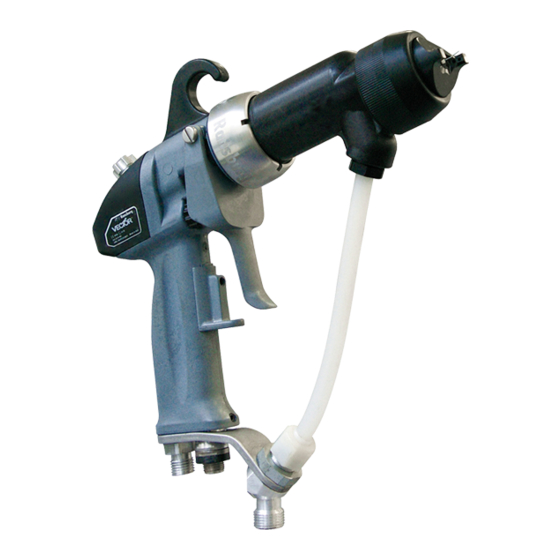
Page 59: R90 Classic Waterborne Electrostatic Spray Applicator Features
PARTS IDENTIFICATION Figure 31: R90 Classic Waterborne Electrostatic Spray Applicator Features R90 CLASSIC WATERBORNE ELECTROSTATIC SPRAY APPLICATOR FEATURES Description Description Needle/Electrode Adjustable Trigger Shelf Barrel Waterborne Hose Replaceable Hook High Voltage Cable Connection Fan Air Adjust Air Hose Connection 2-Finger/4-Finger Trigger Waterborne Source Connection AH-06-02-R16 (10/2019) 59 / 75... -
Page 60: Specifications - 79520 R90 Classic Waterborne
PARTS IDENTIFICATION SPECIFICATIONS 79520 R90 CLASSIC WATERBORNE Environmental/Physical Gun Length: 27cm (10.7 inches) Weight: 620 grams (21.9 oz.) Hose & Cable Lengths (Std): 10m, 15m, 20m, 25m, and 30m Atomizer Nozzle Assembly (Std): 79374-65, 79377-45 Electrical Operating Voltage: 90 kV DC (-) maximum Current Output: 140 microamperes maximum Part Sprayability: Determine sprayability of part to be coated using 76652, Test Equipment... -
Page 61: Control Unit
PARTS IDENTIFICATION CONTROL UNIT INPUTS / OUTPUTS 9060 Part # Voltage Designation Maximum Output 80130-511 220/240 VAC -65 kV DC 80130-512 110/120 VAC -90 kV DC 80130-513 220/240 VAC -90 kV DC CONTROL UNIT / APPLICATOR COMBINATIONS For Use With 9060 Part # 80130-51X 79520-XXXXX... -
Page 62: R90 Classic Waterborne Typical Installation
PARTS IDENTIFICATION R<1 MEGOHM Figure 32: R90 Classic Waterborne Typical Installation R90 CLASSIC WATERBORNE TYPICAL INSTALLATION Description Description Fluid Regulator AC Line Cord (110/220) Air Line 9060 Power Supply High Voltage Cable Vector Applicator Ball Valve Fluid Valve Isolated Fluid System Air Regulator W/Pressure Gauge (Protection required from human contact.) Air/Water Separator Main Air Supply Line... -
Page 63: Waterborne Isolation System Installation Guidelines
PARTS IDENTIFICATION • Fluid lines to the applicator MUST be protected from WA R N I N G scraping and abrasion on the floor or sharp metal edges that could lead to voltage pin holing and loss of kV on † Typical installations to spray non-flammable conduc- the charged system. tive materials (waterborne materials) must not be used to handle flamable materials (solvent based materials). • Cleanliness and maintenance are extremely critical. •... -
Page 64: Waterborne Fluid Delivery Components
PARTS IDENTIFICATION XX Refer to parts list for figure 33 Refer to parts list for figure 28 Figure 33: Waterborne Fluid Delivery Components AH-06-02-R16 (10/2019) 64 / 75 www.carlisleft.com... - Page 65 PARTS IDENTIFICATION WATERBORNE FLUID DELIVERY COMPONENTS - PARTS LIST (Figure 49) Part # Description Item # Table F - "F" Fluid Hose, Assembly* 74179-XX Bulk Tube, Fluid, 1/4" ID 72307-XX Bulk Tube, Fluid, 3/16" ID 72310-00 Connector, Bulk Head 10553-05 Nut, Hex 79438-00 Bracket, Support, Offset (Std.)
-
Page 66: Vector R90 Classic Waterborne Model Identification
PARTS IDENTIFICATION VECTOR R90 CLASSIC WATERBORNE MODEL IDENTIFICATION 79520 - A 0 = Applicator Only 1 = Domestic Sales, Complete W/ Power Supply 110/120 2 = Export Sales, Complete W/ Power Supply 240V, -50/60Hz 0 = Standard Spray, 65kV Air Cap, 1.4mm Fluid Nozzle, #44 1 = Standard Spray, 65kV Air Cap, 1.8mm Fluid Nozzle, #45 2 = Trans-Tech., 122V Air Cap, 1.8mm Fluid Nozzle, #245 3 = Round Spray 0 = No Fluid Hose 1 = Waterborne Fluid Hose, 1/4" ID x 10m... -
Page 67: Vector Hose Options
PARTS IDENTIFICATION Figure 34: Air Hose VECTOR AIR HOSE OPTIONS - PARTS LIST (Figure 34) Item # Part # Description 78547-10 Air Hose Assembly, 10m (33') 78547-15 Air Hose Assembly, 15m (49') 78547-20 Air Hose Assembly, 20m (66') 78547-31 Air Hose Assembly, 30m (99') LSFI0027 Reusable Hose Fitting 6919-XX Bulk Hose, Air Figure 35: Fluid Hose VECTOR FLUID HOSE OPTIONS - PARTS LIST (Figure 35) Item #... -
Page 68: Vector Applicator Cover Options
PARTS IDENTIFICATION Figure 36: Applicator Cover VECTOR APPLICATOR COVER OPTIONS - PARTS LIST Item # Part # Description 79529-00 Applicator Cover 79529-00-K5 Applicator Cover, Package of 5 Figure 37 - Swirl Nozzle VECTOR SWIRL NOZZLE OPTIONS - PARTS LIST Part # Description Item # 79959-00... -
Page 69: Vector Fluid Tube Options
PARTS IDENTIFICATION Figure 38: Fluid Tube VECTOR FLUID TUBE OPTIONS - PARTS LIST Qty. Part # Description See "Item 36" 9704-16 .093" ID Tube (Standard W/Applicator) .125" ID Tube See "Item 36" 9704-15 .250" ID Tube See "Item 36" 9704-11 NOTE †... -
Page 70: Parts Comparison
PARTS IDENTIFICATION PARTS COMPARISON 79374-65 Standard Air Spray Air Cap 79374-122 Trans-Tech Air Spray Air Cap Standard Air Spray Nozzles have a number between 44 and 148; Trans- Tech Air Spray Nozzles have a number between 244 and 348. Standard Air Spray Nozzles have a longer, narrower tip; Trans-Tech Air Spray Nozzles have a shorter, wider tip, and have a shorter over-all length. - Page 71 PARTS IDENTIFICATION 79555 TRANS-TECH. CONVERSION KITS AVAILABLE Description Kit Part No. Fluid Nozzle Part No. 79552-244 1.4mm (.055") Acetal 79555-244 79552-245 1.8mm (.070") Acetal 79555-245 79552-247 0.7mm (.028") Acetal 79555-247 79552-344 1.4mm (.055") Peek 79555-344 79552-345 1.8mm (.070") Peek 79555-345 79552-347 0.7mm (.028") Peek 79555-347...
-
Page 72: Vector Classic Recommended Spare Parts
PARTS IDENTIFICATION VECTOR CLASSIC APPLICATORS RECOMMENDED SPARE PARTS Part # Description 10051-05 Cup Seal, Spring Loaded 14061-05 Sponge, Conductive, Needle 14061-08 Sponge, Conductive, Handle 17130-00 Spring, Return 18842-01 PackingTube R90 18842-02 Packing Tube R70 19749-00 Applicator Wrench Accessory 3587-02 Nut and Ferrule 3587-03 Nut and Ferrule 59972-00... - Page 73 PARTS IDENTIFICATION VECTOR CLASSIC APPLICATORS RECOMMENDED SPARE PARTS (Cont.) Part # Description 79378-00 Gasket, Barrel 79379-00 Air Cap Retaining Ring 79385-00 Nut Connector Hose 79445-10 Fan Air Adjustment Assembly 79450-00 Trigger Stop Assembly 79454-00 Trigger Retaining Screws 79465-65 Barrel, R70 Classic 79465-85 Barrel, R90 Classic 79471-11 Rear Cover W/No Switch...
-
Page 74: Manual Change Summary
MANUAL CHANGES MANUAL CHANGE SUMMARY AH-06-02-R16 - Replaces AH-06-02-R15 with the following changes: Change Description Page(s) Change labels from 0518 to 2813 Update labels on images 12, 14, 16 AH-06-02-R16 (10/2019) 74 / 75 www.carlisleft.com... - Page 75 This product is covered by Carlisle Fluid Technologies materials and workmanship limited warranty. The use of any parts or accessories, from a source other than Carlisle Fluid Technologies, will void all warranties. For specific warranty information please contact Carlisle Fluid Technologies.
Need help?
Do you have a question about the Vector R Series and is the answer not in the manual?
Questions and answers