
Related Manuals for Carlisle MS Elite 805700


Summary of Contents for Carlisle MS Elite 805700
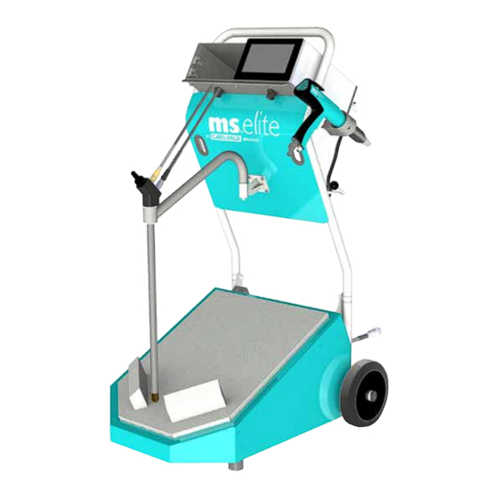
- Page 1 SERVICE MANUAL MS Elite Cart Powder Spray System Model: 805700 2813 PA-18-03-R6 (02/2022) 1 / 35 www.carlisleft.com...
- Page 2 MANUAL CHANGES NOTE: This manual has been changed from revision PA-18-03-R5 to revision PA-18-03-R6. Reasons for this change are noted under “Manual Change Summary” inside the back cover of this manual. PA-18-03-R6 (02/2022) 2 / 35 www.carlisleft.com...
-
Page 3: Table Of Contents
CONTENTS CONTENTS SAFETY: Safety Precautions ..............................4 Hazards / Safeguards ..............................5 ATEX/FM/UKEX: European ATEX Directive ............................9 APPROVALS (FM/ATEX): 10-13 80570 Model Identification ............................10 Specifications - elite Cart ............................13 INTRODUCTION: 14-17 Product Description ..............................14 Parts Breakdown .............................. -
Page 4: Safety
This information relates to USER SAFETY and PREVENTING and safety literature for your equipment, contact your local EQUIPMENT PROBLEMS. To help you recognize this Carlisle Fluid Technologies representative or Carlisle Fluid information, we use the following symbols. Please pay Technologies technical support. -
Page 5: Hazards / Safeguards
SAFETY Return To Contents AREA SAFEGUARDS HAZARD Tells where hazards Tells how to avoid the hazard. Tells what the hazard is. may occur. Fire Hazard Spray Area Fire extinguishing equipment must be present in the Improper or inadequate spray area and tested periodically. operation and maintenance procedures will cause a fire Spray areas must be kept clean to prevent the... - Page 6 SAFETY Return To Contents AREA SAFEGUARDS HAZARD Tells where hazards Tells how to avoid the hazard. Tells what the hazard is. may occur. Explosion Hazard Spray Area Improper or inadequate Electrostatic arcing must be prevented. Safe sparking operation and maintenance distance must be maintained between the parts being procedures will cause a coated and the applicator.
- Page 7 SAFETY Return To Contents AREA SAFEGUARDS HAZARD Tells where hazards Tells how to avoid the hazard. Tells what the hazard is. may occur. Spray Area / Electrical Discharge High Voltage There is a high voltage device Parts being sprayed and operators in the spray Equipment that can induce an electrical area must be properly grounded.
- Page 8 SAFETY Return To Contents AREA SAFEGUARDS HAZARD Tells where hazards Tells how to avoid the hazard. Tells what the hazard is. may occur. Electrical Electrical Discharge Unless specifically approved for use in hazardous Equipment locations, the power supply, control cabinet, and all High voltage equipment is utilized in the process.
-
Page 9: Atex/Fm/Ukex
ATEX/FM/UKEX ATEX/FM/UKEX EUROPEAN ATEX DIRECTIVE 2014/34/EU, ANNEX II, UKSI 2016: 1107 (AS AMENDED) The following instructions apply to equipment covered The certification of this equipment relies upon the by certificate number FM 19ATEX0004X, and following materials used in its construction: FM21UKEX0140X If the equipment is likely to come into contact with The equipment may be used with ignitable powders with... -
Page 10: Approvals (Fm/Atex)
APPROVALS (FM) Return To Contents APPROVALS (FM/ATEX) 805700 - AAAA B C - ZZ Y W Controller Type Language Pack Plug Assembly Applicator 2 Powder Hose/Cable Assembly Applicator 1 Powder Hose/Cable Assembly Cart Assembly Configuration Base Model Number Configuration DWG. 805700 PA-18-03-R6 (02/2022) 10 / 35 www.carlisleft.com... - Page 11 APPROVALS (FM) Return To Contents ELITE CART - TABLE OF “AAAA” DASHES “AAAA” Dash # “AAAA” Description 1VB1 Single Controller/ Applicator, Vibratory Box Fed, 115V elite Cart 1VB2 Single Controller/ Applicator, Vibratory Box Fed, 230V elite Cart 2VB1 Dual Controller/ Applicator, Vibratory Box Fed, 115V elite Cart 2VB2 Dual Controller/ Applicator, Vibratory Box Fed, 230V elite Cart 1FH1...
- Page 12 APPROVALS (FM) Return To Contents “W” Controller “ZZ” Plug TABLE OF “D” DASHES - CONTROLLER / PLUG PACKAGE “ZZ” Dash # “ZZ” Description Part No. None EU Plug Assembly 460147 North America/ Japan Plug Assembly 460149 China Plug Assembly 460150 Switzerland Plug Assembly 460148 UK Plug Assembly...
-
Page 13: Specifications - Elite Cart
APPROVALS (FM) Return To Contents SPECIFICATIONS - ELITE CART Controller Dimension Depth: 332.0mm (13.07 inches) Width: 200.6mm (7.89 inches) Height: 128.6mm (5.06 inches) Weight: 6.4 Kg (14.2 lbs) Applicator Dimensions Weight: 458g (Without cable and hose assembly) (15 oz.) Length: 350mm (Flat spray nozzle) (13.7 inches) Elite Cart Dimensions Depth:... -
Page 14: Introduction
INTRODUCTION Return To Contents INTRODUCTION PRODUCT DESCRIPTION Included with the vibratory box fed version is a quick method of cleaning powder in the supply line to the applicator. The MS elite is a small stand-alone coating unit. The unit Optionally, the cart can be equipped with a second controller, consists of a MS elite M5 manual powder spray gun, a a second manual powder spray gun, which are supplied by controller and an elite suction system or fluidized hopper... -
Page 15: Parts Breakdown
INTRODUCTION Return To Contents PARTS BREAKDOWN Item # Part # Description 461959-XXXMX MS elite Controller 615210 MS elite M5 Manual Applicator 835015-01 Single Controller/ Applicator, Vibratory Box Fed, 230V elite Cart (shown) 835015-02 Single Controller/ Applicator, Vibratory Box Fed, 115V elite Cart 835019-01 Dual Controller/ Applicator, Vibratory Box Fed, 230V elite Cart 835019-02... -
Page 16: Description - T9 Injector
INTRODUCTION Return To Contents DESCRIPTION Technical Data T9 Injector The T9 injector conveys powder to the applicator through the powder hose. It uses the fully adjustable feed and dosage air supplied from the MS elite controller to acheive a continuous adjustable powder feed rate. -
Page 17: Description - Elite Injector
INTRODUCTION DESCRIPTION Technical Data Elite Injector The elite Injector fluidizes and conveys powder to the appli- cator through the powder hose. It uses the fully adjustable feed and dosage air supplied from the MS elite controller to acheive a continuous adjustable powder feed rate. WA R N I N G †... -
Page 18: Installation
INSTALLATION Return To Contents INSTALLATION COMMISSIONING AND WA R N I N G OPERATION OF ELITE † The main power connection of MS powder CART SYSTEM coating device must be electrically interlocked with the exhaust system of the powder coating booth. The powder coating device must be switched on WA R N I N G only when the booth exhaust air is circulating. -
Page 19: Cart Manual Unpacking Instructions
INSTALLATION Return To Contents CART MANUAL UNPACKING 6. Reconnect barb fitting with powder hose attached to INSTRUCTIONS applicator. 1. Unpack and remove assembly from protective foam. 2. Remove applicator from individual box. 3. Remove barb fitting from applicator by pressing the clip and pulling down on the fitting. - Page 20 INSTALLATION Return To Contents 8. All applicator connections are now made. Place the 11. Plug in the power cord to the Line Power connector applicator in the provided holster. on the back of the controller. Take note of alignment pin. Tighten clockwise. Plug in the other end of the power cable to wall socket power supply outside all the classified zones.
- Page 21 INSTALLATION Return To Contents 13. Adjust the gun air regulator to open to check flow. 17. Place powder box on vibration table and insert suction pipe into box. (Steps 14-17 for vibratory box fed carts only. For fludizied 18. Turn on main air supply and set gun air regulator as hopper carts proceed to step 18.
-
Page 22: Operation
OPERATION Return To Contents OPERATION COLOR CHANGE CLEANING PROCESS (VIBRATORY BOX FED CARTS ONLY) 1. Lift the elite Injector out of the holder. 3. Follow the cleaning cycle instructions from the controller manual. Point the applicator into the booth. The trigger should not be actuated. -
Page 23: Maintenance
MAINTENANCE Return To Contents MAINTENANCE TROUBLESHOOTING GUIDE General Problem Possible Cause Solution Inconsistent See “Installing the Nozzle” section in PA-17-08. Wear bar or flat spray nozzle are improperly Powder Cloud oriented No Power or Check plug connections. Improper power cord connection. Air Delivery Check cable connections. -
Page 24: Parts Identification
PARTS IDENTIFICATION Return To Contents PARTS IDENTIFICATION VIBRATORY BOX FED ELITE CART (Continued On Next Page) PA-18-03-R6 (02/2022) 24 / 35 www.carlisleft.com... - Page 25 PARTS IDENTIFICATION VIBRATORY BOX FED ELITE CART - PARTS LIST Item # Part # Description 835015-XX MS Elite Single Cart Only (Shown) 835019-XX MS Elite Dual Cart Only 620240 Vibration Motor 230V 620245 Vibration Motor 115V 461959-XXXMX Topcase Controller 1*/2* 615210 MS Elite M5 Applicator 1*/2*...
-
Page 26: Ms Elite Injector (610015) - Parts List
PARTS IDENTIFICATION Return To Contents MS elite Injector (610015) MS ELITE INJECTOR (610015) - PARTS LIST Item # Part # Description Wear Part Main Body Intake System elite 620257 Dosing Nozzle with O-Ring 417223 O-Ring (Included in 620257) 417233-K5 O-Ring Service Kit (5 pack) 426638 Powder Plug 426639... -
Page 27: Suction Pipe Components - Parts List
PARTS IDENTIFICATION Return To Contents SUCTION PIPE COMPONENTS - PARTS LIST Item # Part # Description Wear Part 615127 Inner Injector Pipe with O-Ring 427061 O Ring 11x1 Viton 427061-K5 O Ring 11x1 Viton Kit (Kit of 5) 615128 Outer Tube with O-Ring 615126 Suction Intake with O-Ring 417186... -
Page 28: Elite Cart Vibratory Box Fed - Parts List
PARTS IDENTIFICATION Return To Contents VIBRATORY BOX FED ELITE CART (Continued On Next Page) PA-18-03-R6 (02/2022) 28 / 35 www.carlisleft.com... - Page 29 PARTS IDENTIFICATION VIBRATORY BOX FED ELITE CART - PARTS LIST Item # Part # Description 615501 MS Elite Single Cart Only (Shown) 615551 MS Elite Dual Cart Only 805501 Single Pump Fluidized Hopper 805551 Dual Pump Fluidized Hopper 461959-XXXMX Topcase Controller 1*/2* 615210 MS Elite M5 Applicator...
-
Page 30: Ms T9 Injector (810263) - Parts List
PARTS IDENTIFICATION Return To Contents MS T9 Injector (810263) MS T9 INJECTOR (810263) - PARTS LIST Item # Part # Description Wear Part T9 Injector Body 445450 T9 Injector Collecting Nozzle 445450-K5 T9 Injector Collecting Nozzle, Kit of 10 445470 T9 Injector Locknut 448060 M10 x 8 Pin... -
Page 31: Fluidized Box (805501/805551) - Parts List
PARTS IDENTIFICATION FLUIDIZED BOX (805501/805551) - PARTS LIST Item # Part # Description Wear Part 805501 30L Fludizied Box Assembly (1 Injector) 805551 30L Fluidized Box Assmebly (2 Injectors) (Shown) 610053 Powder Box Lid w/ 1 Injector 610054 Powder Box Lid w/ 2 Injectors (Shown) 810288 30L Fluid Box Assembly 810263... -
Page 32: Powder Hose Set (610139-Xx) - Parts List
PARTS IDENTIFICATION POWDER HOSE SET (610139-XX) - PARTS LIST Item # Part # Description Wear Part 810195-XX Powder Hose 10mm ID 810190-XX Powder Hose 11mm ID 461942-XX Hand Gun Cable, M5 421370-XX Gun Air Hose 620120 Velcro Band (Cut length 100mm x 30mm)* * Velcro band should not be placed within 1m of gun connection. -
Page 33: Air Hose (610144-Xx) - Parts List
PARTS IDENTIFICATION AIR HOSE (610144) - PARTS LIST Item # Part # Description Wear Part 615235 Antikink Hose Assembly 615236 Antikink Hose Assembly When ordered as a complete assembly 610144, the hoses will be shrink wrapped together. Single applicator carts require one 610144, while dual applicator cart require two 610144. -
Page 34: Manual Change Summary
MANUAL CHANGES Return To Contents MANUAL CHANGE SUMMARY PA-18-03-R6 - Replaces PA-18-03-R5 with the folowing changes: Change Description Page(s) New cover image and model number Update SAFETY section Insert new page from PA-19-06-R3 page 11 Update image and text Add table AAAADashes Udate text, left image, and table Update SPECIFICATION Update images and first paragraph... - Page 35 WARRANTY POLICY This product is covered by Carlisle Fluid Technologies’ materials and workmanship limited warranty. The use of any parts or accessories, from a source other than Carlisle Fluid Technologies, will void all warranties. Failure to reasonably follow any maintenance guidance provided, may invalidate any warranty.
Need help?
Do you have a question about the MS Elite 805700 and is the answer not in the manual?
Questions and answers