Table of Contents
Advertisement
Quick Links
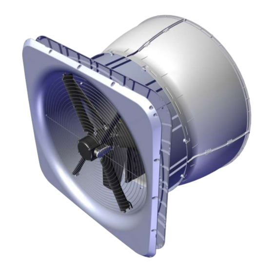
DA 1700 Wall Fan
Technical User Guide
English: For other language variants of this document we refer to:
Español: Para otras variantes del idioma de este documento, visite:
Français: Pour les versions dans d'autres langues de ce document veuillez consulter:
http://docs.skov.com/1195
2023.01.12 • 604252
Advertisement
Table of Contents

Related Manuals for Skov DA 1700


Summary of Contents for Skov DA 1700
- Page 1 DA 1700 Wall Fan Technical User Guide English: For other language variants of this document we refer to: Español: Para otras variantes del idioma de este documento, visite: Français: Pour les versions dans d'autres langues de ce document veuillez consulter: http://docs.skov.com/1195...
- Page 2 Product and Documentation Changes SKOV A/S reserves the right to change this manual and the product described herein without further notice. In case of doubt, please contact SKOV A/S. The date of change appears on the front and back pages.
-
Page 3: Table Of Contents
Placement in the livestock house .................15 General drawings ....................15 Preparing hole in wall .....................16 4.3.1 Necessary space for DA 1700 without LPC motor controller ......... 16 4.3.2 Necessary space for DA 1700 with LPC motor controller ..........16 4.3.3 Round hole in sandwich wall ................... 17 4.3.4... - Page 4 Mount the cone on the ventilation duct ................42 4.3.32 Mounting of inside safety net ................... 43 Mounting of accessories ..................44 4.4.1 DA 1700 magnet and tool kit .................... 44 4.4.2 Mounting of outside safety net ..................49 4.4.3 Mounting storm protection on outside safety net ............50 4.4.4...
- Page 5 Cable plan DA 1700 LPC 1x230 V ..................68 5.7.7 Circuit diagram DA 1700 LPC 1x230 V ................69 5.7.8 Circuit diagram DA 1700 LPC 1x230 V with thermal cutout ........... 70 5.7.9 Cable plan DA 1700 LPC 3x400 V ..................71 5.7.10 Circuit diagram DA 1700 LPC 3x400 V ................
- Page 6 DA 1700 plastic parts....................106 8.13 DA 1700 shutter motor ..................106 8.14 Dimensioned sketch .....................107 8.14.1 DA 1700 LPC with motor controller ................107 8.14.2 DA 1700 without motor controller .................. 107 8.14.3 Motor controller LPC 1x230 V ..................108 8.14.4 Motor controller LPC 3x400 V ..................
-
Page 7: Product Description
Technical User Guide 1 Product description The DA 1700 wall fan is a flange-mounted corrosion-free fan with cone and motor-controlled shutter. The fan is supplied in one version focused on low energy consumption and one version focused on maximizing air output. -
Page 8: Product Survey
Technical User Guide 2 Product survey DA 1700 Wall Fan... - Page 9 Technical User Guide At every order up to 100 pcs. DA 1700 wall fans, 1 pc. DA 1700 lifting kit and extra mounting parts are supplied. At every order from 101-200 pcs., DA 1700 wall fans, 2 pcs. DA 1700 lifting kit and extra mounting parts are supplied.
- Page 10 Controller. PM motor 230 V 2.3 kW 650 rpm. 4 m shielded motor cable four-core. Supplied with mounting parts for the assembly of the DA 1700. ErP 2015 approved. *Wall cover It should not be used at negative pressure higher than 100 Pa.
- Page 11 One per wall fan. 435375 DA 1700 outside suspension Use as needed if the DA 1700 is no longer in a horizontal position and does not retain its roundness. No screws supplied for fastening. One per wall fan.
- Page 12 435319 screw kit can be used for mounting of wall cover outside. 435319 DA 1700 screw kit DA 1700 screw kit can be used for mounting of DA 1700 in the wall. 1 per wall fan + 1 per wall cover Includes: 21 x tapping screw 4.8x70 pan TX25 A2 ISO14585C...
- Page 13 1 x potential free output relay 1 A, 30 V DC/24 V AC. 435990 DA 1700 cUL Protection Box Used in cases where a cUL approved DA 1700 is required (USA and Canada). Cable plan and circuit diagram can be found in the supplied documentation.
-
Page 14: General Information
Technical User Guide 3 General information Recommended tools Below follows a list of tools recommended for installation of your DA 1700 wall fan. Part Description Cordless drill Jigsaw Socket wrench set, incl. 10 and 17 mm top Combination spanner kit, incl. 10 mm and 17 mm... -
Page 15: Mounting Guide
DA 1700 wall fans are placed in the livestock house according to the drawing supplied. Contact SKOV A/S in case of significant deviation. It is checked that all DA 1700 wall fans can be placed freely in relation to the other equipment, upon agreement with the owner. -
Page 16: Preparing Hole In Wall
Technical User Guide Preparing hole in wall 4.3.1 Necessary space for DA 1700 without LPC motor controller There must be a minimum of 50 mm of space inside the livestock house for the DA 1700 wall fan. There must be minimum... -
Page 17: Round Hole In Sandwich Wall
The minimum distance with use of LPC controller is 550 mm. Without an LPC controller, the distance can be reduced to a minimum of 275 mm. Figure 4: Minimum distance between DA 1700 Figure 5: Minimum distance from DA 1700 to wall, floor and ceiling DA 1700 Wall Fan... -
Page 18: Square Hole In Concrete And Brick Wall
The minimum distance with use of LPC controller is 550 mm. Without an LPC controller, the distance can be reduced to a minimum of 275 mm. Figure 6: Minimum distance between DA 1700 Figure 7: Minimum distance from DA 1700 to wall, floor and ceiling DA 1700 Wall Fan... -
Page 19: Square Hole In Wooden Wall
The minimum distance with use of LPC controller is 550 mm. Without an LPC controller, the distance can be reduced to a minimum of 275 mm. Figure 8: Minimum distance between DA 1700 Figure 9: Minimum distance from DA 1700 to wall, floor and ceiling DA 1700 Wall Fan... -
Page 20: Measure And Saw Out The Holes
Technical User Guide 4.3.6 Measure and saw out the holes Remember to always use a spirit level. The holes should be roughly 10 mm right through the wall. Cut the holes. DA 1700 Wall Fan... -
Page 21: Press The Front Panel Together
Technical User Guide 4.3.7 Press the front panel together Lay the four front panels on the floor. Press the front panels together in all four corners. DA 1700 Wall Fan... -
Page 22: Click And Seal The Ventilation Ducts Together
Technical User Guide 4.3.8 Click and seal the ventilation ducts together Point the side of the ventilation duct. Click the four ventilation ducts together alternately. entilation ducts without motor suspension (1). entilation ducts with motor suspension (2). DA 1700 Wall Fan... -
Page 23: Position The Ventilation Duct On The Front Panel
4.3.10 Mount the ventilation duct on the front panel Assemble the front panel and the ventilation duct using: • 16 M6x25 screws • 32 Ø6 washers • 16 bushings ø6/ø10 x 11.6 • 16 M6 self-locking nuts DA 1700 Wall Fan... - Page 24 Technical User Guide Then assemble the front panel and the ventilation Duct using: • 12 M6x25 screws • 24 Ø6 washers • 12 bushings ø6/ø10 x 11.6 • 12 M6 self-locking nuts DA 1700 Wall Fan...
-
Page 25: Mount The Fork Piece On The Shutter
Outside Outside Inside Mount the fork piece on the two shutters using: • 2 M6x25 screws • Inside 2 Ø6.4/ø18x1.2 washers • 4 Ø6.4/ø40x1.5 washers • 4 bushings ø6.4/ø10x5.7 • 2 M6 self-locking nuts DA 1700 Wall Fan... -
Page 26: Mount The Shutter On The Center Pillar
Mount top and bottom brackets on the center pillar using: • 2 M6x50 screws • 4 Ø6,4/ø18x1,2 washers • 2 bushings ø6/ø10x39,6 • 2 M6 self-locking nuts Make sure that the two holes in the center pillar are at the bottom. Bund DA 1700 Wall Fan... -
Page 27: Mount The Shutter Lock Onto The Center Pillar
Technical User Guide 4.3.13 Mount the shutter lock onto the center pillar Mount the shutter lock through the shutter and down around the center pillar. Make sure that the shutter lock snaps into the center pillar. DA 1700 Wall Fan... -
Page 28: Mount The Axle In The Shutter Motor
Mount the axle without teeth (2) in the shutter motor. Mount the axle on the shutter motor using: • 1 M6x80 screw • 2 Ø6 washers • 1 bushing ø6/ø10 x 69.6 • 1 M6 self-locking nut DA 1700 Wall Fan... -
Page 29: Mount Fork Piece And Connection Piece On The Shutter Motor (Lpc)
• 4 Ø6 washers • 2 bushings ø6/ø10 x 11.6 • 2 M6 self-locking nuts Connection piece is used for DA 1700 with LPC motor controller. Mount the two connection pieces on the shutter motor using: • 2 M6x25 screws •... -
Page 30: Mount Fork Piece And Spring On The Shutter Motor (On/Off)
2 M6x25 screws • 4 Ø6 washers • 2 bushings ø6/ø10 x 11.6 • 2 M6 self-locking nuts Spring is used for DA 1700(ON/OFF) Mount the two springs on the shutter motor using: • 2 M6x25 screws • 4 Ø6 washers •... -
Page 31: Mount The Shutter Motor On The Center Pillar
• 2 M6x80 screws • 4 Ø6 washers • 2 bushings ø6/ø10 x 11.6 • 2 M6 self-locking nuts Mount the cable clamp on the cable and click it into the center pillar. Bottom DA 1700 Wall Fan... -
Page 32: Connect The Fork Piece And The Connection Piece Together (Lpc)
• 2 M6x25 screws • 4 Ø6 washers • 2 bushings ø6/ø10 x 11.6 • 2 M6 self-locking nuts Press on the manual trigger to turn the arms on the shutter motor, see section 4.3.17. DA 1700 Wall Fan... -
Page 33: Mount The Center Pillar On The Ventilation Duct
Make sure the arrow on the shutter motor is pointing upwards. Bottom Mount the center pillar on the ventilation duct using: • 2 M6x25 screws • 4 Ø6 washers • 2 bushings ø6/ø10x11,6 • 2 M6 self-locking nuts DA 1700 Wall Fan... -
Page 34: Mount Da 1700 In Wall
Make sure the arrow on the shutter motor is pointing upwards. Centre DA 1700 in the hole, use wedges at the bottom. Use the holes in DA 1700 to mark out holes in the wall. Mounting on a sandwich wall: Drill 3 mm holes in the wall. -
Page 35: Mount Fan Blades On The Motor Shaft
Technical User Guide 4.3.22 Mount fan blades on the motor shaft For the assembly of fan blades see Instruction included in DA 1700 fan blade kit. The 3 fan blades delivered together, must NOT be mixed with other fan blades. -
Page 36: Mount Lifting Kit
4.3.25 Mount motor to bottom motor suspensions in the fan housing Mount motor with the two bottom motor suspensions in the fan housing using: • 2 M6x80 screws • 4 Ø6 washers • 2 bushings ø6/ø10 x 69.6 • 2 M6 self-locking nuts DA 1700 Wall Fan... -
Page 37: Mount Top Motor Suspensions To The Motor And The Fan Housing
• 8 mm hole for the winch motor cable at the top. • 13 mm hole for the fan motor cable at the bottom. DA 1700 Wall Fan... - Page 38 • 3 cable ties 188 x 4.8 mm, black Before mounting the cone, pull the cables around the ventilation duct and in through the drilled holes. For sealing when leading through cables, see section 4.3.29. DA 1700 Wall Fan...
-
Page 39: Foam And Seal The Outer Side
For foaming: Single-component polyurethane foam or similar. You must check how much the foam expands before you start foaming. • For pointing: Sikaflex 111 Stick & Seal. Foam around the ventilation duct. Foam in four places around the ventilation duct. DA 1700 Wall Fan... - Page 40 Technical User Guide With use of outside cover, apply a sealing edge at the transition between wall and duct. DA 1700 Wall Fan...
-
Page 41: Seal The Inner Side
Technical User Guide 4.3.29 Seal the inner side SKOV A/S recommends using Sikaflex 111 Stick & Seal for the pointing task. Apply a sealing edge between the wall fan and the wall. Apply a seal next to the place where the cables have been led through. -
Page 42: Assembly Of Cone
Click the sides together. 4.3.31 Mount the cone on the ventilation duct Mount the assembled cone onto the ventilation duct using: • 8 M6x25 screws • 16 Ø6 washers • 8 bushings ø6/ø10x11.6 • 8 M6 self-locking nuts DA 1700 Wall Fan... -
Page 43: Mounting Of Inside Safety Net
Secure the inside safety net in the four motor suspension brackets using: • 12 4x30 screws • 12 Ø4.3 washers Ensure the screws are screwed in tightly. DA 1700 Wall Fan... -
Page 44: Mounting Of Accessories
Technical User Guide Mounting of accessories 4.4.1 DA 1700 magnet and tool kit The overview picture shows the placement of the magnets and washers when the assembly is complete. 1. Nut holder outside duct and magnet holder inside duct. 2. Machine screw and washer - welded inside shutter and nut M4 flange lock nut outside shutter. - Page 45 Use the drilling template for the hole in the shutter. Place the template against the shutter. Make a line on the duct/cone with a marker. Drill a 4.5 mm hole through the template into the shutter. DA 1700 Wall Fan...
- Page 46 Use the drilling template again for the holes in the duct. Turn the template and place it against duct on top of the marked line. Drill the three holes with the 4.5 mm drill. DA 1700 Wall Fan...
- Page 47 Technical User Guide Picture of where to push in the nut holder. Place the nut holder between the duct and the cone. Make sure that the pin slides into the middle hole. DA 1700 Wall Fan...
- Page 48 The nut can fall out of the nut holder, if the screw is pressed too hard. Mount washer for magnet on the shutter. Mount machine screw and washer - welded inside shutter. Mount M4 flange lock nut outside shutter. DA 1700 Wall Fan...
-
Page 49: Mounting Of Outside Safety Net
4.4.2 Mounting of outside safety net If DA 1700 outside safety guard is deselected - a safety distance to prevent hazard zones must be established. The demands in the International Standard for Safety of Machinery ISO 13857 must be followed. -
Page 50: Mounting Storm Protection On Outside Safety Net
Mounting storm protection on outside safety net Mount the storm protection on the outside safety net with: 2 stk. PT screw 6x20 TX30 Make sure the shutters can open and close when the Storm Protection is mounted. DA 1700 Wall Fan... -
Page 51: Mounting Storm Protection Wire For Cone
4.4.4 Mounting storm protection wire for cone Drill an Ø5 mm hole for the wire in the top and bottom Mount the washer, steel wire and wire lock. Is used if outside safety net is deselected. DA 1700 Wall Fan... -
Page 52: Mounting Of Outside Wall Cover
If necessary, use a saw to adjust the cover size. Then mount all four covers on the wall with the aid of screws (not supplied by SKOV A/S) For sealing, see section 4.3.28 DA 1700 Wall Fan... -
Page 53: Mounting Outside Suspension
Mount the snap hook in the chain and the suspension fitting. Mount the shackle in the turnbuckle and bracket on the wall. Mount the hook of the turnbuckle in the chain. DA 1700 Wall Fan... -
Page 54: Mounting Of Insulation Plate
Cut off the extra sealing profile. Mount the tape on the jointing. Mount the insulation cover at the end of the fan motor using: • 1 lock for insulation plate DA 1700 Wall Fan... -
Page 55: Installation Guide
1700 cUL Protection box when DA 1700 wall fan is installed with optional cUL components. Supplied connection box and power supply isolator for DA 1700 wall fan are not UL components and must not be used in installations intended for UL approval. -
Page 56: Cabling To Da 1700
Technical User Guide 5.1.3 Cabling to DA 1700 Example of cabling to electrical box and LPC. For cabling from shutter motor and fan, see section 4.3.27. 5.1.4 Cabling into the LPC motor controller In order to prevent water from running into the motor... -
Page 57: Connection In The Lpc Motor Controller
Terminal block for programming interface RJ12 programming connector (2 x slave / 1 x master) 3-point strain relief for Modbus cable Power supply terminals for 1-phase (L, N, PE) and 3-phase (L1, L2, L3, N, PE) DA 1700 Wall Fan... -
Page 58: Terminals For 230 V Power Supply
Terminals for power supply to fan Remember to strip the cable so that the protective shield from the fan can be connected to the motor controller during mounting under the rail. Power supply from motor controller to fan motor. DA 1700 Wall Fan... -
Page 59: Signal Terminals
5.2.5 Terminals on relay module (accessories) Relay module can be purchased as 445076 accessories. Alarm NO Max. 30 V DC/24 V AC, 1A Alarm NC For assembly of the alarm relay, see section 5.7.12 and 5.7.13 DA 1700 Wall Fan... -
Page 60: Led Indication On Lpc Motor Controller
• Flashes red in case of at least one non-critical alarm. Alarms DA 1700 LPC motor controller including relay module provides alarm monitoring which monitors the optimal and flawless operation and generates an alarm if operating or performance problems are observed. -
Page 61: Emergency Opening For Da 1700 Shutter Motor
Technical User Guide Emergency opening for DA 1700 shutter motor If emergency opening for the shutter motor is required, it must be powered from F6 24 V power supply in the climate controller. For wall fans that do not require emergency opening, the shutter motor is powered by an external 24 V power supply without battery backup. -
Page 62: Fans Not Active At Failure
Example of terminal number. For correct installation see the setup menu on controller Show connection External 24V is mounted on NC relay in the climate controller. 0V is mounted on NO relay in the climate controller. DA 1700 Wall Fan... -
Page 63: Connection To Shutter Motor
(ten times/second) H1 and H3 Power and H2 signal from climate controller. H9 O.C (transistor output) is used to DA 1700 with LPC controller. H10/11a and H12a Relay output is used to DA 1700 without controller. DA 1700 Wall Fan... - Page 64 Technical User Guide O.C ON/OFF H9 is placed on PCB for shutter motor. Used for start/stop of the DA 1700 with LPC controller. t takes 10 seconds from the start signal until the fan starts rotating. Relay ON/OFF H11 and H12 is placed on PCB for shutter motor.
-
Page 65: Cable Plans And Circuit Diagrams
All motors and LPCs must be mounted with a power supply isolator. 5.7.4 Letter codes Reference designations are in accordance with IEC/EN61346-2 Protective equipment Climate controller Fan motor Supply isolator Switch Cable RCCB Contactor Initial fuse Protective motor switch DA 1700 Wall Fan... -
Page 66: Circuit Diagrams For Off/Auto/On Switch
Technical User Guide 5.7.5 Circuit diagrams for OFF/AUTO/ON switch 5.7.5.1 Control voltage (LPC) Example of terminal number. For correct installation see the setup menu Show connection on controller Power supply from terminals in the climate controller DA 1700 Wall Fan... -
Page 67: Control Voltage (Without Lpc)
Technical User Guide 5.7.5.2 Control voltage (without LPC) Example of terminal number. For correct installation see the setup menu on controller Show connection Power supply from terminals in the climate controller DA 1700 Wall Fan... -
Page 68: Cable Plan Da 1700 Lpc 1X230 V
Technical User Guide 5.7.6 Cable plan DA 1700 LPC 1x230 V DA 1700 wall fan Climate controller Supply DA 1700 controller Connection box Supply isolator 4 m shielded cable 4 m cable Only used for LPC fan w/thermal cutout DA 1700 Wall Fan... -
Page 69: Circuit Diagram Da 1700 Lpc 1X230 V
Technical User Guide 5.7.7 Circuit diagram DA 1700 LPC 1x230 V Example of terminal number. For correct installation see the setup menu on controller Show connection Power supply from terminals in the climate controller DA 1700 Wall Fan... -
Page 70: Circuit Diagram Da 1700 Lpc 1X230 V With Thermal Cutout
Technical User Guide 5.7.8 Circuit diagram DA 1700 LPC 1x230 V with thermal cutout Example of terminal number. For correct installation see the setup menu on controller Show connection Power supply from terminals in the climate controller DA 1700 Wall Fan... -
Page 71: Cable Plan Da 1700 Lpc 3X400 V
Technical User Guide 5.7.9 Cable plan DA 1700 LPC 3x400 V DA 1700 wall fan Climate controller Supply DA 1700 controller Connection box Supply isolator 4 m shielded cable 4 m cable Only used for LPC fan w/thermal cutout DA 1700 Wall Fan... -
Page 72: Circuit Diagram Da 1700 Lpc 3X400 V
Technical User Guide 5.7.10 Circuit diagram DA 1700 LPC 3x400 V Example of terminal number. For correct installation see the setup menu Power supply from on controller Show connection terminals in the climate controller DA 1700 Wall Fan... -
Page 73: Circuit Diagram Da 1700 Lpc 3X400 V With Thermal Cutout
Technical User Guide 5.7.11 Circuit diagram DA 1700 LPC 3x400 V with thermal cutout Example of terminal number. For correct installation see the setup menu on controller Show connection Power supply from terminals in the climate controller DA 1700 Wall Fan... -
Page 74: Cable Plan Da 1700 Lpc 3X400 V With Alarm Relay
Technical User Guide 5.7.12 Cable plan DA 1700 LPC 3x400 V with alarm relay DA 1700 wall fan Climate controller Supply DA 1700 controller Connection box Supply isolator 4 m shielded cable 4 m cable DA 1700 Wall Fan... -
Page 75: Circuit Diagram Da 1700 Lpc 3X400 V With Alarm Relay
Technical User Guide 5.7.13 Circuit diagram DA 1700 LPC 3x400 V with alarm relay Example of terminal number. For correct installation see the setup menu on controller Show connection Power supply from terminals in the climate controller DA 1700 Wall Fan... -
Page 76: Cable Plan Da 1700 Lpc 3X230 V
Technical User Guide 5.7.14 Cable plan DA 1700 LPC 3x230 V DA 1700 wall fan Climate controller Supply DA 1700 controller Connection box Supply isolator 4 m shielded cable 4 m cable Only used for LPC fan w/thermal cutout DA 1700 Wall Fan... -
Page 77: Circuit Diagram Da 1700 Lpc 3X230 V
Technical User Guide 5.7.15 Circuit diagram DA 1700 LPC 3x230 V Example of terminal number. For correct installation see the setup menu Power supply from on controller Show connection terminals in the climate controller DA 1700 Wall Fan... -
Page 78: Circuit Diagram Da 1700 Lpc 3X230 V With Thermal Cutout
Technical User Guide 5.7.16 Circuit diagram DA 1700 LPC 3x230 V with thermal cutout Example of terminal number. For correct installation see the setup menu on controller Show connection Power supply from terminals in the climate controller DA 1700 Wall Fan... -
Page 79: Cable Plan Da 1700 3X400 V
Technical User Guide 5.7.17 Cable plan DA 1700 3x400 V Climate controller DA 1700 wall fan Wiring box Connection box Supply isolator 4 m cable 4 m cable Only used for fan w/thermal cutout DA 1700 Wall Fan... -
Page 80: Circuit Diagram Da 1700 3X400 V
Technical User Guide 5.7.18 Circuit diagram DA 1700 3x400 V Example of terminal number. For correct installation see the setup menu on controller Show connection Power supply from terminals in the climate controller DA 1700 Wall Fan... -
Page 81: Circuit Diagram Da 1700 3X400 V With Thermal Cutout
Technical User Guide 5.7.19 Circuit diagram DA 1700 3x400 V with thermal cutout Example of terminal number. For correct installation see the setup menu on controller Show connection Power supply from terminals in the climate controller DA 1700 Wall Fan... -
Page 82: Cable Plan Da 1700 3X230 V
Technical User Guide 5.7.20 Cable plan DA 1700 3x230 V Climate controller DA 1700 wall fan Wiring box Connection box Supply isolator 4 m cable 4 m cable Only used for fan w/thermal cutout DA 1700 Wall Fan... -
Page 83: Circuit Diagram Da 1700 3X230 V
Technical User Guide 5.7.21 Circuit diagram DA 1700 3x230 V Example of terminal number. For correct installation see the setup menu on controller Show connection Power supply from terminals in the climate controller DA 1700 Wall Fan... -
Page 84: Circuit Diagram Da 1700 3X230 V With Thermal Cutout
Technical User Guide 5.7.22 Circuit diagram DA 1700 3x230 V with thermal cutout Example of terminal number. For correct installation see the setup menu on controller Show connection Power supply from terminals in the climate controller DA 1700 Wall Fan... -
Page 85: Cable Plan Da 1700 Lpc 3X400 V Stand Alone
Technical User Guide 5.7.23 Cable plan DA 1700 LPC 3x400 V stand Alone DA 1700 Wall fan Wiring box DA 1700 controller Connection Supply isolator Shielded 4 m cable 4 m cable DA 1700 Wall Fan... -
Page 86: Circuit Diagram Da 1700 Lpc 3X400 V Stand Alone
Technical User Guide 5.7.24 Circuit diagram DA 1700 LPC 3x400 V stand alone DA 1700 Wall Fan... -
Page 87: Cable Plan Da 1700 3X400 V Stand Alone
Technical User Guide 5.7.25 Cable plan DA 1700 3x400 V stand alone DA 1700 Wall fan Wiring box Connection box Supply isolator 4 m cable 4 m cable DA 1700 Wall Fan... -
Page 88: Circuit Diagram Da 1700 3X400 V Stand Alone
Technical User Guide 5.7.26 Circuit diagram DA 1700 3x400 V stand alone DA 1700 Wall Fan... -
Page 89: Maintenance Instructions
Cleaning the fan Clean the fan at regular intervals so that cooling and air can pass through unimpeded. 1. Set the controller to the in-between function (when using a SKOV controller). Wash, 2. Rinse out the fan duct. Remember that fans cannot withstand high-pressure cleaning. -
Page 90: Troubleshooting Guide
Remedy the damage. Flap touches the ventilation duct Flashing (obstructed). quickly** DA 1700 shutter will not Linkage between flap and gear faulty. Replace defective parts. close/open See section 5.6 and circuit diagrams. ON/OFF signal from controller / manual operation is lacking. - Page 91 Start/stop signal (24V = stop terminal 8). Check signal from the winch motor. running Supply is lacking. Check supply. No light Defective LPC motor controller. Replace LPC motor controller. * For LED indications, see section 5.3 DA 1700 Wall Fan...
-
Page 92: Technical Data
Technical User Guide 8 Technical data DA 1700 LPC 1x230 V 435354 Fan type DA 1700-5 LPC 1x230 V Electrical 230 ± 10 % Rated voltage [V AC] 175 – 280 Operational voltage [V AC] If supply voltage is below the rated voltage, reduced fan RPM may occur depending on the load and surrounding temperature. - Page 93 Aluminium (EN AB-44300) Bottom Aluminium 5052 Polypropylene (PP) *Fan noise, outside (2 m, 45 degrees) [dB(A)] Shipping DA 1700 fan housing packed HxWxD [mm] 800x735x1.600 Inside safety net packed HxWxD [mm] 3x1410x1.354 Fan motor packed HxWxD [mm] 320x320x400 Fan blade packed HxWxD [mm]...
-
Page 94: Erp/Ecodesign Da 1700 Lpc 1X230 V
Specific ratio The product is designed for recycling and it will be possible for customers to Recycling/Disposal deliver worn-out product to SKOV A/S or to local collection sites/recycling stations according to local instructions. Impact on environmental Additional items used when determining DA 1700 wall fan incl. -
Page 95: 1700 Lpc 3X400 V
Technical User Guide DA 1700 LPC 3x400 V 435358/435359 Fan type DA 1700-6 LPC 3x400 V Electrical 3x400 ± 10 % Rated voltage [V AC] 280 – 485 Operational voltage [V AC] If supply voltage is below the rated voltage, reduced fan RPM may occur depending on the load and surrounding temperature. - Page 96 Aluminium (EN AB-44300) Bottom Aluminium 5052 Polypropylene (PP) *Fan noise, outside (2 m, 45 degrees) [dB(A)] Shipping DA 1700 fan housing packed HxWxD [mm] 800x735x1.600 Inside safety net packed HxWxD [mm] 3x1.410x1.354 Fan motor packed HxWxD [mm] 320x320x400 Fan blade packed HxWxD [mm]...
-
Page 97: Erp/Ecodesign Da 1700 Lpc 3X400 V
Specific ratio Recycling/Disposal The product is designed for recycling and it will be possible for customers to deliver worn-out product to SKOV A/S or to local collection sites/recycling stations according to local instructions. Impact on environmental Additional items used when determining the fan energy DA 1700 wall fan incl. -
Page 98: 1700 Lpc 3X230 V/3X200 V
Technical User Guide DA 1700 LPC 3x230 V/3x200 V 435373 Fan type DA 1700-6 LPC 3x230 V/3x200 V Electrical Rated voltage – 3x230 V [V AC] 3x230 ± 10 % Rated voltage – 3x200 V [V AC] 3x200 ± 10 % 170 –... - Page 99 Aluminium (EN AB-44300) Bottom Aluminium 5052 Polypropylene (PP) *Fan noise, outside (2 m, 45 degrees) [dB(A)] Shipping DA 1700 fan housing packed HxWxD [mm] 800x735x1600 Inside safety net packed HxWxD [mm] 3x1.410x1354 Fan motor packed HxWxD [mm] 320x320x400 Fan blade packed HxWxD [mm]...
-
Page 100: Erp/Ecodesign Da 1700 Lpc 3X230 V
Specific ratio Recycling/Disposal The product is designed for recycling and it will be possible for customers to deliver worn-out product to SKOV A/S or to local collection sites/recycling stations according to local instructions. Impact on environmental Additional items used when determining the fan energy DA 1700 wall fan incl. - Page 101 Ambient humidity, operation [%] RH 10-95 Protection class Fan motor: IP 65 *Fan noise, outside (2 m, 45 degrees) [dB(A)] Shipping DA 1700 fan housing packed HxWxD [mm] 800x735x1600 800x735x1600 Inside safety net packed HxWxD [mm] 3x1410x1354 3x1.410x1354 Fan motor packed HxWxD [mm]...
- Page 102 Specific ratio Recycling/Disposal The product is designed for recycling and it will be possible for customers to deliver worn-out product to SKOV A/S or to local collection sites/recycling stations according to local instructions. Impact on environmental Additional items used when determining the fan energy DA 1700 wall fan incl.
- Page 103 Ambient humidity, operation [%] RH 10-95 Protection class Fan motor: IP 65 *Fan noise, outside (2 m, 45 degrees) [dB(A)] Shipping DA 1700 fan housing packed HxWxD [mm] 800x735x1600 Inside safety net packed HxWxD [mm] 3x1.410x1354 Fan motor packed HxWxD [mm] 320x320x400...
-
Page 104: Erp/Ecodesign Da 1700 3X230 V
Specific ratio The product is designed for recycling and it will be possible for customers to deliver Recycling/Disposal worn-out product to SKOV A/S or to local collection sites/recycling stations according to local instructions. Impact on environmental Additional items used when determining the fan energy DA 1700 wall fan incl. -
Page 105: Light Traps
Start temperature [°C] ÷ 40 til +50 Storage temperature [°C] ÷ 40 til +70 Ambient humidity, operation [%] RH 10-95 Light reduction factor 17,000:1 Shipping Light trap packed HxWxD [mm] 310x270x1710 Light trap weight [g] 54,000 DA 1700 Wall Fan... -
Page 106: 1700 Plastic Parts
8.12 DA 1700 plastic parts DA 1700 plastic parts Mechanical Material Front panel Fan ducts Shutter PS (HIPS) Wall cover outside Cover centre pillar Cover motor suspension Diffuser Motor suspension PP (GF30) House for shutter Shutter parts Metal parts Stainless steel A2... -
Page 107: Dimensioned Sketch
Technical User Guide 8.14 Dimensioned sketch Measure in mm. 8.14.1 DA 1700 LPC with motor controller 8.14.2 DA 1700 without motor controller DA 1700 Wall Fan... -
Page 108: Motor Controller Lpc 1X230 V
Technical User Guide 8.14.3 Motor controller LPC 1x230 V 8.14.4 Motor controller LPC 3x400 V 8.14.5 Motor controller LPC 3x230 V DA 1700 Wall Fan... -
Page 109: Light Trap
Technical User Guide 8.14.6 Light trap DA 1700 Wall Fan... -
Page 110: Enclosures
Assembly Foaming Pointing Check that all joints are in accordance with Technical User Guide DA 1700 wall fan. Check that the setting of the motor protection is correct, see section 8 Technical data (Max. power consumption [A]). Check that there is a contactor in front of the fan without LPC motor controller. - Page 111 Check that the fan blades rotate clockwise (seen from inside the livestock house). Remarks Has the customer been introduced to operating DA 1700. Date of start-up: Customer signature:...
- Page 112 SKOV A/S • Hedelund 4 • Glyngøre • DK-7870 Roslev Tel. +45 72 17 55 55 • Fax +45 72 17 59 59 • www.skov.com • Email: skov@skov.dk...
Need help?
Do you have a question about the DA 1700 and is the answer not in the manual?
Questions and answers