Table of Contents
Advertisement
Technical User Guide
English For other language variants of this document we refer to:
Español Para otras variantes del idioma de este documento, visite:
Français Pour les versions dans d'autres langues de ce document veuillez consulter:
604484 • 2022-05-23
DA 820F-3 VFD
Fan High Pressure
http://docs.skov.com/1221
Advertisement
Table of Contents

Subscribe to Our Youtube Channel
Related Manuals for Skov DA 820F-3 VFD


Summary of Contents for Skov DA 820F-3 VFD
- Page 1 DA 820F-3 VFD Fan High Pressure Technical User Guide English For other language variants of this document we refer to: Español Para otras variantes del idioma de este documento, visite: Français Pour les versions dans d'autres langues de ce document veuillez consulter: http://docs.skov.com/1221...
- Page 3 Note • All rights belong to SKOV A/S. No part of this manual may be reproduced in any manner whatsoever without the expressed written permission of SKOV A/S in each case.
-
Page 4: Table Of Contents
Power supply isolator......................... 24 4.6.3 Letter Code .......................... 24 Cable plans and circuit diagrams................... 25 4.7.1 DA 820F-3 VFD 400 V with DA 74CO ON/OFF ................ 25 4.7.1.1 Cable plan.......................... 25 4.7.1.2 Terminals in VFD 400 V fan....................... 25 4.7.1.3 Terminals in DA 74CO ....................... - Page 5 Recycling/Disposal ........................ 33 6 Trouble shooting instructions ........................ 34 7 Technical data .............................. 36 DA 820F-3 VFD 3x400 V...................... 36 7.1.1 Erp/Ecodesign DA 820F-3 VFD 3x400 V .................. 38 Dimensioned sketch ........................ 39 7.2.1 DA 820F-3 VFD ........................ 39 Technical User Guide...
-
Page 6: Product Description
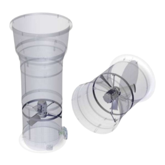
DA 820F-3 VFD 1 Product description The ON/OFF fan is controlled with a sturdy frequency converter for three-phase fans. The frequency converter is controlled by a 10-0 V signal from a cli- mate controller. The fans are designed for mounting in exhaust units and wall exhaustion in livestock houses where the ventila- tion system operates in the high pressure range. -
Page 7: Product Survey
2 Product survey 2.1 DA 820F-3 VFD high pressure 445140 DA 820F-3 VFD fan high pressure 400V3 50/60Hz This product consists of a 3x400 V fan and a frequency converter. The frequency converter is controlled via a 10-0 V signal. -
Page 8: Mounting Guide
DA 820F-3 VFD 3 Mounting guide 3.1 Recommended tools A list of the recommended tools for mounting purposes can be seen below. Item Description Cordless drill Screwdriver bits Drill kit Multimeter Utility knife Side cutter Pointed pliers Screwdriver Allen key kit... -
Page 9: Mounting The Ring With Fan Suspension In The Exhaust Unit
DA 820F-3 VFD 3.2 Mounting the ring with fan suspension in the exhaust unit Place the ring with fan suspension 200 mm from the top 200 mm edge. Mark up the 8 holes. Drill the 8 holes at the markings with an ø8 drill bit. -
Page 10: Mounting The Fan In The Exhaust Unit
DA 820F-3 VFD 3.3 Mounting the fan in the exhaust unit The fans must face the fan blades downward. Position the legs of the fan in the 4 fan suspension units. Attach the fan suspension at all 4 legs using: •... -
Page 11: Mounting The Fan In The Wall Exhaustion
DA 820F-3 VFD 3.4 Mounting the fan in the wall exhaustion When the fan is used as wall exhaustion, the terminal box on the fan must turn as shown in the picture and the drain screw must be removed. The fan must face the fan blades inwards. -
Page 12: Mounting Support Kit
DA 820F-3 VFD 3.4.1 Mounting support kit Mount bracket (A) on fan duct using: • 1 x M6x30 screw • 1 x M6 self-locking nut Replace the M8x20 screw in the fan suspension with M6x30. Mount threaded rod (B) in bracket (A). -
Page 13: Safety Distance
DA 820F-3 VFD 3.5 Safety distance If the distance from the floor to the fan blade is less than 270cm, mounting a protective mesh in the inlet bell mouth may be required to meet the statutory require- ments. 3.6 Position of motor controller/frequency converter... -
Page 14: Position Of Motor Controller/Frequency Converter
DA 820F-3 VFD 3.8 Position of motor controller/frequency converter The motor controller/frequency converter is positioned so that the ambient temperature is between ÷ 20°C and + 40°C and protected against direct sunlight. Temperature, operating ÷ 20 °C to + 40. -
Page 15: Installation Guide
4.1.3 Overvoltage protection SKOV A/S equipment are protected for high level of surge transient, but in some cases, specially in areas with frequent lightning strikes and power outage, additional protection is necessary. To reduce the risk of damaging the electronic equipment by large surge overvoltage, it is therefore recommended, always to install Surge Pro- tection Devices (SPD) in the mains supply. -
Page 16: Cabling In The Exhaust Unit
DA 820F-3 VFD 4.1.4 Cabling in the exhaust unit Drill a hole in the exhaust unit duct for the fan cable and pull it along a support to the same side as the motor con- troller/frequency converter. 4.1.5 Cabling into the motor controller/frequency converter... -
Page 17: Connection In The Lpc Motor Controller/Frequency Converter
DA 820F-3 VFD 4.2 Connection in the LPC motor controller/frequency converter Supply terminals one-phase (L1/L, L2/N). Three-phase (L1/L, L2/N, L3) Screw for ground wire Motor connection terminals (U, W, V) Screw for ground wire Shield connection to fan cable Signal terminals... -
Page 18: Terminals For Three-Phase Supply
DA 820F-3 VFD 4.2.1 Terminals for three-phase supply Source three-phase. L1/L = phase L2/N = phase L3 = phase Mount the supplied cable clip on the ground wire and mount it under the ground screw. 4.2.2 Terminals for power supply of fan Connection from motor controller/frequency converter to fan motor. -
Page 19: Led Indication On Display
DA 820F-3 VFD 4.3 LED indication on display To display certain warnings, the motor controller has a built-in 6-digit 7-segment LED display. LED segments Display Meaning a, b, c, d, e, f All flashing Overload, the motor output current exceeds the maximum limit... - Page 20 DA 820F-3 VFD H 50.0 Motor controller is activated / running, display shows the output frequency [Hz]. A 2.3 Press Navigate. The display will show the motor cur- rent [A]. P 1.50 Press Navigate. The display will show the motor power [kW].
-
Page 21: Change 10-0 V Analog Input Into 0-10 V
DA 820F-3 VFD 4.4.1 Change 10-0 V analog input into 0-10 V The factory setting is 10-0 V. StoP Press and hold the Navigate key for more than 2 sec- onds. P-16 Press Up and select P-16 U 10-0 Press Navigate. - Page 22 DA 820F-3 VFD P-16 Press Navigate. The new setting is now saved. StoP Press and hold the Navigate key for more than 2 sec- onds to return to operating mode. Technical User Guide...
-
Page 23: Adjusting The Jumper And Connecting The Shutter
DA 820F-3 VFD 4.5 Adjusting the jumper and connecting the shutter Set the jumper on the PCB to give actuator the desired function. LED indication OK = slow flashing Error = quick flashing (10 times/second) H1 Actuator controller or +24 V DC supply... -
Page 24: General Information About Circuit Diagrams
DA 820F-3 VFD 4.6 General information about circuit diagrams Symbols are in accordance with the IEC/EN 60617 standard. The classification of the symbols ("letter codes") on the symbols is in accordance with the IEC/EN 81346-2 stan- dard. Reference designations are in accordance with IEC/EN 81346-1:2001 structuring principles and reference des- ignations. -
Page 25: Cable Plans And Circuit Diagrams
DA 820F-3 VFD 4.7 Cable plans and circuit diagrams 4.7.1 DA 820F-3 VFD 400 V with DA 74CO ON/OFF 4.7.1.1 Cable plan 4.7.1.2 Terminals in VFD 400 V fan Technical User Guide... -
Page 26: Terminals In Da 74Co
DA 820F-3 VFD 4.7.1.3 Terminals in DA 74CO 4.7.1.4 Circuit diagram Power supply from emergency opening V0 = Q1 terminal in controller. Power supply from emergency opening 24V-1 = Q2, Q3, Q4 and Q5 terminal in controller. Power supply from emergency opening 24V-12 = F6 terminal in emergency opening. -
Page 27: 820F-3 Vfd 400 V With Da 74Cv Stepless
DA 820F-3 VFD 4.7.2 DA 820F-3 VFD 400 V with DA 74CV stepless 4.7.2.1 Cable plan 4.7.2.2 Terminals in VFD 400 V fan Technical User Guide... -
Page 28: Terminals In Da 74Cv
DA 820F-3 VFD 4.7.2.3 Terminals in DA 74CV 4.7.2.4 Circuit diagram Power supply from emergency opening V0 = Q1 terminal in controller. Power supply from emergency opening 24V-1 = Q2, Q3, Q4 and Q5 terminal in controller. Power supply from emergency opening 24V-12 = F6 terminal in emergency opening. -
Page 29: 820F-3 Vfd/Da 74Cv Stepless With Reverse
DA 820F-3 VFD 4.7.3 DA 820F-3 VFD/DA 74CV stepless with reverse 4.7.3.1 Cable plan Technical User Guide... -
Page 30: Circuit Diagram
DA 820F-3 VFD 4.7.3.2 Circuit diagram Power supply from emergency opening V0 = Q1 terminal in controller. Power supply from emergency opening 24V-1 = Q2, Q3, Q4 and Q5 terminal in controller. Power supply from emergency opening 24V-12 = F6 terminal in emergency opening. -
Page 31: 820F-3 Vfd/Dada 74Cv Stepless With Alarm Relay
DA 820F-3 VFD 4.7.4 DA 820F-3 VFD/DADA 74CV stepless with alarm relay 4.7.4.1 Cable plan Technical User Guide... -
Page 32: Circuit Diagram
DA 820F-3 VFD 4.7.4.2 Circuit diagram Power supply from emergency opening V0 = Q1 terminal in controller. Power supply from emergency opening 24V-1 = Q2, Q3, Q4 and Q5 terminal in controller. Power supply from emergency opening 24V-12 = F6 terminal in emergency opening. -
Page 33: Maintenance Instructions
When washing the inside of the ducts, fan blades must stand still. Remember that fans do not stand high-pressure cleaning. If the inside of the duct needs to be cleaned extra thoroughly SKOV A/S recommends washing from above. When washing the fan, the fan must run around. -
Page 34: Trouble Shooting Instructions
DA 820F-3 VFD 6 Trouble shooting instructions Remember to shut the fan off at the power supply isolator prior to troubleshooting. Wait 10 minutes for the capacitors to discharge to a safe voltage level before servicing and trou- bleshooting. Failure to observe this precaution could result in serious injury or loss of life. - Page 35 Defective thermistor on the Frequency converter defective. Replace frequency con- eat sink. verter. dAtA-F Internal memory error (IO). Press the stop key. Contact SKOV A/S Fan-F Cooling fan error (IP66 Frequency converter defective. Replace frequency con- only). verter. O-hEAt...
-
Page 36: Technical Data
DA 820F-3 VFD 7 Technical data 7.1 DA 820F-3 VFD 3x400 V 445140 DA 820F-3 VFD 3x400V Electrical V AC 3x400 +/- 10% Rated voltage V AC 340 – 475 Operating voltage For supply voltages below the rated voltage range, a reduction of the fan’s RPM may occur depending on the load and ambient... - Page 37 DA 820F-3 VFD 445140 DA 820F-3 VFD 3x400V 31600 Air output at -50 Pa 31000 Air output at -60 Pa 30500 Air output at 70 Pa 29800 Air output at -80 Pa 29000 Air output at -90 Pa 28600 Air output at -100 Pa...
-
Page 38: 820F-3 Vfd 3X400 V
DA 820F-3 VFD 7.1.1 Erp/Ecodesign DA 820F-3 VFD 3x400 V Fan type DA 820F-3 VFD 3x400 V ErP 2015 (N58) Ecodesign 68.3 Efficiency classification 64.7 Efficiency (η) Measurement setup Total Efficiency category VSD required 2022 Year of production SKOV A/S... -
Page 39: Dimensioned Sketch
DA 820F-3 VFD 7.2 Dimensioned sketch 7.2.1 DA 820F-3 VFD Frequency converter Technical User Guide... - Page 40 SKOV A/S • Hedelund 4 • Glyngøre • DK-7870 Roslev Tel. +45 72 17 55 55 • www.skov.com • E-mail: skov@skov.dk...
Need help?
Do you have a question about the DA 820F-3 VFD and is the answer not in the manual?
Questions and answers