Sign In
Upload
Manuals
Brands
Fluidwell Manuals
Measuring Instruments
F018-P
Fluidwell F018-P Flow Rate Monitor Manuals
Manuals and User Guides for Fluidwell F018-P Flow Rate Monitor. We have
2
Fluidwell F018-P Flow Rate Monitor manuals available for free PDF download: User Manual, Manual
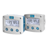
Fluidwell F018-P Manual (58 pages)
FLOW RATE INDICATOR / TOTALIZER WITH LINEARIZATION, HIGH/LOW FLOW RATE ALARMS, SCALED PULSE OUTPUT, ANALOG OUTPUT
Brand:
Fluidwell
| Category:
Measuring Instruments
| Size: 2 MB
Table of Contents
Safety Instructions
2
Disposal of Electronic Waste
2
Safety Rules and Precautionary Measures
2
About the Manual
3
Warranty and Technical Support
3
Table of Contents
4
Contents Manual
4
Introduction
6
System Description of the F018-P
6
Fig. 1: Typical Application for the F018
6
Operational
7
General Information
7
Control Panel
7
Operator Information and Functions
7
Fig. 2: Control Panel
7
Fig. 3: Example of Display Information During Process
7
Fig. 4: Example of Display Information During Programming Minimum Flow Rate
8
Fig. 5: Example of Low-Battery Alarm
8
Configuration
9
Introduction
9
Programming SETUP-Level
9
Entering SETUP-Level
9
Navigating through SETUP-Level
9
Fig. 6: SETUP Matrix Structure
9
Programming Sequence
10
Returning to OPERATOR-Level
11
Configuration Settings
11
Overview Functions SETUP Level
11
Explanation of SETUP-Menu 1 - Total
13
Explanation of SETUP-Menu 2 - Flow Rate
14
Explanation of SETUP-Menu 3 - Alarm
15
Explanation of SETUP-Menu 4 - Display
16
Explanation of SETUP-Menu 5 - Flowmeter
17
Explanation of SETUP-Menu 6 - Linearization
17
Fig. 7: Graphic Example of Linearization
18
Explanation of SETUP-Menu 7 - Analog
19
Explanation of SETUP-Menu 8 - Pulse Output
20
3.3.10 Explanation of Setup-Menu 9 - Others
20
Installation
21
General Directions
21
Installation / Surrounding Conditions
21
Handling the F-Series Enclosure
22
Identification
22
Fig. 8: Identification - Example of F0-Series Identification Label (Safe Area)
22
Fig. 9: Identification - Example of F0-Series Installation Label (Safe Area - Type PB, PX or PD)
22
Opening / Removing the Cover
23
Closing / Replacing the Cover
23
Mechanical Installation
24
Dimensions - Aluminum and Stainless Steel Enclosures
24
Fig. 10: Dimensions - Aluminum and Stainless Steel Enclosures
24
Dimensions - Non-Metallic Enclosures
25
Fig. 11: Dimensions - Non-Metallic Enclosures
25
Mounting
26
Fig. 12: Installation - Mounting Configurations
26
Electrical Installation
27
Electrical Safety
27
Protective Earth (PE) Connections
27
Field Wiring Connections
28
Fig. 13: Protective Earth (PE) Connections on Metal Enclosure
28
Power Supply Wiring
29
Sensor Supply
29
Terminal Connectors Safe Area Applications - Type PB / PX / PD
29
Fig. 14: Overview of Terminal Connectors F018-P - Type PB / PD / PX
29
Terminals 1-3: Flowmeter Input
30
Fig. 15: Terminal Connections - Coil Signal Input
30
Fig. 16: Terminal Connections - NPN Signal Input
30
Fig. 17: Terminal Connections - PNP Signal Input
31
Fig. 18: Terminal Connections - Active Signal Input
31
Fig. 19: Terminal Connections - Reed-Switch Signal Input
31
Terminal 4-5: Power Supply - Type PX (Default) and PD (Option)
32
Terminal 6: Power Supply Type PD: 8.2V Sensor Supply
32
Terminal 7-8: ALARM Output - Type OT
32
Fig. 20: Terminal Connections - NAMUR Signal Input
32
Fig. 21: Terminal Connections - Passive Transistor Output
32
Terminal 9-10: Power Supply Backlight - Type ZB (Option)
33
Terminal 11-12: Analog Output + Output Loop Power - Type AH
33
Terminal 11-12: HART Communication - Type CR (Option)
33
Fig. 22: Terminal Connections - Backlight (ZB)
33
Fig. 23: Terminal Connections - Isolated Passive 4-20Ma Signal
33
Fig. 24: Terminal Connections - HART Communication
33
Intrinsically Safe Applications
34
Identification
34
Fig. 25: Identification - Example of F0-Series Identification Label (Intrinsic Safety)
34
Fig. 26: Identification - Example of F0-Series Installation Label (Intrinsic Safety)
34
Electrical Installation in Hazardous Area
35
General Information and Instructions
35
Installations Based on FM or CSA Certificate
35
Electrical Data - Control Drawing
36
Installations Based on ATEX or Iecex Certificate
37
Electrical Data - Annex 1
38
Power Supply Wiring
39
Sensor Supply
39
Terminal Connectors Intrinsically Safe Applications
40
Fig. 27: Overview Terminal Connectors Type XI - Intrinsically Safe Applications
40
Configuration Examples Intrinsically Safe Applications
41
F018-P-AH-CR-OT-PX-XI-(ZB) - Ex Ia IIC/IIIC
41
Fig. 28: F018-P-AH-CR-OT-PX-XI-(ZB) - Ex Ia IIC/IIIC - Intrinsically Safe Application
41
F018-P-AH-CR-OT-PX-XI-ZB - Ex Ia IIC/IIIC
42
Fig. 29: F018-P-AH-CR-OT-PX-XI-ZB - Ex Ia IIC/IIIC - Intrinsically Safe Application
42
F018-P-AH-CR-OT-PD-XI-ZB - Ex Ia IIC/IIIC
43
Fig. 30: F018-P-AH-CR-OT-PD-XI-ZB - Ex Ia IIC/IIIC - Intrinsically Safe Application
43
Maintenance
44
General Directions
44
Instructions for Repair
44
Battery Replacement
45
Safety Instructions
45
Fig. 31: Marking Type PC Battery: Intrinsically Safe FW-Libat-021 (SPC02)
45
Fig. 32: Marking Type PB Battery: Safe Area Stdlibat021 (SPB02)
45
Replace the Battery
46
Disposal of Batteries
46
Fig. 33: Battery Replacement Procedure
46
Technical Specification
47
Problem Solving
50
Hart Communication
51
Declaration of Conformity
54
Index of this Manual
55
List of Figures
56
Advertisement
Fluidwell F018-P User Manual (60 pages)
FLOW RATE MONITOR / TOTALIZER WITH LINEARIZATION, HIGH/LOW FLOWRATE ALARMS, SCALED PULSE OUTPUT, ANALOG OUTPUT
Brand:
Fluidwell
| Category:
Measuring Instruments
| Size: 3 MB
Table of Contents
Table of Contents
2
About this Manual
4
How to Use this Manual
4
Use of Pictograms
4
Warranty and Technical Support
4
Model Reference
4
Safety
5
Personal Safety
5
End-User Responsibilities
5
Potential Equipment Damage
5
Disposal of Electronic Waste
5
Introduction
6
System Description
6
Product Features
6
General Characteristics
6
Input
7
Output
7
Options
7
Installation Example
7
Operation
8
Introduction
8
Operating Modes
8
Control Panel
8
Display
8
Backlight (Type ZB)
9
Displayed Information
9
Flow Rate and Total or Flow Rate
9
Clear Total
9
Accumulated Total
9
Setting Alarm Thresholds
9
Operator Alarms
10
Flow Rate Alarm
10
Low Battery
10
Internal Error
10
Configuration
11
Introduction
11
Configuring Using SETUP Mode
11
Entering SETUP Mode
11
Navigating the SETUP Menu
11
Changing Configuration Settings
12
Returning to Operator Mode
12
SETUP Menu Overview
13
SETUP Menu Explanations
14
Menu 1: Total
14
Menu 2: Flow Rate
15
Menu 3: Alarm
16
Menu 4: Display
17
Menu 5: Flowmeter
18
Menu 6: Linearization
18
Menu 7: Analog Output
20
Menu 8: Pulse Output
21
Menu 9: Others
21
Installation
22
Installation / Environmental Conditions
22
Handling the F018-P Enclosure
23
Identification
23
Opening, Assembling and Closing the F-Series
24
Mechanical Installation
25
Mechanical Dimensions
25
Mounting the F-Series
27
Electrical Installation
28
Electrical Safety
28
Protective Earth (PE) Connections
28
Field Wiring Connections
29
Power Supply
30
Sensor Supply
30
Terminal Connectors Safe Area Applications - Type PX, PD
30
Terminals 1-3 (6): Flowmeter Input
31
Terminals 4-5: Power Supply - Type PX and PD
34
Terminal 6: Sensor Power Supply - Type PD
34
Terminals 7-8: Pulse or Alarm Output - Type OT
34
Terminals 9-10: Backlight Power Supply - Type ZB
34
Terminals 11-12: Analog Output + Output Loop Power - Type AH
35
Terminals 11-12: HART Communication - Type CR
35
Intrinsically Safe Applications
36
Identification
36
Electrical Installation in Hazardous Areas
37
Installations Based on FM or CSA Certificate
37
Electrical Data - Control Drawing
38
Installations Based on ATEX or Iecex Certificate
39
Electrical Data - Annex 1
40
Terminal Connectors Hazardous Area Applications
41
Power Supply
41
Sensor Supply
42
Configuration Examples Intrinsically Safe Applications
42
F018-P-AH-CR-OT-PX-XI-(ZB) - Ex Ia IIC/IIIC
42
F018-P-AH-CR-OT-PX-XI-ZB - Ex Ia IIC/IIIC
43
F018-P-AH-CR-OT-PD-XI-ZB - Ex Ia IIC/IIIC
43
Maintenance
44
General Directions
44
Instructions for Repair
44
Battery Replacement
45
Safety Instructions
45
Battery Replacement Procedure
46
Disposal of Batteries
46
Appendix A - Technical Specification
47
General
47
Input
49
Output
49
Operational
49
Appendix B - Troubleshooting
51
Appendix C - Hart Communication
52
Appendix D - Legal Information
55
Declarations of Conformity
55
Advertisement
Related Products
Fluidwell F010-U
Fluidwell F014-P
Fluidwell F012-P
Fluidwell F010-A
Fluidwell F013-P
Fluidwell F013-A
Fluidwell F011
Fluidwell F012
Fluidwell F014
Fluidwell F016
Fluidwell Categories
Measuring Instruments
Controller
Monitor
Desktop
Touch Panel
More Fluidwell Manuals
Login
Sign In
OR
Sign in with Facebook
Sign in with Google
Upload manual
Upload from disk
Upload from URL