Omron E5CC-800 User Manual
Digital temperature controllers
Hide thumbs
Also See for E5CC-800:
- Specification & installation instructions (68 pages) ,
- Manual (68 pages)

Related Manuals for Omron E5CC-800


Summary of Contents for Omron E5CC-800
- Page 1 Introduction Preparations Digital Temperature Controllers Part Names and Basic Procedures (Simple Type) Appendices User’s Manual E5CC-800 Index E5EC-800 H211-E1-02...
- Page 3 OMRON. No patent liability is assumed with respect to the use of the information contained herein. Moreover, because OMRON is constantly striving to improve its high-quality products, the information contained in this manual is subject to change without notice.
- Page 4 WHETHER SUCH CLAIM IS BASED ON CONTRACT, WARRANTY, NEGLIGENCE, OR STRICT LIABILITY. In no event shall the responsibility of OMRON for any act exceed the individual price of the product on which liability is asserted. IN NO EVENT SHALL OMRON BE RESPONSIBLE FOR WARRANTY, REPAIR, OR OTHER CLAIMS...
- Page 5 Application Considerations SUITABILITY FOR USE OMRON shall not be responsible for conformity with any standards, codes, or regulations that apply to the combination of products in the customer's application or use of the products. At the customer's request, OMRON will provide applicable third party certification documents identifying ratings and limitations of use that apply to the products.
- Page 6 Performance data given in this manual is provided as a guide for the user in determining suitability and does not constitute a warranty. It may represent the result of OMRON's test conditions, and the users must correlate it to actual application requirements. Actual performance is subject to the OMRON Warranty and Limitations of Liability.
- Page 7 Safety Precautions Safety Precautions Definition of Precautionary Information The following notation is used in this manual to provide precautions required to ensure safe usage of the product. The safety precautions that are provided are extremely important to safety. Always read and heed the information provided in all safety precautions.
- Page 8 Safety Precautions Safety Precautions CAUTION Minor injury due to electric shock may occasionally occur. Do not touch the terminals while power is being supplied. Electric shock, fire, or malfunction may occasionally occur. Do not allow metal objects, conductors, cuttings from installation work, or moisture to enter the Digital Controller.
- Page 9 Safety Precautions CAUTION Loose screws may occasionally result in fire. Tighten the terminal screws to the specified torque of 0.43 to 0.58 N·m. Set the parameters of the product so that they are suitable for the system being controlled. If they are not suitable, unexpected operation may occasionally result in property damage or accidents.
- Page 10 Precautions for Safe Use Precautions for Safe Use Be sure to observe the following precautions to prevent operation failure, malfunction, or adverse affects on the performance and functions of the product. Not doing so may occasionally result in unex- pected events. Use the product within the specifications. •...
- Page 11 Precautions for Safe Use • A switch or circuit breaker should be provided close to Digital Controller. The switch or circuit breaker should be within easy reach of the operator, and must be marked as a disconnecting means for Digital Controller. •...
- Page 12 Installation Precautions Installation Precautions Service Life Use the Digital Controller within the following temperature and humidity ranges: Temperature: −10 to 55°C (with no icing or condensation), Humidity: 25% to 85% If the Digital Controller is installed inside a control board, the ambient temperature must be kept to under 55°C, including the temperature around the Controller.
- Page 13 Installation Precautions Waterproofing The degree of protection is as shown below. Sections without any specification on their degree of protection or those with IP@0 are not waterproof. Front panel: IP66 Rear case: IP20, Terminal section: IP00 When waterproofing is required, insert the Waterproof Packing on the backside of the front panel. The degree of protection when the Waterproof Packing is used is IP66.
- Page 14 Precautions for Operation Precautions for Operation • It takes approximately two seconds for the outputs to turn ON from after the power supply is turned ON. Due consideration must be given to this time when incorporating Digital Controllers into a control panel or similar device.
- Page 15 Preparations for Use Preparations for Use Be sure to thoroughly read and understand the manual provided with the product, and check the follow- ing points. Timing Check point Details Purchasing Product After purchase, check that the product and packaging are not dented or the product appearance otherwise damaged.
- Page 16 Revision History Revision History A manual revision code appears as a suffix to the catalog number on the front cover of the manual. H211-E1-02 Cat. No. Revision code Revision code Date Revised content March 2012 Original production June 2012 Added information on the E5CC/E5EC-@-8@@. Digital Temperature Controllers (Simple Type) User’s Manual (H211)
- Page 17 Conventions Used in This Manual Conventions Used in This Manual Differences between Standard-type and Simple-type Digital Controllers In this manual, “E5CC/E5EC” or “E5CC-800/E5EC-800” is used to indicated the E5CC/E5EC-@-8@@ Simple-type Digital Controllers. Differences in I/O Configurations E5CC E5EC Standard Standard...
- Page 18 Conventions Used in This Manual Model Notation HB alarm and HS Event inputs Communications alarm E5CC/EC-@-800 E5CC-@-801 E5CC-@-802 RS-485 E5CC/EC-@-804 RS-485 E5EC-@-808 RS-485 E5EC-@-810 Meanings of Abbreviations The following abbreviations are used in parameter names, figures, and other descriptions. These abbreviations mean the following: Symbol Term...
- Page 19 Conventions Used in This Manual How This Manual is Organized Goal Related sections Contents Learning about the Section 1 Introduction This section shows the appearance and appearance, features, describes the features, functions, and model functions, and model numbers of the E5CC/E5EC. numbers of the E5CC/E5EC Setting up the E5CC/E5EC Section 2 Preparations...
- Page 20 Conventions Used in This Manual Digital Temperature Controllers (Simple Type) User’s Manual (H211)
- Page 21 Sections in this Manual Sections in this Manual Introduction Preparations Part Names and Basic Procedures Appendices Index Digital Temperature Controllers (Simple Type) User’s Manual (H211)
-
Page 22: Table Of Contents
CONTENTS Preface ........................1 Read and Understand this Manual ................2 Safety Precautions ....................5 Definition of Precautionary Information ...................... 1-5 Symbols ..............................1-5 Precautions for Safe Use..................8 Installation Precautions..................10 Precautions for Operation ..................12 Preparations for Use ....................13 Revision History ...................... - Page 23 Section 3 Part Names and Basic Procedures Basic Application Flow ......................3-2 Power ON..........................3-3 Part Names, Part Functions, and Setting Levels ..............3-4 3-3-1 Part Names and Functions ......................3-4 3-3-2 Entering Numeric Values ......................3-7 3-3-3 Setting Levels ..........................3-8 3-3-4 E5CC/E5EC Setting Levels ......................
- Page 24 Digital Temperature Controllers (Simple Type) User’s Manual (H211)
- Page 25 Introduction 1-1 Appearance, Features, and Functions of the E5CC/E5EC ... . . 1-2 1-1-1 Appearance ........... . 1-2 1-1-2 Features .
-
Page 26: Introduction
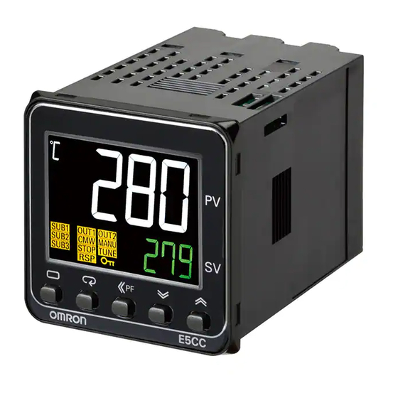
• A compact size to help downsize control panels. • Much faster sampling and greater expandability than expected in this class of Controller. • Even easier to use than previous models. E5CC-800 E5EC-800 1-1-2 Features This section compares the features of the E5CC/E5EC with the previous E5CN/E5EN Controllers. -
Page 27: Main Functions
1 Introduction 1-1-3 Main Functions This section introduces the main E5CC/E5EC functions. For details on particular functions and how to use them, refer to Section 3 Part Names and Basic Procedures and following sections. Input Sensor Types You can connect the following sensors and signals to the universal input. Thermocouple: K, J, T, E, L, U, N, R, S, B, W, PLII Resistance thermometer:... -
Page 28: I/O Configuration And Model Number Legend
1 Introduction I/O Configuration and Model Number Legend 1-2-1 I/O Configuration Inputs E5CC/E5EC Outputs Input signals Output signals Control Control output 1 Set point (SP) Limit Operation • Linear current Multi-SP • Voltage output Manipulated (for driving SSR) value • Relay •... -
Page 29: Model Number Legends
1 Introduction 1-2-2 Model Number Legends E5CC E 5 C C (3) (4) (5) (6) (3) (4) (5) (6) Meaning 48 × 48 mm Control output 1 Control output 2 Relay output None Voltage output (for driving SSR) None Linear current output None 100 to 240 VAC 24 VAC/DC... - Page 30 1 Introduction E5EC E 5 E C (3) (4) (5) (6) (3) (4) (5) (6) Meaning 48 × 96 mm Control output 1 Control output 2 Relay output None Voltage output (for driving SSR) None Linear current output None Voltage output (for driving SSR) Relay output Relay output Relay output...
-
Page 31: Preparations
Preparations 2-1 Installation ........... 2-2 2-1-1 Dimensions (Unit: mm) . -
Page 32: Installation
2 Preparations Installation 2-1-1 Dimensions (Unit: mm) E5CC (64) 48 × 48 44.8 × 44.8 E5EC (64) 2 - 2 Digital Temperature Controllers (Simple Type) User’s Manual (H211) -
Page 33: Panel Cutout (Unit: Mm)
2 Preparations 2-1-2 Panel Cutout (Unit: mm) E5CC Individual Mounting Group Mounting (48 × number of Units − 2.5) +1.0 +0.6 • Waterproofing is not possible when group mounting several Controllers. • The recommended panel thickness is 1 to 5 mm for the E5CC. •... -
Page 34: Mounting
2 Preparations 2-1-3 Mounting E5CC There are two models of Terminal Covers that you can use with the E5CC. Adapter E53-COV23 Terminal Cover E53-COV17 Adapter Terminal Cover (Sold separately.) Waterproof packing Panel Mounting to the Panel (1) For waterproof mounting, waterproof packing must be installed on the Controller. Waterproofing is not possible when group mounting several Controllers. - Page 35 2 Preparations E5EC Adapter Adapter Panel E53-COV24 Terminal Cover E53-COV24 Terminal Cover Waterproof packing Mounting to the Panel (1) For waterproof mounting, waterproof packing must be installed on the Controller. Waterproofing is not possible when group mounting several Controllers. Waterproof packing is not necessary when there is no need for the waterproofing function.
-
Page 36: Using The Terminals
2 Preparations Using the Terminals The terminal arrangements of the E5CC/E5EC are described in this section. 2-2-1 E5CC Terminal Block Wiring Example Terminal Arrangement The terminals block of the E5CC is divided into five types of terminals: control output 1, sensor input, auxiliary outputs, input power supply, and options. - Page 37 2 Preparations Terminal Details Do not connect anything to the terminals that are shaded gray. Relay output Control output 1 Control output 1 Voltage output − (for driving SSR) Control output 1 Current output − Sensor Input Model Numbers All E5CC models have universal sensor inputs, so the code in the model number is always “M.” E5CC-@@ 2 @ S M-8@@ Sensor input Terminal Details...
- Page 38 2 Preparations Auxiliary Outputs Model Numbers All E5CC models have two auxiliary outputs, so the code in the model number is always “2.” E5CC-@@ 2 @ S M-8@@ No. of auxiliary outputs Code Auxiliary outputs Specification 2 auxiliary outputs SPST-NO, 250 VAC, 3 A Terminal Details Model with 2 auxiliary outputs...
- Page 39 2 Preparations Options Model Numbers The options specification of the E5CC is given in the following location in the model number. E5CC-@@ @ @ @ M-8@@ Options Code Specification Remarks None Event inputs 1 and 2, and Communications (RS-485) The communications protocol is and CT1 CompoWay/F or Modbus-RTU.
-
Page 40: E5Ec Terminal Block Wiring Example
2 Preparations 2-2-2 E5EC Terminal Block Wiring Example Terminal Arrangement The terminals block of the E5EC is divided into five types of terminals: control outputs 1 and 2, sensor input, auxiliary outputs, input power supply, and options. Input power supply Options Control outputs 1 and 2 Not used. - Page 41 2 Preparations Terminal Details Do not connect anything to the terminals that are shaded gray. Relay output Control output 1 Voltage output Current output Control output 1 Control output 1 − − (for driving SSR) Voltage output Relay output Current output Control output 1 Control output 1 Control output 1...
- Page 42 2 Preparations Auxiliary Outputs Model Numbers All E5EC models have two auxiliary outputs, so the code in the model number is always “2.” E5EC-@@ 2 @ S M-8@@ No. of auxiliary outputs Code Auxiliary outputs Specification 2 auxiliary outputs SPST-NO, 250 VAC, 3 A Terminal Details Do not connect anything to the terminals that are shaded gray.
- Page 43 2 Preparations Options Model Numbers The options specification of the E5EC is given in the following location in the model number. E5EC-@@ @ @ @ M-8@@ Options Code Specification Remarks None Communications (RS-485), The communications protocol is and event inputs 1 and 2 CompoWay/F or Modbus-RTU.
-
Page 44: Precautions When Wiring
2 Preparations 2-2-3 Precautions when Wiring • Separate input leads and power lines in order to prevent external noise. • Use a shielded, AWG24 to AWG18 (cross-sectional area of 0.205 to 0.823 mm ) twisted-pair cable. The stripping length is 6 to 8 mm. •... - Page 45 2 Preparations Control Outputs 1 and 2 The following diagrams show the applicable outputs and their internal equivalent circuits. E5CC QX (voltage output (for RX (relay output) CX (current output) driving SSR)) − − Output type Specification Relay output SPST-NO, 250 VAC, 3 A (resistive load), Electrical durability: 100,000 operations PNP, 12 VDC ±20%, 21 mA (with short-circuit protection) Voltage output (for driving...
- Page 46 2 Preparations Output type Specification Relay output SPST-NO, 250 VAC, 5 A (resistive load), Electrical durability: 100,000 operations PNP, 12 VDC ±20%, 40 mA (with short-circuit protection) Voltage output (for driving SSR) 4 to 20 or 0 to 20 mA DC, Load: 500 Ω max., Current output Resolution: Approx.
- Page 47 2 Preparations Contact inputs Non-contact inputs Option number: 810 − − • Use event inputs under the following conditions: • The outflow current is approximately 7 mA. Contact input ON: 1 kΩ max., OFF: 100 kΩ min. No-contact input ON: Residual voltage of 1.5 V max.; OFF: Leakage current of 0.1 mA max. CT Input E5CC/E5EC models with an option number of 801, 802, 808, or 810 have one CT input.
-
Page 48: Insulation Block Diagrams
2 Preparations Insulation Block Diagrams The insulation block diagram for the E5CC/E5EC is provided in this section. Sensor input and CT input Communications and event inputs Voltage output (for driving SSR) and current output Power supply Relay outputs Auxiliary output 1 Auxiliary output 2 : Reinforced insulation : Functional insulation... - Page 49 Part Names and Basic Procedures 3-1 Basic Application Flow ......... 3-2 3-2 Power ON .
-
Page 50: Part Names And Basic Procedures
3 Part Names and Basic Procedures Basic Application Flow The following figure shows the basic flow for using the Digital Controller. Power ON Set the input type and other basic settings. • Input type • Control method • Alarm type Refer to 3-4 Procedures after Other parameters Turning ON the Power Supply. -
Page 51: Power On
3 Part Names and Basic Procedures Power ON Operation will start as soon as you turn ON the power supply to the E5CC/E5EC. The following default settings will be used when operation starts. • Input type 5: K thermocouple If the Controller is equipped with HB/HS alarm detection, it is set by default to detect heater alarms. -
Page 52: Part Names, Part Functions, And Setting Levels
3 Part Names and Basic Procedures Part Names, Part Functions, and Setting Levels 3-3-1 Part Names and Functions E5CC Front panel Temperature unit No. 1 display Operation indicators PV or specified parameter No. 2 display SP or specified parameter value Use the U D Keys to set the parameter. - Page 53 3 Part Names and Basic Procedures Displays Display Name Description E5CC: Top display No. 1 display Displays the process value or a monitor/setting item. E5EC: Top display E5CC: Bottom display No. 2 display Displays the set point or the value of a monitor/setting item. E5EC: Middle display E5CC: None No.
- Page 54 3 Part Names and Basic Procedures Keys Name Overview Description Level Key Selects the setting • In Operation Level • Press once for less than 1 second to go to level. Adjustment Level. The next setting • Press for at least 3 seconds to go to Initial Setting level depends on Level.
-
Page 55: Entering Numeric Values
3 Part Names and Basic Procedures 3-3-2 Entering Numeric Values Applying Changes to Numeric Values After you change a numeric value with the U D Keys, the changes are applied 1) when 3 seconds elapses, 2) when the M Key is pressed, or 3) when the level is changed with the O Key. Precautions for Correct Use Always make sure that any changes to numeric values are applied for one of the three methods that are given above before you turn OFF the power supply to the E5CC/E5EC. -
Page 56: Setting Levels
3 Part Names and Basic Procedures 3-3-3 Setting Levels What Are Setting Levels? On the E5CC/E5EC, the parameters are classified into levels according to their applications. These lev- els are called setting levels. The setting levels consist of some basic setting levels and other setting lev- els. -
Page 57: E5Cc/E5Ec Setting Levels
3 Part Names and Basic Procedures 3-3-4 E5CC/E5EC Setting Levels Moving between Setting Levels The following figure gives an overall image of the setting levels. The setting levels consist of the basic setting levels (shaded below) and the other setting levels (not shaded). Protect Level O + M Keys for at least 1 s... - Page 58 3 Part Names and Basic Procedures Basic Setting Levels The following figure shows the basic setting levels (shaded). Power ON Level changes automatically. Press Key once. Adjustment Level Operation Level Used to change Used for SP, alarm adjustment parameters values, and other basic (PID constants, control settings and hysteresis, etc.).
- Page 59 3 Part Names and Basic Procedures Use the following procedure to move to Advanced Function Setting Level. Power ON Level changes automatically. Step 4: Operation Level Key for at least 3 s Initial Setting Level Used to set the input Used for SP, alarm type and other basic values, and other basic...
- Page 60 3 Part Names and Basic Procedures Communications Setting Level This level is used to set the communications parameters. You can move to the Communications Set- ting Level from the Initial Setting Level. 3 - 12 Digital Temperature Controllers (Simple Type) User’s Manual (H211)
-
Page 61: Procedures After Turning On The Power Supply
3 Part Names and Basic Procedures Procedures after Turning ON the Power Supply 3-4-1 Basic Flow of Operations The basic flow of operations after you turn ON the power supply is shown below. 1. Turn ON the power supply. ↓ 2. - Page 62 3 Part Names and Basic Procedures List of Input Types Temperature range in °C Temperature range in °F Input type Specifications Set value −200 to 850 −300 to 1500 Resistance Pt100 −199.9 to 500.0 −199.9 to 900.0 thermometer 0.0 to 100.0 0.0 to 210.0 −199.9 to 500.0 −199.9 to 900.0...
- Page 63 3 Part Names and Basic Procedures Set the control method. Operation Level Operation Level Initial Setting Level Initial Setting Level in-t The display flashes. in-t (IN-T) will be displayed Press the O to show that the Initial Setting (Level) Key for at Level has been entered.
- Page 64 3 Part Names and Basic Procedures Alarm Type Numbers Alarm Alarm type Description Operation type No. Alarm function There will be no alarm outputs. Upper- and The alarm output is ON while the Example: lower-limit PV is equal to or higher than the alarm upper-limit alarm point or while Temperature...
- Page 65 3 Part Names and Basic Procedures Alarm Alarm type Description Operation type No. Absolute-value The alarm output is ON while the Example: upper-limit PV is equal to or higher than the alarm alarm value. Temperature Upper-limit alarm point (e.g., 100°C) Alarm value (e.g., 100°C) Absolute-value The alarm output is ON while the...
- Page 66 3 Part Names and Basic Procedures Alarm Alarm type Description Operation type No. PV change rate The alarm output turns ON if the alarm change in the PV within the specified calculation period Change rate width exceeds a specific width. Time PV rate of change calculation period PV Change Rate Alarm Output...
- Page 67 3 Part Names and Basic Procedures Set the set point. Operation Display Set point: 500°C (example) Press the U (Up) and D (Down) Keys and the S (Shift) Key to change the value. * Hold the U (Up) or D (Down) Key to increment or decrement the value quickly. Set the alarm set value or values.
- Page 68 3 Part Names and Basic Procedures 3 - 20 Digital Temperature Controllers (Simple Type) User’s Manual (H211)
-
Page 69: Appendices
Appendices A-1 Specifications ..........A-2 A-1-1 Ratings . -
Page 70: Specifications
A Appendices A-1 Specifications A-1-1 Ratings Supply voltage 100 to 240 VAC, 50/60 Hz 24 VAC, 50/60 Hz/24 VDC Operating voltage range 85% to 110% of rated supply voltage Option number 800: 5.2 VA max. Option number 800: 3.1 VA max./1.6 W max. E5CC Other option numbers: 6.5 VA max. -
Page 71: A-1-2 Characteristics
A Appendices A-1-2 Characteristics (±0.3% of PV or ±1°C, whichever is greater) ±1 digit max. Thermocouple (±0.2% of PV or ±0.8°C, whichever is greater) ±1 digit max. Indication accuracy Resistance (ambient temperature of thermometer 23°C) ±0.2% FS ±1 digit max. Analog input ±5% FS ±1 digit max. -
Page 72: A-1-3 Rating And Characteristics Of Options
A Appendices A-1-3 Rating and Characteristics of Options Contact Input ON: 1 kΩ max., OFF: 100 kΩ min. Event inputs Non-contact Input ON: Residual voltage 1.5 V max.; OFF: Leakage current 0.1 mA max. Transmission path: RS-485 Communications method: RS-485 (2-wire, half duplex) Communications Synchronization: Start-stop Baud rate: 9.6, 19.2, 38.4, or 57.6 kbps... -
Page 73: Current Transformer (Ct
A Appendices A-2 Current Transformer (CT) A-2-1 Specifications Item Specifications Model number E54-CT1 E54-CT3 Max. continuous current 50 A 120 A Dielectric strength 1,000 VAC (for 1 min) Vibration resistance 50 Hz, 98 m/s Weight Approx. 11.5 g Approx. 50 g Accessories None Armature (2), Plug (2) -
Page 74: Error Displays
A Appendices A-3 Error Displays When an error occurs, the error contents are shown on the No. 1 or the No. 2 display. This section describes how to check error codes on the display, and the actions to be taken to remedy the problems. - Page 75 A Appendices [[[[ Display Range Exceeded ]]]] Meaning Though this is not an error, it is displayed if the process value exceeds the display range when the control range is larger than the display range. The display ranges are shown below (with decimal points omitted). •...
- Page 76 A Appendices e111 Memory Error Meaning Internal memory operation is in error. Action First, turn the power OFF then back ON again. If the display remains the same, the Controller must be repaired. If the display is restored, then the probable cause is electrical noise affecting the control system.
-
Page 77: Troubleshooting
A Appendices A-4 Troubleshooting Checking Problems If the Digital Controller is not operating normally, check the following points before requesting repairs. If the problem persists, contact your OMRON representative for details on returning the product. Timing Status Meaning Countermeasures Turning ON... - Page 78 A Appendices Timing Status Meaning Countermeasures During Output will not turn ON Set to STOP (default: RUN) Set the RUN/STOP mode to RUN. If STOP is lit on the display, operation control is stopped. (continued) Specified operation is Select either forward or reverse operation depending on the unsuitable for required control required control.
- Page 79 A Appendices Symptom: Cannot Communicate or a Communications Error Occurs Meaning Countermeasures The communications wiring is not correct. Correct the wiring. The communications line has become Connect the communications line securely and tighten the screws. disconnected. The communications cable is broken. Replace the cable.
-
Page 80: Parameter Operation Lists
A Appendices A-5 Parameter Operation Lists A-5-1 Operation Level Parameters Characters Setting (monitor) value Display Default Unit Process Value Temperature: According to indication range for each sensor. Analog: Scaling lower limit −5% FS to Scaling upper limit +5% FS Set Point SP lower limit to SP upper limit m-sp Multi-SP Set Point... -
Page 81: A-5-2 Adjustment Level
A Appendices A-5-2 Adjustment Level Parameters Characters Setting (monitor) value Display Default Unit off, at-2, AT Execute/Cancel OFF, AT Cancel None at-1 AT-2: 100%AT Execute AT-1: 40%AT Execute cmwt Communications OFF, ON None Writing Heater Current 1 Value 0.0 to 55.0 Monitor Heater Burnout 0.0 to 50.0... -
Page 82: Initial Setting Level
A Appendices A-5-3 Initial Setting Level Parameters Characters Setting (monitor) value Display Default Unit in-t Input Type Temperature 0: Pt100 None input 1: Pt100 2: Pt100 3: JPt100 4: JPt100 5: K 6: K 7: J 8: J 9: T 10: T 11: E 12: L... - Page 83 A Appendices Parameters Characters Setting (monitor) value Display Default Unit alt1 Alarm 1Type 0: Alarm function OFF None 1: Upper and lower-limit alarm 2: Upper-limit alarm 3: Lower-limit alarm 4: Upper and lower-limit range alarm 5: Upper- and lower-limit alarm with standby sequence 6: Upper-limit alarm with standby sequence 7: Lower-limit alarm with standby sequence...
- Page 84 A Appendices Parameters Characters Setting (monitor) value Display Default Unit ev-1 none Event Input NONE: None MSP0 None stop Assignment 1 STOP: RUN/STOP manu MANU: Auto/Manual Switch prst PRST: Program Start DRS: Invert Direct/Reverse Operation at-2 AT-2: 100% AT Execute/Cancel at-1 AT-1: 40% AT Execute/Cancel wtpt...
-
Page 85: Manual Control Level
A Appendices A-5-4 Manual Control Level Parameters Characters Setting (monitor) value Display Default Unit −5.0 to 105.0 (standard) Manual MV −105.0 to 105.0 (heating/cooling) A-5-5 Advanced Function Setting Level Parameters Characters Setting (monitor) value Display Default Unit init off, fact Parameter Initialization OFF, FACT None... - Page 86 A Appendices Parameters Characters Setting (monitor) value Display Default Unit °C or °F lbal LBA Level Temperature input: 0.1 to 999.9 Analog input: 0.01 to 99.99 10.00 °C or °F lbab LBA Band Temperature input: 0.0 to 999.9 Analog input: 0.00 to 99.99 0.20 out1 Control Output 1...
-
Page 87: Protect Level
A Appendices Parameters Characters Setting (monitor) value Display Default Unit pvrp PV Rate of Change 1 to 999 Sampling Calculation Period period hctm Heating/Cooling Tuning 0: Same as heating control None Method 1: Linear 2: Air cooling 3: Water cooling ompw Minimum Output 0.0 to 50.0... -
Page 88: A-5-7 Communications Setting Level
A Appendices A-5-7 Communications Setting Level Parameters Characters Setting (monitor) value Display Default Unit psel cwf, mod Protocol Setting CWF: CompoWay/F CompoWay/ None MOD: Modbus u-no Communications Unit No. 0 to 99 None 9.6, 9.2, 38.4, Communications Baud Rate 9.6, 19.2, 38.4, or 57.6 kbps 57.6 Communications Data Length... -
Page 89: Sensor Input Setting Range, Indication Range, Control Range
A Appendices A-6 Sensor Input Setting Range, Indication Range, Control Range Specifica Input setting range Input indication range tions value −200 to 850 (°C)/−300 to 1500 (°F) −220 to 870 (°C)/−340 to 1540 (°F) Resistance Pt100 thermometer −199.9 to 500.0 (°C)/−199.9 to 900.0 (°F) −199.9 to 520.0 (°C)/−199.9 to 940.0 (°F) −20.0 to 120.0 (°C)/−40.0 to 250.0 (°F) 0.0 to 100.0 (°C)/0.0 to 210.0 (°F) -
Page 90: Setting Levels Diagram
A Appendices A-7 Setting Levels Diagram This diagram shows all of the setting levels. To move to the Advanced Function Setting Level, you must enter password. Some parameters are not displayed depending on the protect level setting and the conditions of use. Control stops when you move from the Operation Level to the Initial Setting Level. - Page 91 A Appendices Digital Temperature Controllers (Simple Type) User’s Manual (H211) A - 23...
-
Page 92: Parameter Flow
A Appendices A-8 Parameter Flow This section describes the parameters set in each level. Pressing the M Key at the last parameter in each level returns to the top parameter in that level. Power ON Starting in manual mode. Press the Key for at least 3 s. - Page 93 A Appendices Press the O Key for at least 1 s. Advanced Function Setting Level alt2 Alarm 2 Type Parameter Initialization Cold Junction init sub1 Auxiliary Output 1 Compensation Method Assignment alm1 Alarm 2 Number of Multi-SP a1on Alarm 1 ON Delay alh2 mspu Auxiliary Output 2...
- Page 94 A Appendices A - 26 Digital Temperature Controllers (Simple Type) User’s Manual (H211)
-
Page 95: Index
Index Digital Temperature Controllers (Simple Type) User’s Manual (H211) Index-1... - Page 96 indicators ............... 3-5 Initial Setting Level ............A-14 Input Error ..............A-6 AD Converter Error ............A-7 input power supply ............2-12 Adjustment Level ............A-13 input sensor types ............1-3 Advanced Function Setting Level ........A-17 inputs ................2-14 alarms (standard alarms) ..........1-3 installation ..............
- Page 97 power supply ............... 2-14 Protect Level ............... A-19 ratings ................A-2 RS-485 ..............2-17, A-4 sampling cycle ............1-2, A-3 sensor input ..............2-11 sensor input setting ranges ......... A-21 setting levels diagram ..........A-22 Shift Key (S Key) ............3-7 specifications ..............
- Page 98 Index-4 Digital Temperature Controllers (Simple Type) User’s Manual (H211)
- Page 100 The Netherlands IL 60173-5302 U.S.A. Tel: (31)2356-81-300/Fax: (31)2356-81-388 Tel: (1) 847-843-7900/Fax: (1) 847-843-7787 © OMRON Corporation 2012 All Rights Reserved. OMRON (CHINA) CO., LTD. OMRON ASIA PACIFIC PTE. LTD. In the interest of product improvement, Room 2211, Bank of China Tower, No.
Need help?
Do you have a question about the E5CC-800 and is the answer not in the manual?
Questions and answers