Omron E5CC-U Manual
Digital
Hide thumbs
Also See for E5CC-U:
- Instruction manual (2 pages) ,
- User manual (440 pages) ,
- Communications manual (224 pages)
Table of Contents
Advertisement
Quick Links
Download this manual
See also:
User Manual
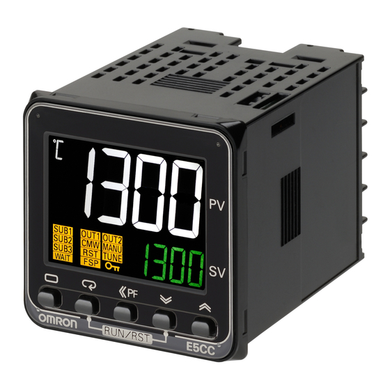
Digital Temperature Controller
E5CC-U
Large White PV Display That's Easier to Read.
Easy to Use, from Model Selection to
Setup and Operation.
A Complete Range of I/O Capacities,
Functions, and Performance.
Handles More Applications.
• The white PV display with a height of 15.2 mm improves visibility.
• High-speed sampling at 50 ms.
• Models are available with up to 2 auxiliary outputs, to cover
a wide range of applications.
• E5CC: Short body with depth of only 60 mm.
• Set up the Controller without wiring the power supply by
connecting to the computer with a Communications Conversion
Cable (sold separately). Setup is easy with the CX-Thermo (sold
separately).
Main I/O Functions
Sensor Input
Universal input
• Thermocouple
• Pt
• Analog current/voltage
Indication Accuracy
• Thermocouple input:
±0.3% of PV
• Pt input: ±0.2% of PV
• Analog input:
±0.2% of FS
Sampling Period
• 50 ms
Event Inputs
• None
Remote SP Input
• None
Serial Communications
• None
This datasheet is provided as a guideline for selecting products.
Be sure to refer to the following manuals for application precautions and other information required for operation before attempting
to use the product.
E5@C Digital Temperature Controllers User's Manual (Cat. No. H174)
E5@C Digital Temperature Controllers Communications Manual (Cat. No. H175)
(48 × 48 mm)
E5CC-U
• PF (shift) Key
• Temperature status display
• Simple programming
• Independent heating and
cooling PID control
• Changed parameter display
• Display brightness setting
Refer to your OMRON website for the most recent information on
applicable safety standards.
Refer to Safety Precautions.
Dual displays: PV/SV
Control Output 1
• Relay output
• Voltage output (for driving SSR)
• Linear current output
Control Output 2
• None
Auxiliary Outputs
• None
• 1
• 2
Transfer Output
• None
48 × 48 mm
E5CC-U
4-digit displays
1
Advertisement
Table of Contents

Related Manuals for Omron E5CC-U


Summary of Contents for Omron E5CC-U
- Page 1 • Models are available with up to 2 auxiliary outputs, to cover a wide range of applications. Refer to your OMRON website for the most recent information on • E5CC: Short body with depth of only 60 mm. applicable safety standards.
-
Page 2: Model Number Legend
E5CC-U Model Number Legend ●Plug-in Models E5CC-@@ @ @ U @ -@@@ (Example: E5CC-RW0AUM-000) −− − − − − −−− B C D E Control No. of Power Model Meaning Terminal Input outputs auxiliary supply Options type type 1 and 2... - Page 3 Note: CX-Thermo version 4.5 or higher is required for the E5CC. Refer to page 14 for the mounted dimensions. CX-Thermo version 4.61 or higher is required for the E5CC-U. For the system requirements for the CX-Thermo, refer to Waterproof Packing information on the EST2-2C-MV4 on the OMRON website (www.ia.omron.com).
-
Page 4: Specifications
Installation Category II, Pollution Class 2 (IEC 61010-1 compliant) * You cannot select a relay output or linear current output for control output 2. Note: There are no optional functions for the E5CC-U. Refer to Model Number Legend and List of Models on page 4. -
Page 5: Input Ranges
E5CC-U Input Ranges ●Thermocouple/Platinum Resistance Thermometer (Universal inputs) Sensor Platinum resistance Infrared temperature Thermocouple type thermometer sensor Sensor 10 to 60 to 115 to 140 to specifica- Pt100 JPt100 PLII 70°C 120°C 165°C 260°C tion 2300 2300 1800 1800 1700... -
Page 6: Alarm Output Operation
E5CC-U Alarm Outputs Each alarm can be independently set to one of the following 19 alarm types. The default is 2: Upper limit. (see note.) Auxiliary outputs are allocated for alarms. ON delays and OFF delays (0 to 999 s) can also be specified. - Page 7 E5CC-U With set values 1, 4 and 5, the upper and lower limit values can be set Set value: 5, Upper- and lower-limit with standby sequence independently for each alarm type, and are expressed as “L” and “H.” For Upper- and Lower-Limit Alarm Described Above *2 Set value: 1, Upper- and lower-limit alarm •...
- Page 8 *5 External communications (RS-485) and USB-serial conversion cable communications can be used at the same time. *6 The E5CC-U plug-in model is certified for UL listing only when used together with the OMRON P2CF-11 or P2CF-11-E Socket. The P3GA-11 is not certified for UL listing.
-
Page 9: Communications Functions
External Connections E5CC- UM-000 The E5CC-U is set for a K-type thermocouple (input type = 5) by default. An input error (s.err) will occur if the input Control output 1 type setting does not agree with the temperature sensor. - Page 10 : Functional isolation Nomenclature Front panel Temperature unit E5CC-U Top View of E5CC Top View of E5CC-U No. 1 display Operation indicators PV or specified parameter No. 2 display SP or specified parameter value Use the U D Keys to set the parameter.
- Page 11 Be sure to confirm this point at your site. Consider three years a rough standard.) The Waterproof Packing does not need to be attached if a waterproof structure is not required. The E5CC-U cannot be waterproofed even if the Waterproof Packing is attached.
- Page 12 E5CC-U ● Adapter Y92F-45 Note: 1. Use this Adapter when the Front Panel has already been prepared for the E5B@. 2. Only black is available. 3. You cannot use the E58-CIFQ2 USB-Serial Conversion Cable if you use the Y92F-45 Adapter. To use the USB-Serial Conversion Cable to make the settings, do so before you mount the Temperature Controller in the panel.
- Page 13 Please use it for the mis-operation This Protective Cover is soft type. prevention etc. It is able to operate the controller with using this cover. ● E5CC-U Wiring Socket Front-connecting Socket P2CF-11 Terminal Layout/Internal Connections Eleven, M3.5 × 7.5 (Top View)
-
Page 14: Operation
E5CC/E5CC-U/E5EC/E5AC/E5DC Operation Setting Levels Diagram This diagram shows all of the setting levels. To move to the advanced function setting level and calibration level, you must enter passwords. Some parameters are not displayed depending on the protect level setting and the conditions of use. - Page 15 E5CC/E5CC-U/E5EC/E5AC/E5DC Error Displays (Troubleshooting) When an error occurs, the No. 1 display or No. 2 display shows the error code. Take necessary measure according to the error code, referring the following table. Display Name Meaning Action Operation After the error occurs and it is...
-
Page 16: Operation Level
E5CC/E5CC-U/E5EC/E5AC/E5DC Operation Parameters The following pages describe the parameters set in each level. Pressing the M (Mode) Key at the last parameter in each level returns to the top parameter in that level. Some parameters may not be displayed depending on the model and other settings. -
Page 17: Monitor/Setting Item Level
E5CC/E5CC-U/E5EC/E5AC/E5DC Monitor/Setting Item Level Monitor/Setting Monitor/Setting Monitor/Setting Monitor/Setting Monitor/Setting Item Display 1 Item Display 4 Item Display 5 Item Display 3 Item Display 2 Note: The monitor/setting items to be displayed is set in the Monitor/Setting Item 1 to 5 parameters (advanced function setting level). -
Page 18: Safety Precautions
*4. The specified torque is 0.5 N·m for the E5CC-U. Do not use the Digital Temperature Controller where subject to flammable or explosive gas. Otherwise, minor injury from explosion may occasionally occur. - Page 19 Use the specified size of crimped terminals (M3.5, width of 7.2 mm 25.Do not bend the communications cables past their natural bending or less) to wire the E5CC-U. To connect bare wires to the terminal radius. Do not pull on the communications cables.
-
Page 20: Application Conditions
E5CC-U 3. Mount the product so that it is horizontally level. For the Wiring Socket for the E5CC-U, purchase the P2CF-11 or 4. If the measurement accuracy is low, check to see if input shift has been set correctly. -
Page 21: Scope Of Guarantee
AWG14 (cross-sectional area of 0.205 to 2.081 mm ) twisted-pair cable for the E5CC-U. The stripping length is 6 to 8 mm for the E5CC, E5EC, E5AC, or E5DC and 5 to 6 mm for the E5CC-U. • Use crimp terminals when wiring the terminals. - Page 22 MEMO...
-
Page 23: Terms And Conditions Of Sale
Buyer indemnifies Omron against all related costs or expenses. rights of another party. 10. Force Majeure. Omron shall not be liable for any delay or failure in delivery 16. Property; Confidentiality. Any intellectual property in the Products is the exclu-... - Page 24 OMRON ELETRÔNICA DO BRASIL LTDA • HEAD OFFICE São Paulo, SP, Brasil • 55.11.2101.6300 • www.omron.com.br OMRON EUROPE B.V. • Wegalaan 67-69, NL-2132 JD, Hoofddorp, The Netherlands. • +31 (0) 23 568 13 00 • www.industrial.omron.eu Authorized Distributor: Automation Control Systems •...
- Page 25 Mouser Electronics Authorized Distributor Click to View Pricing, Inventory, Delivery & Lifecycle Information: Omron E5CC-RW0AUM-000 E5CC-CX1AUM-000 E5CC-QX0DUM-000 E5CC-CX2DUM-000 E5CC-QX2AUM-000 E5CC- QX0AUM-000 E5CC-RW1DUM-000 E5CC-RW1AUM-000 E5CC-CX2AUM-000 E5CC-QX2DUM-000 E5CC- CX0AUM-000 E5CC-RW2DUM-000 E5CC-CX1DUM-000 E5CC-RW0DUM-000 E5CC-RW2AUM-000 E5CC- QX1DUM-000 E5CC-CX0DUM-000...
Need help?
Do you have a question about the E5CC-U and is the answer not in the manual?
Questions and answers