Omron E5CC-T Manual
Programmable temperature controller (digital controller)
Hide thumbs
Also See for E5CC-T:
- Instruction manual (2 pages) ,
- User manual (438 pages) ,
- Communications manual (186 pages)
Table of Contents
Advertisement
Quick Links
Programmable Temperature Controller (Digital Controller)
E5CC-T
Programmable Controllers Join the E5 C Series!
Program up to 256 segments can handle a wide
variety of applications.
• Set up to 8 Programs (Patterns) with 32 Segments (Steps) Each
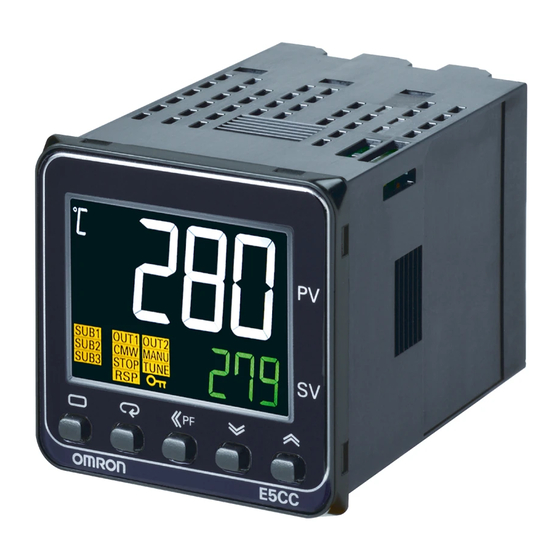
• The white PV display with a height of 15.2 mm improves visibility.
• High-speed sampling at 50 ms.
• Models are available with up to 3 auxiliary outputs, up to 4 event
inputs, and a transfer output to cover a wide range of applications.
• Short body with depth of only 60 mm.
• Set up the Controller without wiring the power supply by connecting to
the computer with a Communications Conversion Cable (sold
separately). Setup is easy with the CX-Thermo (sold separately).
• Easy connections to a PLC with programless communications. Use
component communications to link Temperature Controllers to each
other.
Main I/O Functions
Sensor Input
Universal input
• Thermocouple
• Pt
• Analog current/voltage
Indication Accuracy
• Thermocouple input: ±0.3%
of PV
• Pt input: ±0.2% of PV
• Analog input: ±0.2% of FS
Sampling Period
• 50 ms
Event Inputs
• None
• 2
• 4
Serial Communications
• None
• RS-485
This datasheet is provided as a guideline for selecting products.
Be sure to refer to the following manuals for application precautions and other information required for operation before attempting
to use the product.
E5@C-T Digital Temperature Controllers Programmable Type User's Manual (Cat. No. H185)
E5@C-T Digital Temperature Controllers Programmable Type Communications Manual (Cat. No. H186)
(48 × 48 mm)
E5CC-T
• PF (shift) Key
• Temperature status display
• Operating and editing the program
• Independent heating and cooling
PID control
• Parameter mask setting
• Display brightness setting
48 × 48 mm
E5CC-T
Refer to your OMRON website for the most recent
information on applicable safety standards.
Refer to Safety Precautions on page 90.
E5CC-T is scheduled to be released in January, 2014.
4-digit displays
Dual displays: PV/SV
Control Output 1
• Relay output
• Voltage output (for driving
SSR)
• Linear current output
Control Output 2
• None
• Voltage output (for driving
SSR)
Auxiliary Outputs
• 3
Transfer Output
• None
• 1
1
Advertisement
Table of Contents

Subscribe to Our Youtube Channel
Related Manuals for Omron E5CC-T


Summary of Contents for Omron E5CC-T
- Page 1 • Easy connections to a PLC with programless communications. Use component communications to link Temperature Controllers to each Refer to Safety Precautions on page 90. other. E5CC-T is scheduled to be released in January, 2014. Main I/O Functions E5CC-T Sensor Input Universal input •...
-
Page 2: Heating And Cooling Control
E5CC-T Model Number Legend and Standard Models Model Number Legend ●Models with Screw Terminals E5CC-T @@3 @5 M @@@ (Example: E5CC-TRX3A5M-000) −−−−−− −−− A BC D E No. of Power Model Meaning Control outputs Terminal Input auxiliary supply Options 1 and 2... - Page 3 E53-COV23 EST2-2C-MV4 Note: The Terminal Covers E53-COV23 are provided with the Digital Note: CX-Thermo version 4.61 or higher is required for the E5CC-T. Temperature Controller. The E53-COV10 cannot be used. For the system requirements for the CX-Thermo, refer to Refer to page 61 for the mounted dimensions.
- Page 4 E5CC-T Specifications Ratings A in model number: 100 to 240 VAC, 50/60 Hz Power supply voltage D in model number: 24 VAC, 50/60 Hz; 24 VDC Operating voltage range 85% to 110% of rated supply voltage Power consumption 7.5 VA max. at 100 to 240 VAC, and 4.1 VA max. at 24 VAC or 2.3 W max. at 24 VDC...
-
Page 5: Input Ranges
E5CC-T Input Ranges ●Thermocouple/Platinum Resistance Thermometer (Universal inputs) Sensor Platinum resistance Infrared temperature Thermocouple type thermometer sensor Sensor 10 to 60 to 115 to 140 to specifica- Pt100 JPt100 PLII 70°C 120°C 165°C 260°C tion 2300 2300 1800 1800 1700... -
Page 6: Alarm Types
E5CC-T Alarm Types Each alarm can be independently set to one of the following 17 alarm types. The default is 2: Upper limit. (see note.) Auxiliary outputs are allocated for alarms. ON delays and OFF delays (0 to 999 s) can also be specified. - Page 7 E5CC-T With set values 1, 4 and 5, the upper and lower limit values can be set Set value: 5, Upper- and lower-limit with standby sequence independently for each alarm type, and are expressed as “L” and “H.” For Upper- and Lower-Limit Alarm Described Above *2 Set value: 1, Upper- and lower-limit alarm •...
- Page 8 Memory protection Non-volatile memory (number of writes: 1,000,000 times) Setup Tool CX-Thermo version 4.61 or higher E5CC-T top panel: An E58-CIFQ2 USB-Serial Conversion Cable is used to connect to a USB port on Setup Tool port the computer. *5 Approved standards...
-
Page 9: Program Control
E5CC-T Program Control Number of programs (patterns) Number of segments (steps) Time setting (Segment set with set point and time.) Segment setting method Slope setting (Segment set with segment type, set point, slope, and time.) 0 h 0 min to 99 h 59 min... - Page 10 E5CC-T USB-Serial Conversion Cable When Digital Temperature Controllers are con- nected, set points and RUN/STOP commands can be sent from the Digital Temperature Control- Applicable OS Windows XP, Vista, or 7 Component ler that is set as the master to the Digital Temper- Applicable software CX-Thermo version 4.61 or higher...
-
Page 11: External Connections
Voltage output Terminal type (for driving SSR) Auxiliary outputs 12 VDC, 21 mA The E5CC-T is set for a K-type thermocouple (input Control output 2 Linear current output Relay output type = 5) by default. An input error (s.err) will occur... - Page 12 Front panel Temperature unit Operation indicators No. 1 display PV or specified monitor/setting parameter Top View of E5CC-T No. 2 display Press O Key once to go to SP or specified monitor/parameter value Program Setting Level. Top-panel Setup Tool port...
- Page 13 E5CC-T Accessories (Order Separately) ● USB-Serial Conversion Cable E58-CIFQ2 (2110) 1510 LED (RD) USB connector (type A plug) Serial connector LED (PWR) LED (SD) ● Terminal Covers ● Terminal Covers E53-COV17 E53-COV23 (Three Covers provided.) 48.8 Terminal Cover (E53-COV23) 44.8 ●...
-
Page 14: Connection Example
Thru-current (Io) vs. Output Voltage (Eo) Two, M3 (depth: 4) (Reference Values) E54-CT3 Maximum continuous heater current: 120 A (50/60 Hz) (Maximum continuous heater current for an OMRON Digital Temperature Controller is 50 A.) ± Number of windings: E54-CT3 Accessories ±... - Page 15 Y92F-30 (Accessory) 72 × 72 48 × 48 62.8 To back of the E5CC-T ● DIN Track Mounting Adapter Y92F-52 Note: This Adapter cannot be used together with the Terminal Cover. Remove the Terminal Cover to use the Adapter. This Adapter is used to mount the E5CC-T to a DIN Track.
- Page 16 E5CC-T E5CC-T ● Watertight Cover ● Mounting Adapter Y92A-48N Y92F-49 21.9 The Mounting Adapter is provided with the Temperature Controller. Order this Adapter separately if it becomes lost or damaged. 87.7 79.2 67.6 ● Protective Cover ● Protective Cover Y92A-48H...
- Page 17 E5@C/E5@C-T E5 C-T This diagram shows all of the setting levels. To move to the advanced function setting level and calibration level, you must enter passwords. Some parameters are not displayed depending on the protect level setting and the conditions of use. Press O and M Keys Protect Level for at least 1 s.
- Page 18 E5@C/E5@C-T E5@C-T Some parameters may not be displayed depending on the model and other settings. Starting in manual mode Monitor/Setting Item Level PF Monitor/ Power ON PF Monitor/Setting Manual Control Level Setting Item Item display 2 to 5 display 1 * The monitor/setting items to display are set in the Monitor/Setting Item 1 to 5 parameters PV/Manual MV (Advanced Function Setting Level).
- Page 19 E5@C/E5@C-T Press O Key Protect Level for at least 1 s. Press O + M Key for at least 3 s. Operation/Adjustment pmov oapt pfpt PF Key Protect Protect Move to Protect Level Initial Setting/ Parameter Mask Enable icpt pmsk Press O + M Key for at least 3 s.
- Page 20 E5@C/E5@C-T Advanced Function Setting Level Direct Setting of Position init mant pmvd Manual Output Method Proportional MV Parameter Initialization hold PV Rate of Change mani pvrp pend Manual MV Initial Value Program End ON Time Calculation Period hctm Heating/Cooling Tuning Standby Time Unit Method ompw...
- Page 21 E5@C/E5@C-T Error Displays (Troubleshooting) When an error occurs, the No. 1 display or No. 2 display shows the error code. Take necessary measure according to the error code, referring the following table. Display Name Meaning Action Operation After the error occurs and it is The input value exceeded the control Check the wiring for input to be sure displayed, the alarm output will...
-
Page 22: Safety Precautions
E5@C/E5@C-T Safety Precautions ● Be sure to read the precautions for all E5@C/E5@C-T models in the website at: http://www.ia.omron.com/. Warning Indications Minor electric shock or fire may occasionally occur. Indicates a potentially hazardous Do not use any cables that are damaged. -
Page 23: Precautions For Safe Use
E5@C/E5@C-T Precautions for Safe Use Be sure to observe the following precautions to prevent malfunction product. If power is turned ON to the product before turning ON power to the load, self-tuning will not be performed properly and or adverse affects on the performance or functionality of the product. optimum control will not be achieved. - Page 24 The E5CC-U cannot be waterproofed even if the Waterproof Packing period will vary with the operating environment. Check the required is inserted. 2. Insert the E5CC/E5CC-U/E5CC-T into the mounting hole in the period in the actual application. Use 3 years or sooner as a guideline. panel.
-
Page 25: Removing The Main Unit
E5@C/E5@C-T E5EC/E5AC/E5EC-T/E5AC-T from the Terminal Unit. Adapter Adapter Panel Terminal Cover (E53-COV24) Terminal Cover (E53-COV24) Water Proof Packing 1. For waterproof mounting, waterproof packing must be installed on End Plate Installation the Controller. Waterproofing is not possible when group mounting Make sure to attach PFP-M End Plates to the ends of the Units. -
Page 26: Mounting The Terminal Cover
Tighten the screws to a torque of 0.29 to 0.39 N·m. Mounting the Terminal Cover E5CC/E5CC-T Slightly bend the E53-COV23 Terminal Cover to attach it to the terminal block as shown in the following diagram. The Terminal Cover Double-sided tape cannot be attached in the opposite direction. -
Page 27: Scope Of Guarantee
AWG14 (cross-sectional area of 0.205 to 2.081 mm ) twisted-pair cable for the E5CC-U. The stripping length is 6 to 8 mm for the E5CC, E5EC, E5AC, E5DC, or E5CC-T and 5 to 6 mm for the E5CC-U. • Use crimp terminals when wiring the terminals. - Page 28 MEMO...
-
Page 29: Terms And Conditions Of Sale
Buyer indemnifies Omron against all related costs or expenses. rights of another party. 10. Force Majeure. Omron shall not be liable for any delay or failure in delivery 16. Property; Confidentiality. Any intellectual property in the Products is the exclu-... - Page 30 OMRON ELETRÔNICA DO BRASIL LTDA • HEAD OFFICE São Paulo, SP, Brasil • 55.11.2101.6300 • www.omron.com.br OMRON EUROPE B.V. • Wegalaan 67-69, NL-2132 JD, Hoofddorp, The Netherlands. • +31 (0) 23 568 13 00 • www.industrial.omron.eu Authorized Distributor: Automation Control Systems •...
- Page 31 Mouser Electronics Authorized Distributor Click to View Pricing, Inventory, Delivery & Lifecycle Information: Omron E5CC-TCQ3D5M-000 E5CC-TCX3A5M-004 E5CC-TQQ3A5M-005 E5CC-TRX3A5M-006 E5CC-TQX3A5M-003 E5CC-TCQ3A5M-006 E5CC-TRX3D5M-001 E5CC-TQX3A5M-000 E5CC-TCQ3D5M-005 E5CC-TCQ3D5M-006 E5CC-TRX3D5M-003 E5CC-TQX3A5M-006 E5CC-TQQ3A5M-006 E5CC-TCX3A5M-000 E5CC-TQX3D5M-000 E5CC-TQQ3D5M-000 E5CC-TQQ3D5M-005 E5CC-TRX3A5M-003 E5CC-TQX3D5M-006 E5CC-TCX3D5M-006 E5CC-TQQ3A5M-000 E5CC-TCQ3A5M-001 E5CC-TRX3A5M-005 E5CC-TQX3A5M-005 E5CC-TQX3D5M-003 E5CC-TRX3D5M-000 E5CC-TQQ3A5M-003 E5CC-TCQ3A5M-005 E5CC-TCX3A5M-006 E5CC-TQX3D5M-005...
Need help?
Do you have a question about the E5CC-T and is the answer not in the manual?
Questions and answers