Table of Contents
Advertisement
Quick Links
Advertisement
Table of Contents

Subscribe to Our Youtube Channel
Related Manuals for Diamond Products CC6561


Summary of Contents for Diamond Products CC6561
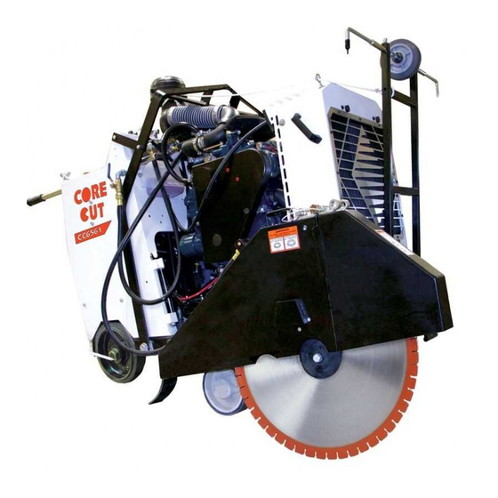
- Page 1 CORE CUT OPERATOR’S MANUAL CC6561 & CC6561-3 MARCH, 2023 Part #: 1804006-01...
-
Page 3: Table Of Contents
Dimensions ..............14 Spot Light ..............36 Specifications ..............15 Parking Brake ............... 36 Operating the CC6561 and CC6561-3 ......16 Engaging the Parking Brake ........36 Handlebars ..............16 Disengaging the Parking Brake ........ 36 Adjusting the Handlebars ........16 Maintaining the CC6561 and CC6561-3 ....... - Page 4 Changing the Oil - Single Speed ......43 Changing Oil - Three Speed ......... 44 Draining Heat Exchanger – Freezing Temps ..45 Hydraulic System ............45 Adding Hydraulic Fluid.......... 45 Rear Drive Transmission .......... 46 Cooling Fan ............46 Adding Oil .............
-
Page 5: Safety Precautions
Safety Precautions Proposition 65 WARNING Operate the CC6561 Concrete Saw and CC6561-3 Engine exhaust and some of its constituents are Concrete Saw and all of their components according to this manual. Failure to comply with known to the State of California to cause cancer, and understand the following safety, operations, birth defects, and/or other reproductive harm. -
Page 6: General Safety
General Safety DO NOT: • Drop equipment, supplies, tools, etc., when • Read and understand all of the safety, handling to help prevent injuries. operations, and maintenance instructions • Operate the saw around combustible materials provided in this manual prior to operating or or fumes to prevent fires/explosions. -
Page 7: Battery And Electrical Safety
Battery and Electrical Safety • Inspect the blade flanges for damages, wear, and cleanliness. Clean or replace • Ignitable explosive gases are dirty/damaged components immediately. emitted from the battery. DO • DO NOT expose yourself or anyone NOT expose the battery to else to the direct line of the blade sparks or open flames. -
Page 8: Fuel Safety
• Make sure the speed control lever (applicable • Always pivot the front of the blade models) is at Neutral when starting the engine. guard 180° (fully upward) so the • Fill the fuel tank and check the oil level prior to guard does not swing down starting the engine. -
Page 9: Cutting Safety
Cutting Safety • Squealing belts indicate looseness. • DO NOT use old and new belts on the same • The direct work area should not contain buried sheave together. or embedded electrical, gas, or water lines that could be damaged and/or cause personal injury Transmission Safety while cutting. -
Page 10: Lifting Safety
Lifting Safety • Move yourself and all others away from the lifting area when hoisting the saw to prevent being crushed. Secure the appropriate hoisting cables, straps, and/or chains to the saw’s designated lift points prior to hoisting. DO NOT attempt to lift the saw irresponsibly and/or improperly. -
Page 11: Introducing The Cc6561
Introducing the CC6561 Components Figure 1: Side Views of CC6561 1. Frame Upright 13. Lift Frame 25. PTO 2. Instrument Panel 14. Frame Base 26. Rotary Tensioner 3. Control Lever 15. Rear Drive Assembly 27. Transmission 4. Control Grip 16. Eaton Transmission Jackshaft 5. -
Page 12: Introducing The Cc6561-3
Introducing the CC6561-3 Components Figure 2: Side Views of CC6561-3 1. Frame Upright 13. Lift Frame 25. PTO 2. Instrument Panel 14. Frame Base 26. Rotary Tensioner 3. Control Lever 15. Rear Drive Assembly 27. Transmission 4. Control Grip 16. Eaton Transmission Jackshaft 5. -
Page 13: Controls
Controls Figure 3: Saw Controls 1. Ignition Switch–Starts engine. 2. Engine Throttle Rocker–Increases and decreases engine speed/blade speed (RPM). 3. Engine Display Panel – Displays specific engine information; speed (RPM), fuel level, temperature, etc. 4. Parking Brake Lever- Engages and disengages the wheel brake 5. -
Page 14: Dimensions
Dimensions Figure 4: Side and Bottom View... -
Page 15: Specifications
Specifications Table 1: Saw Specifications Maximum Cutting Depth 17-3/4” with 42” blade Blade Shaft Diameter 2” Arbor Diameter 1” with driven pin Blade Shaft Bearings Oil Filled Blade Shaft Drive 10 V-Belts Blade Mounting Right or left Blade Raise/Lower Electro-hydraulic pump Blade Coolant Dual multi-spray water tubes Blade Guard Attachment... -
Page 16: Operating The Cc6561 And Cc6561-3
Operating the CC6561 and CC6561-3 front side of the blade. Holding the string ends Handlebars in one hand, tension the lines out toward the The handlebars help the operator guide and front pointer rod. maneuver the saw. Adjusting the Handlebars Loosen both handle lock knobs. -
Page 17: Rear Pointers
Rear Pointers Diamond Blades The rear pointer rods act as guides when cutting. WARNING Adjusting the Rear Pointers DO NOT exceed the blade’s maximum recommended speed when cutting. Excessive blade speeds can cause blade breakage, resulting in serious injuries and/or death. Using the proper blade (size and type) preserves the blade and improves cutting and operator efficiency, resulting in lower costs. -
Page 18: Blade Speed
Blade Speed CAUTION Refer to the CC6561 or CC6561-3 RPM Chart, the Wear gloves and be alert to the surrounding blade, or the blade packaging information for the environment when handling blades. recommended blade speeds when cutting. DO NOT exceed the maximum recommended blade speed. - Page 19 Figure 12: Lock Pin through Rear Hinge Figure 14: Second Lock Pin through Ring of First Lift up the front half of the blade guard until the Right Side of Saw and Left Side (less than 26” to 42”) front hinge knuckles contact this lock pin. (Note: Mounted Blade Guards This prevents the front half of the guard from contacting the engine DPF canister.) Secure by...
-
Page 20: Removing The Blade
Remove the blade shaft bolt using the wrench. Slightly rotate the outer flange and blade Turn the bolt clockwise (left-hand threads) on backward to eliminate backlash (looseness) the right side of the saw, and counterclockwise between parts. (right-hand threads) on the left side of the saw. Place the wedge lock washer onto the blade Remove the bolt and wedge lock washer, and shaft bolt and insert the bolt into the blade... -
Page 21: Blade Guard
5. Inspect the bolt, outer flange, inner flange, and inner flange alignment pin hole for visible damages and clean, repair, or replace as necessary. 6. Align and fit the outer flange alignment pin and shaft into the blade shaft and inner flange alignment pin hole. -
Page 22: Removing The Blade Guard
Removing the Blade Guard 1. Disconnect the water supply hose from the blade guard hose fitting. 2. Remove the lock pin from the tapered blade guard mount hole. 3. For the 36-42” blade guard; remove the blade guard cap screw from the threaded hole on the side of the frame base and from the blade guard. -
Page 23: Water Safety Switch
Figure 25: Left Water Valve Figure 27: Control Grip Raising the Saw Press the control grip’s left pushbutton to raise the saw and release to stop. Note: Raise the blade when maneuvering the saw to provide proper clearance between the blade and the ground. Lowering the Saw Press the control grip’s right pushbutton to lower the saw and release to stop. -
Page 24: Speed Control Lever
Speed Control Lever The engine must run at half throttle or greater for proper transmission efficiency when maneuvering The speed control lever places the saw in neutral the saw with power. (no movement), forward, or reverse. Note: The engine must be running and the transmission must be engaged to move the saw using the speed control lever, which should be in Neutral when starting the engine. -
Page 25: Fuel System
Adding Fuel Check the fuel level daily and fill as necessary. 1. Lower the saw to the ground so it is level. 2. Stop the engine and let it cool down. 3. Remove the fuel tank cap. Figure 31: Transmission Lever 4. -
Page 26: Display Panel
Turning the ignition switch to run or start will activate the display panel. A sequence of screens will display on the control panel. First you will see a notation in the upper left corner, “Booting”, followed by Diamond Products logo and then the gauge screen. If one or more of the emergency stop triggers are activated, the E-stop switch is active, coolant level is low, or back panel is open (on certain models) an emergency shutdown window will be displayed. -
Page 27: Soft Keys (Buttons)
Soft Keys (Buttons) The Soft Key choices are associated with the throttle source. These will appear on the bottom of the display screen and can be selected by pushing the button directly below the soft key. Soft Key Description Freeze Frame – Requests the freeze frame data from the ECU when faults are present. -
Page 28: Status Icons
Status Icons The Status Icons are color coded and light up when communicating to the operator. Pay close attention to any Status Icons and color if it appears. Status Icon Description Check Engine – Yellow icon is visible if the controller receives a DM1 (Active Diagnostic Trouble Code) message with an amber lamp command. -
Page 29: Main Menu
Main Menu To return to Main Menu select the soft key below The Main Menu is the default gauge screen the Arrow or the soft key below Main Menu icon (Home). There are two soft key options available then using the up and down arrows place cursor on from the Main Menu: Gauges and select the soft key under ( Arrow... -
Page 30: Gauges
appropriate Suspect Parameter Number (SPN) and Failure Mode Indicator (FMI), Text Description (if available) and the ID/Name of the device that transmitted the DM1 message. Press the UP/DOWN soft keys to reach the next diagnostic in the list. Figure 37: Main Menu Action Items – Screen 2 Gauges Returns screen to Main Menu Diagnostics... -
Page 31: System Information
System Information Scroll through the Menu list using the UP/DOWN soft keys, and stop the cursor next to the action item System Info. To select, press ( ) soft key. The screen displays the following items: • Engine Model • Engine Serial Number •... -
Page 32: User Settings
User Settings Scroll through the Menu list using the UP/DOWN soft keys, and stop the cursor next to the action item User Settings - To select, press ( ) soft key. The screen displays the following action items: • Colors •... -
Page 33: Automatic Shutdown
Language Units Using the UP/DOWN soft keys stop the cursor next Using the UP/DOWN soft keys stop the cursor next to the action item, Language. Set your language to the action item, Units. Set your unit preference preference using the +/– soft keys. using the +/–... -
Page 34: Engine
Engine Starting the Engine WARNING WARNING • DO NOT expose yourself or anyone DO NOT use any other starter else to the direct line of the blade when substances or starter fluids when operating the saw. starting the engine using the glow •... -
Page 35: Stopping The Engine
Stopping the Engine Align the front pointer with the blade. Clearly mark the cutting line. The work area should not contain buried or CAUTION embedded electrical, gas, or water lines. DO NOT leave the saw unattended until the ... -
Page 36: Adjusting The Depth Stop
Parking Brake Adjusting the Depth Stop Turn the depth stop knob counterclockwise to increase the cutting depth, or turn the depth stop The parking brake stops the saw from moving knob clockwise to decrease the cutting depth. The forward or backward unintentionally, and is helpful depth stop knob will stop turning when the saw has on steeper slopes and hills. -
Page 37: Maintaining The Cc6561 And Cc6561-3
Synthetic, 3 qts) supervised by an experienced person. 500 Hours • Change engine oil, only use SAE 10W-30. Refer to the CC6561 and CC6561-3 Parts’ Lists for • Replace oil filter cartridge. additional information and part diagrams when • Replace in-line fuel filter. -
Page 38: Front Axle
Front Axle Rear Wheels Lubricate the front axle grease fitting every 40 Inspect the rear wheels regularly for damages or hours of operation. Lubricate both pillow block wear and replace as necessary. bearing grease fittings every 40 hours of operation. 1. -
Page 39: Battery Type
Battery Type Electrical System 12 Volt, (700 CCA) Group 34 Servicing the Battery WARNING DO NOT perform maintenance 1. Remove the battery brace lock nuts and battery on the electrical system without brace. first disconnecting the battery. Always use the correct size fuses (amps) to prevent fires. -
Page 40: Magnetic Sensor
Magnetic Sensor Replacing the Magnetic Sensor Disconnect the battery. The magnetic sensor transfers the blade RPM to Disconnect the magnetic sensor’s two-wire the blade tachometer/hour meter. If the blade connector. tachometer/hour meter remains at zero when Loosen the jam nut on the magnetic sensor, operating the saw, the magnetic sensor needs to and turn the sensor counterclockwise to remove be adjusted or replaced. -
Page 41: Restriction Indicator
Restriction Indicator Pull out the tab on the air cleaner’s end cover. Figure 58: Restriction Indicator 1. Service the air cleaner when the restriction Figure 60: End Cover Tab indicator turns red. 2. Press the restriction indicator reset button on Turn the end cover clockwise to unlock the the top of the indicator to reset the unit after the cover and pull the end cover away from the... -
Page 42: Replacing The Inner Safety Filter
Figure 61: Outer Primary Filter Figure 62: Inner Safety Filter Place the end cover tightly up against the 6. Place the outer primary filter into the air ridge at the end of the air cleaner. cleaner (over the inner safety filter) and Turn the end cover counterclockwise to lock gently push the filter into the unit until it the cover onto the air cleaner. -
Page 43: Drive Alignment
Remove tools from the area. Start the engine to check the speed control lever for accuracy. Turn the engine off and readjust the threaded nuts as necessary. Adjust the cap screw at the speed control lever’s pivot point to change the amount of friction felt when moving the speed control lever. -
Page 44: Changing Oil - Three Speed
Figure 68: ½ʺ Casing Drain Plug 4. Remove the 3/8” overflow pipe plug from the Figure 66 Single Speed Blade Shaft right hand side cover of the transmission. Assembly A – Casing vent line B – Oil drain plug 8. Add automatic transmission fluid into the expansion tank up to the Full Cold line. -
Page 45: Draining Heat Exchanger - Freezing Temps
7. Continue filling the expansion tank with the SAE Hydraulic System 75W-90 synthetic gear oil or equivalent up to the level of the overflow pipe plug. WARNING 8. Replace the overflow plug. Turn the engine off prior to performing 9. Remove oil pan from beneath the saw. maintenance on the hydraulic system. -
Page 46: Rear Drive Transmission
Touch the sonic tension meter sensor (can be transmission forward in the platform slots. ordered through Diamond Products) to the midpoint Leave a little bit of slack in the chain, and of the longest belt section and strum the belt. - Page 47 Three Speed Adjusting the Blade Drive Belts Inspect the belts for fraying, stress cracks, Single Speed and/or breakage and replace immediately if there are damages. Inspect the belts for fraying, stress cracks, Test the belt tension. Proceed to step 3 if the and/or breakage and replace immediately if belts need tensioning.
-
Page 48: Replacing The Blade Drive Belts
Replacing the Blade Drive Belts Single Speed 1. Locate the belt guard on the left side of the saw. Loosen and remove the seven hex head cap screw and bolts located on the side and rear of saw. Remove belt guard. 2. -
Page 49: Primary Transmission V-Belt
Once the blade drive belts are tightened properly, lock the detent pin. Turn detent pin until it snaps back into place. Replace belt guard and retighten the seven hex head cap screw and bolts. Primary Transmission V-Belt Inspect the V-belt regularly for fraying, stress cracks, and/or breakage and replace immediately if there are damages. -
Page 50: Rotary Tensioner
estimate the number of degrees the rotary Rotary Tensioner tensioner should move for proper alignment. 8. Pull the rotary tensioner knob up and Adjusting the Rotary Tensioner remove the belt from the rotary tensioner 1. Remove Belt Guard idler pulley. 2. -
Page 51: Engine
Engine WARNING Let the engine cool down prior to performing maintenance. Always refer to the engine operator’s manual as the primary source for information on the engine, including maintenance and servicing! Engine Cooling System Cooling Fan Inspect and clean the engine cooling system regularly depending on the level of concrete dust and debris at work sites. -
Page 52: In-Line Fuel Filter
Storing In-Line Fuel Filter Complete the tasks listed below prior to storing the saw for longer time frames: Replace the in-line fuel filter every 250 to 500 hours depending on the amount of sediment in the filter. • Lower the saw completely to remove strain on the lifting mechanism. -
Page 53: References
References Appendix A Model and Serial Numbers Record the saw’s serial number below for future reference and customer service purposes. Serial Number Record the engine’s model and serial numbers below for future reference and customer service purposes. Model Number Serial Number... -
Page 54: Daily Maintenance Task Chart
Appendix B Daily Maintenance Task Chart Table 3: Daily Maintenance Task Chart Date Inspect belts daily for tension and wear and replace and/or re-tension as necessary. Inspect saw for damages. Tighten loose nuts and bolts. Check fuel level and fill as necessary. -
Page 55: Troubleshooting
Appendix C Troubleshooting Table 4: Troubleshooting Symptom Problem Solution Emergency stop button activated? Pull up on emergency stop button. Optional water safety switch On? Set water safety switch to Off. Out of fuel? Check for fuel in tank. Fuel filter or fuel lines clogged? Replace fuel filter or fuel lines. - Page 56 Table 5: Troubleshooting (cont.) Symptom Problem Solution Misaligned rear axle? Adjust rear axle alignment. Excessive force applied while Reduce forward speed. sawing? Blade does not cut straight. Contact dealer or manufacturer of Wrong blade for application? blade. Check belt tension on a regular Loose belts causing slippage? basis.
-
Page 57: Additional Resources
Appendix D Additional Resources 1. Diamond Products (www.diamondproducts.com) • CC6561 Concrete Saw Parts List, Ohio 2017 • CC6561-3 Concrete Saw Parts List, Ohio, 2017 • A Guide for Professional Concrete Cutters • Training Manual – Introduction to Diamond Blades, Bits, and Equipment •... -
Page 60: Warranty
Customer. In no event shall Diamond Products be liable for consequential or incidental damages arising out of the failure of any Product to operate properly.
Need help?
Do you have a question about the CC6561 and is the answer not in the manual?
Questions and answers