Table of Contents
Advertisement
Quick Links
Advertisement
Chapters
Table of Contents

Related Manuals for Bosch Rexroth IndraControl L40


Summary of Contents for Bosch Rexroth IndraControl L40
- Page 1 Industrial Electric Drives Linear Motion and Service Mobile Hydraulics and Controls Assembly Technologies Pneumatics Automation Hydraulics Rexroth IndraControl VCP 20 Rexroth IndraControl L40 R911308429 Edition 02 Project Planning Manual IAS COMPONENTS www.ias-components.com info@ias-components.com...
- Page 2 About this Documentation IndraControl L40 Rexroth IndraControl L40 Title Project Planning Manual Type of Documentation DOK-CONTRL-IC*L40*****-PR02-EN-P Document Typecode Document Number, 120-0401-B321-02/EN Internal File Reference This documentation describes the hardware of control IndraControl L40. Purpose of Documentation Record of Revisions Description...
-
Page 3: Table Of Contents
IndraControl L40 Contents Contents System Presentation Brief Description of IndraControl L40 ................... 1-1 View .............................. 1-1 Further Documentation ......................... 1-2 Important Directions for Use Appropriate Use..........................2-1 Introduction ..........................2-1 Areas of Use and Application ....................2-2 Inappropriate Use ......................... 2-2 Safety Instructions for Electric Drives and Controls Introduction ........................... - Page 4 Contents IndraControl L40 Display and Operating Components Display and Operator Keys......................6-1 Reset Button and Light-Emitting Diode ..................6-2 Connections and Interfaces Overview of Connections on the Front ..................7-1 Power Supply..........................7-2 External Supply Voltages ......................7-2 Internal Voltages........................7-6 Digital Inputs and Outputs ......................
- Page 5 IndraControl L40 Contents Housing Dimensions of the Modules of the Low Signal Level............9-8 Electrical Voltage and Data Routing................... 9-11 Electric Circuits and Voltage Supply Within a Rexroth Inline Station ......... 9-12 Diagnostic and Status Indicators ....................9-13 Indicators on the IndraControl L40 ..................9-13 Indicators on the Supply Terminals ..................
- Page 6 Contents IndraControl L40 DOK-CONTRL-IC*L40*****-PR02-EN-P IAS COMPONENTS www.ias-components.com info@ias-components.com...
-
Page 7: System Presentation
IndraControl L40 System Presentation System Presentation Brief Description of IndraControl L40 The IndraControl L40 is a modular and scalable control. It combines the benefits of an embedded-PC architecture with a standardized I/O system with terminals. It is a universal hardware platform that can be used for motion-logic and PLC applications. -
Page 8: Further Documentation
System Presentation IndraControl L40 Further Documentation Title Document name PLC Programming with IndraLogic 1.0; DOK-CONTRL-IL**PRO*V01-AW..-EN-P Operating and Programming Guide Rexroth Inline PROFIBUS DP; Application Manual DOK-CONTRL-R-IL*PBSSYS-AW..-EN-P Rexroth Inline PROFIBUS DP Terminal and Module Supply; DOK-CONTRL-R-IL*PB*-BK-FK..-EN-P Functional Description Rexroth IndraWorks; In preparation Operating and Programming Guide Rexroth WinStudio 6.0;... -
Page 9: Important Directions For Use
Note: Bosch Rexroth, as manufacturer, is not liable for any damages resulting from inappropriate use. In such cases, the guarantee and the right to payment of damages resulting from inappropriate use are forfeited. -
Page 10: Areas Of Use And Application
This includes, for example, operation under water, in the case of extreme temperature fluctuations or extremely high maximum temperatures, or if • Bosch Rexroth has not specifically released them for that intended purpose. Please note the specifications outlined in the general Safety Guidelines! DOK-CONTRL-IC*L40*****-PR02-EN-P... -
Page 11: Safety Instructions For Electric Drives And Controls
If you do not have the user documentation for your equipment, contact your local Bosch Rexroth representative to send this documentation immediately to the person or persons responsible for the safe operation of this equipment. -
Page 12: Hazards By Improper Use
Safety Instructions for Electric Drives and Controls IndraControl L40 Hazards by Improper Use High voltage and high discharge current! Danger to life or severe bodily harm by electric shock! DANGER Dangerous movements! Danger to life, severe bodily harm or material damage by unintentional motor movements! DANGER High electrical voltage due to wrong... -
Page 13: General Information
IndraControl L40 Safety Instructions for Electric Drives and Controls General Information • Bosch Rexroth AG is not liable for damages resulting from failure to observe the warnings provided in this documentation. • Read the operating, maintenance and safety instructions in your language before starting up the machine. -
Page 14: Protection Against Contact With Electrical Parts
Safety Instructions for Electric Drives and Controls IndraControl L40 • Operation is only permitted if the national EMC regulations for the application are met. The instructions for installation in accordance with EMC requirements can be found in the documentation "EMC in Drive and Control Systems". -
Page 15: Protection Against Electric Shock By Protective Low Voltage (Pelv)
IndraControl L40 Safety Instructions for Electric Drives and Controls To be observed with electrical drive and filter components: High electrical voltage on the housing! High leakage current! Danger to life, danger of injury by electric shock! ⇒ Connect the electrical equipment, the housings of all DANGER electrical units and motors permanently with the safety conductor at the ground points before power is... -
Page 16: Protection Against Dangerous Movements
Safety Instructions for Electric Drives and Controls IndraControl L40 Protection Against Dangerous Movements Dangerous movements can be caused by faulty control of the connected motors. Some common examples are: • improper or wrong wiring of cable connections • incorrect operation of the equipment components •... - Page 17 IndraControl L40 Safety Instructions for Electric Drives and Controls Dangerous movements! Danger to life, risk of injury, severe bodily harm or material damage! Ensure personal safety by means of qualified and ⇒ tested higher-level monitoring devices or measures DANGER integrated in the installation. Unintended machine motion is possible if monitoring devices are disabled, bypassed or not activated.
-
Page 18: Protection Against Magnetic And Electromagnetic Fields During Operation And Mounting
Safety Instructions for Electric Drives and Controls IndraControl L40 Protection Against Magnetic and Electromagnetic Fields During Operation and Mounting Magnetic and electromagnetic fields generated near current-carrying conductors and permanent magnets in motors represent a serious health hazard to persons with heart pacemakers, metal implants and hearing aids. -
Page 19: Protection Against Contact With Hot Parts
IndraControl L40 Safety Instructions for Electric Drives and Controls Protection Against Contact with Hot Parts Housing surfaces could be extremely hot! Danger of injury! Danger of burns! Do not touch housing surfaces near sources of heat! ⇒ Danger of burns! CAUTION ⇒... -
Page 20: 3.11 Battery Safety
3-10 Safety Instructions for Electric Drives and Controls IndraControl L40 3.11 Battery Safety Batteries contain reactive chemicals in a solid housing. Inappropriate handling may result in injuries or material damage. Risk of injury by incorrect handling! Do not attempt to reactivate discharged batteries by ⇒... -
Page 21: Technical Data
Processor National Geode SC1200, at least with 266 MHz At least 32-Mbyte DRAM and at least 64-kbyte NvRAM Main memory Interfaces • Plus Interface to Bosch Rexroth PC104 functional modules • Interface to I/O Rexroth Inline interface modules • Communication... -
Page 22: Ambient Conditions
Technical Data IndraControl L40 Ambient Conditions Operation Storage/transport Max. ambient temperature +5 ... +55 °C -25 °C to +70 °C If the load is higher or if the ambient temperature is > 45 °C, the optionally available blower must be used! Relative humidity RH-2;... -
Page 23: Used Standards
(e.g. lubricants in machine tools) which may interact with our controls and drives, it cannot be completely ruled out that any reactions with the materials used by Bosch Rexroth might occur. For that reason, test new lubricants, cleaning agents, etc. for compatibility with our housings / our housing materials before using the particular material concerned. - Page 24 Technical Data IndraControl L40 Notes DOK-CONTRL-IC*L40*****-PR02-EN-P IAS COMPONENTS www.ias-components.com info@ias-components.com...
-
Page 25: Dimensions
IndraControl L40 Dimensions Dimensions Housing Dimensions The IndraControl L40 housing is 175.4 mm long, 120 mm high and 75.9 mm deep. Please refer to the following figures for detailed dimensions: Maße_Unten.FH9 Fig. 5-1: Bottom view 175,4 Maße_Front.FH9 Fig. 5-2: Front view DOK-CONTRL-IC*L40*****-PR02-EN-P IAS COMPONENTS www.ias-components.com info@ias-components.com... -
Page 26: Fig. 5-3: Lateral View From The Left
Dimensions IndraControl L40 75,9 Maße_Seite.FH9 Fig. 5-3: Lateral view from the left (the cutout for the top-hat rail is arranged centrally) DOK-CONTRL-IC*L40*****-PR02-EN-P IAS COMPONENTS www.ias-components.com info@ias-components.com... -
Page 27: Display And Operating Components
IndraControl L40 Display and Operating Components Display and Operating Components On its front, the IndraControl L40 is provided with the following display and operating components: a single-line display with four operator keys as well as a light-emitting diode and a Reset button. Display and Operator Keys The display is an LCD display comprising 8 digits (5 x 10 dot matrix). -
Page 28: Reset Button And Light-Emitting Diode
Display and Operating Components IndraControl L40 Reset Button and Light-Emitting Diode The Reset button and a red light-emitting diode are arranged in the section below the display. Reset.tif Fig. 6-2: Reset button and Stop LED The Reset button can only be actuated with a tool, for instance with the tip Reset Button of a pencil. -
Page 29: Connections And Interfaces
IndraControl L40 Connections and Interfaces Connections and Interfaces Overview of Connections on the Front Des. on the Type of connection Type of connector (integrated) Mating connector or cable housing (from outside) Serial RS232 interface D-Sub male connector, 9-pin D-Sub female connector, 9-pin Network connection: RJ45 female connector, 8-pin RJ45 male connector (8-core twisted... -
Page 30: Power Supply
Connections and Interfaces IndraControl L40 Power Supply External Supply Voltages The IndraControl L40 as well as any connected function modules and I/O PWR IN assemblies are supplied with power via the black terminal strip to the right of the IndraControl L40 unit. Slot 5: PWR.tif Fig. -
Page 31: Fig. 7-3: Pin Assignment Of The Voltage Module
IndraControl L40 Connections and Interfaces This voltage module (PWR IN) is used to feed the following three voltages: U (24-V logic voltage), U (24-V segment voltage) and U (24- V main voltage): Terminal Signal + 24 V DC segment voltage (U + 24 V DC supply voltage (U LGND (ground supply voltage) 1.4 and 2.4... -
Page 32: Fig. 7-8: Main Circuit
Connections and Interfaces IndraControl L40 +24-V Supply of Main Circuit U The 24-V voltage for supplying the main circuit U that is to be fed in at terminals 2.1 and 2.2 is not used in the IndraControl L40. It is supplied through all Rexroth Inline I/O modules and forms the main circuit U of the Rexroth Inline modules. -
Page 33: Fig. 7-9: Segment Circuit
IndraControl L40 Connections and Interfaces +24-V Supply of Segment Circuit U The segment circuit supply U is to be connected to terminal 1.1 and is supplied through the following series Rexroth Inline I/O modules. It forms the segment circuit or auxiliary circuit (via voltage jumpers) of the Rexroth Inline modules and the onboard I/Os. -
Page 34: Internal Voltages
Connections and Interfaces IndraControl L40 Note: Voltages U and U are electrically isolated from U Requirement: Power supply units that are electrically isolated from the power supply unit for U are used for voltages U and U Note: When designing the station, please note that the total current in the segment circuit U and the main circuit U must not... -
Page 35: Digital Inputs And Outputs
IndraControl L40 Connections and Interfaces IndraControl L40 Rexroth Inline 24 PWR IN 24 SEG/F PWR IN GNDL Spannung_ULS.FH9 PWR IN Voltage module at the IndraControl L40 R-IL 24 PWR IN Power terminal R-IL 24 SEG/F Segment terminal with fuse Fig. 7-10: Inline supply and analog circuit For wiring instructions, please refer to the chapter on "Electric Installation"... -
Page 36: Digital Onboard Inputs
Connections and Interfaces IndraControl L40 Digital Onboard Inputs The left-hand section of the plug panel provides eight digital inputs as onboard inputs. Slots 1 and 2: Eingänge.FH9 Fig. 7-12: Digital inputs Note: Observe the color-coding of the connectors. Number of inputs Connection method 2-wire connection Electric isolation from U... -
Page 37: Digital Outputs
IndraControl L40 Connections and Interfaces Criteria for connecting 2-wire proximity switches: Static current < 2.5 mA Voltage drop < 6 V Fig. 7-13: Data of digital inputs Light-emitting diodes indicating the current state of the inputs are arranged on top of the input terminals. LEDs 1, 2, 3, 4 Meaning The assigned input is not set. -
Page 38: Fig. 7-16: Data Of Digital Outputs
7-10 Connections and Interfaces IndraControl L40 Number of outputs Connection method 2-wire connection • Semi-conductor outputs, Type of outputs non-latching • Protected, with automatic restart • Current-carrying Electric isolation from U Electric isolation from U Output voltage, nominal value 24 V Rated output current 0.5 A ≤... -
Page 39: Interfaces
7-11 IndraControl L40 Connections and Interfaces An additional two-color light-emitting diode (identified by D) emits green light in case the 24-V voltage is present and red light in case of a short- circuit or overload. Light-emitting Meaning diode D 24-V voltage is missing. Green 24-V voltage is present. -
Page 40: Ethernet Interface
Shielded twisted pair Transmission rate: 10 or 100 Mbits/s Ethernet Max. 100 m Ethernet RJ45 To the network Ethernet_sst.cdr Fig. 7-19: Ethernet interface Bosch Rexroth recommend the use of an STP cable of category 5. DOK-CONTRL-IC*L40*****-PR02-EN-P IAS COMPONENTS www.ias-components.com info@ias-components.com... -
Page 41: Profibus Dp (Optional)
7-13 IndraControl L40 Connections and Interfaces PROFIBUS DP (Optional) Optionally, the IndraControl L40 provides a PROFIBUS interface PROFIBUS DP Interface according to DIN EN 50170, Part 2. D-Sub female connector, 9-pin Type: RS485 Cable type: Shielded twisted pair Transmission rate: 10 or 100 Mbits/s RxD/TxD-P CNTR-T... -
Page 42: Sercos (Optional)
7-14 Connections and Interfaces IndraControl L40 A "Send" light-emitting diode is arranged on top of the PROFIBUS interface. "Send" LED LED on Output of data by the IndraControl L40 Fig. 7-23: "Send" light-emitting diode SERCOS (Optional) X7S1 and X7S2 The optical SERCOS fibers must be connected to the optional connectors SERCOS interface X7S1 (receiver) and X7S2 (transmitter). -
Page 43: Interface For Compact Flash Card
(in preparation). Plus This 120-pin connector is a Bosch Rexroth PC104 connector where the PC104 signals as well as additional system-specific signals are applied. In other words, only the function modules especially developed for the IndraControl L40 can be connected to this connector. - Page 44 7-16 Connections and Interfaces IndraControl L40 Notes DOK-CONTRL-IC*L40*****-PR02-EN-P IAS COMPONENTS www.ias-components.com info@ias-components.com...
-
Page 45: Installation And Maintenance
IndraControl L40 Installation and Maintenance Installation and Maintenance Mechanical Installation of the IndraControl L40 Mount the IndraControl L40 to a mounting rail (standard top-hat rail) Mounting Rail (Top-hat Rail) according to DIN EN 50022 (35 mm x 7.5 mm). Note: Ensure that the top-hat rail is attached such that it provides appropriate rigidity. -
Page 46: Dismounting The Indracontrol L40
Installation and Maintenance IndraControl L40 Attach the end clamps to either side of the Rexroth Inline station. These Attaching the End Clamps / CLIPFIX Clamps end clamps ensure that the station is securely mounted to the top-hat rail and are also provided as lateral termination elements. These termination elements are included in the scope of delivery of the IndraControl L40. -
Page 47: Mechanical Installation Of Rexroth Inline Modules
IndraControl L40 Installation and Maintenance Mechanical Installation of Rexroth Inline Modules Rexroth Inline modules can be added in series to the right of the IndraControl L40 as appropriate. No tool is required. On connecting these modules in series, the potential and bus signal connection (voltage and data routing) between the individual components of the station is established automatically. -
Page 48: Dismounting The Inline Modules
Installation and Maintenance IndraControl L40 Modulaufrasten.FH9 Fig. 8-2: Latching on a module Dismounting the Inline Modules Proceed as follows to remove a module (Fig. 8-3): • Remove the labeling field, if present (A1 in Fig. A). Note: If any of the modules is provided with more connectors than one, all of these connectors must be removed from the module. -
Page 49: Fuse Replacement
IndraControl L40 Installation and Maintenance Modulentnahme.FH9 Fig. 8-3: Removing a module If you intend to replace a module within the Rexroth Inline station, Replacing a Module proceed as described above to remove it. Do not yet latch on the adjacent connector of the neighboring module to the left. -
Page 50: Fig. 8-4: Fuse Replacement
Installation and Maintenance IndraControl L40 Proceed as follows to replace the fuse: Also see the illustrations in Fig. 8-4. • Swing up the fuse lever (A). • Put a screwdriver behind a metal contact of the fuse (B). • Carefully pry out the metal contact of the fuse (C). •... -
Page 51: Electric Installation
IndraControl L40 Installation and Maintenance Electric Installation When setting up a system in which electrical equipment, such as control units, will be used, always comply with the regulations specified in the following standards: • DIN VDE 0100 • DIN EN 60 204–1 •... -
Page 52: 24-V Voltage Supply
Installation and Maintenance IndraControl L40 24-V Voltage Supply Setup Without Electrical Isolation The most easiest connection method is the establishment of an electrical isolation between the internal logic and the peripheral supply. In this case, a power supply unit is appropriate to supply the IndraControl L40. -
Page 53: Fig. 8-6: Setup With Electrical Isolation
IndraControl L40 Installation and Maintenance Setup With Electrical Isolation According to DIN EN 60204-1, electrical isolation should be provided between the logic of the central processing unit and the I/O interfaces of the peripheral assemblies. Accordingly, the voltage U (24-V logic voltage) is electrically isolated from the voltages U (24-V segment voltage) and U... -
Page 54: Fig. 8-7: Reference Conductor Connected To The Protective Conductor
8-10 Installation and Maintenance IndraControl L40 Reference Conductor Connected to the Protective Conductor If the reference conductor (N, 0 V) is connected to the protective conductor system, then this connection must be arranged at a central point (e.g. at the load power supply unit or at the isolating transformer). In addition, it must be possible to break this connection for measuring ground leakage currents. -
Page 55: Fig. 8-8: Reference Conductor Not Connected To The Protective Conductor
8-11 IndraControl L40 Installation and Maintenance Reference Conductor Not Connected to the Protective Conductor If the reference conductor (N, 0 V) is not connected to the protective conductor system, then an appropriate ground fault detector must be used to prevent inadvertent power-up in case of insulation faults. Hence, the supply current circuit is an SELV circuit. -
Page 56: Main Switch And Fuses
8-12 Installation and Maintenance IndraControl L40 Dimensioning the Voltage Supply When dimensioning the voltage supply, consider the maximum currents (see DIN VDE 0100-523). A voltage of 20.4 … 28.8 V must be applied directly to the unit. The voltage must be maintained even if •... -
Page 57: Ground Connection
• Properly terminate the cores. Shielding the PROFIBUS Line To achieve an immune transmission, Bosch Rexroth recommend a two- core twisted and shielded line pair, as is specified as cable type A in EN 50170, Part 8-2. Cable type B, which is also described in the above specification, is obsolete and must not be used any longer. -
Page 58: Fig. 8-9: Overview: Shield Connection Of Analog Sensors And Actuators
8-14 Installation and Maintenance IndraControl L40 Shielding in Case of Analog Sensors and Actuators • Always connect analog sensors and actuators using shielded and twisted cable pairs. • Connect the shield system via the shield connector. Connection of the shield to the shield connector is described on page 8-17, "Connecting Shielded Lines Via the Shield Connector". -
Page 59: Fig. 8-11: Connection Of Actuators, In Case Of Signal Lines > 10 M
8-15 IndraControl L40 Installation and Maintenance Connecting the Analog Output Module R-IB IL AO ... Note: • Connect the shield system via the shield connector (see page 8-17, "Connecting Shielded Lines Via the Shield Connector"). • Connect the shield system to the FE potential over as large an area as possible. -
Page 60: Connecting Lines To Tension Spring Connection Points
8-16 Installation and Maintenance IndraControl L40 Connecting Lines to Tension Spring Connection Points Connect the lines for peripheral equipment and voltage supply to the tension spring connection points both at the IndraControl L40 and the Rexroth Inline modules. Use unshielded lines for the digital inputs and outputs and the voltage supply. -
Page 61: Fig. 8-13: Connecting The Shield To The Shield Connector
8-17 IndraControl L40 Installation and Maintenance Connecting Shielded Lines Via the Shield Connector 15 mm 8 mm (0.315") (0.591") Schirmstecker.FH9 Fig. 8-13: Connecting the shield to the shield connector Below, connection of a shielded line is described by example of an "analog line". -
Page 62: Fig. 8-14: Orientation Of The Shield Clip
8-18 Installation and Maintenance IndraControl L40 • Put a screwdriver into the actuation slot of the appropriate terminal Wiring the Connectors point (Fig. 8-12 , A) as far as necessary to be able to insert the core into the opening of the spring. •... -
Page 63: Maintenance
8-19 IndraControl L40 Installation and Maintenance Maintenance Include the following measures in your maintenance schedule: • At least once a year, check all plug and terminal connections for proper tightness and damage. Verify that lines and cables are not broken or squeezed. Replace damaged parts immediately. DOK-CONTRL-IC*L40*****-PR02-EN-P IAS COMPONENTS www.ias-components.com info@ias-components.com... - Page 64 8-20 Installation and Maintenance IndraControl L40 Notes DOK-CONTRL-IC*L40*****-PR02-EN-P IAS COMPONENTS www.ias-components.com info@ias-components.com...
-
Page 65: Structure Of The Rexroth Inline Terminals
IndraControl L40 Structure of the Rexroth Inline Terminals Structure of the Rexroth Inline Terminals Basic Structure of Terminals of the Low Signal Level Independently of its function and its overall width, a Rexroth Inline module of the low signal level consists of the electronic socket (in short: socket) and the plug-in connector (in short: connector). -
Page 66: Connector
Structure of the Rexroth Inline Terminals IndraControl L40 Connector The connection of the peripheral equipment or the supply voltages is provided in the form of a connector that can be disconnected from the electronic socket. This pluggable connection has the following advantages: Advantages •... -
Page 67: Fig. 9-3: Color-Coding Of The Terminal Points
IndraControl L40 Structure of the Rexroth Inline Terminals Expanded double-signal connector This gray connector is used for connecting four signals in 3- wire technology (e.g. digital input/output signals). Color Signal at the terminal point Blue Green / yellow Functional earth ground Fig. -
Page 68: Fig. 9-5: Connector Coding
Structure of the Rexroth Inline Terminals IndraControl L40 Important: Place only black connectors on supply terminals! The terminal point jumpering ensures that the potential is transmitted (if this feature is provided) via the jumpering in the connector and not via the module board. -
Page 69: Identification Of Function And Labeling
IndraControl L40 Structure of the Rexroth Inline Terminals Identification of Function and Labeling For optical identification of their function, the modules are color-coded (1 in Fig. 9-6). Funktionskennzeichnung.FH9 Fig. 9-6: Identification of function The various functions are identified by the following colors: Color Module function Light-blue... -
Page 70: Fig. 9-8: Numbering Of Terminal Points
Structure of the Rexroth Inline Terminals IndraControl L40 The numbering of the terminal points is illustrated by means of an 8-slot Labeling/numbering of Terminal Points module. Klemmpunktnumm.FH9 Fig. 9-8: Numbering of terminal points The slots (connectors) on a socket are numbered consecutively (1 in Slot/Connector Fig. -
Page 71: Fig. 9-9: Labeling Of Modules
IndraControl L40 Structure of the Rexroth Inline Terminals In addition to the above labeling of the module, you can label the slots, Additional Labeling terminal points and connections with zack marker strips (ZBFMs) and labeling fields. Modulbeschr.FH9 Fig. 9-9: Labeling of modules There are various possibilities for labeling slots and terminal points: You can label each connector individually with zack marker strips. -
Page 72: Housing Dimensions Of The Modules Of The Low Signal Level
Structure of the Rexroth Inline Terminals IndraControl L40 Housing Dimensions of the Modules of the Low Signal Level Today, small I/O stations are often used in 80-mm standard control boxes. The Rexroth Inline modules have been designed for use in this type of control box. - Page 73 IndraControl L40 Structure of the Rexroth Inline Terminals 4-slot Housing 71,5 mm (2.815") 24,4 mm (0.961") Sockelmaß4.FH9 Fig. 9-11: Dimensions of the electronic sockets (4-slot housing) 8-slot Housing 71,5 mm (2.815") 48,8 mm (1.921") Sockelmaß8.FH9 Fig. 9-12: Dimensions of the electronic sockets (8-slot housing) DOK-CONTRL-IC*L40*****-PR02-EN-P IAS COMPONENTS www.ias-components.com info@ias-components.com...
-
Page 74: Fig. 9-13: Connector Dimensions
9-10 Structure of the Rexroth Inline Terminals IndraControl L40 Connectors 12,2 mm (0.480") 12,2 mm 12,2 mm (0.480") (0.480") Steckermaß.FH9 Standard connector Shield connector Extended double-signal connector Fig. 9-13: Connector dimensions The connector depth is irrelevant as it has no effect on the overall module depth. -
Page 75: Electrical Voltage And Data Routing
9-11 IndraControl L40 Structure of the Rexroth Inline Terminals Electrical Voltage and Data Routing An essential feature of the Rexroth Inline product family is the internal voltage routing system. The electrical connection between the individual station devices is established automatically when the station is set up. When the individual station devices are latched to each other, a power rail is set up for the respective electric circuit. -
Page 76: Electric Circuits And Voltage Supply Within A Rexroth Inline Station
9-12 Structure of the Rexroth Inline Terminals IndraControl L40 Important: The GND voltage jumper carries the total current of the main and the segment circuits. It may not exceed the maximum current carrying capacity of the voltage jumpers of 8 A. If, during projecting, the limit of 8 A is reached at one of the U and GND voltage jumpers, a new power terminal must be used! -
Page 77: Diagnostic And Status Indicators
9-13 IndraControl L40 Structure of the Rexroth Inline Terminals Diagnostic and Status Indicators For quick failure diagnosis on site, the IndraControl L40 and all modules are equipped with diagnostic and status LEDs. The diagnostic indicators (red/green) provide information on the failure Diagnosis type and location. -
Page 78: Fig. 9-20: Meaning Of The "Ready" Led (See Chapter "Ready Contact" On Page 7-14)
9-14 Structure of the Rexroth Inline Terminals IndraControl L40 "Ready" LED (optional) Meaning Watchdog not started yet Ready contact opened via the software (but the watchdog is still triggered internally). Green Ready contact closed; watchdogs still triggered. Ready error; at least one watchdog has responded. Fig. -
Page 79: Indicators On The Supply Terminals
9-15 IndraControl L40 Structure of the Rexroth Inline Terminals Indicators on the Supply Terminals Klemmenanzeige.FH9 Fig. 9-27: Possible indicators on supply terminals (here: segment terminal without and with fuse) The following states are indicated by the supply terminals: Diagnosis Color State Description of LED states Green... -
Page 80: Indicators On The Input/Output Modules
9-16 Structure of the Rexroth Inline Terminals IndraControl L40 Indicators on the Input/Output Modules Modulanzeige.FH9 Fig. 9-28: Indicators on the input/output modules The following states are indicated by the input/output modules: Diagnosis Color State Description of LED states Green Local bus active Flashing: Logic voltage available, local bus not active 0.5 Hz... -
Page 81: Indicators On Other Inline Modules
9-17 IndraControl L40 Structure of the Rexroth Inline Terminals Indicators on Other Inline Modules Please refer to the functional description for information on the diagnostic and status indicators on other Inline modules (e.g. functional modules or power modules). DOK-CONTRL-IC*L40*****-PR02-EN-P IAS COMPONENTS www.ias-components.com info@ias-components.com... - Page 82 9-18 Structure of the Rexroth Inline Terminals IndraControl L40 Notes DOK-CONTRL-IC*L40*****-PR02-EN-P IAS COMPONENTS www.ias-components.com info@ias-components.com...
-
Page 83: Ordering Information
10-1 IndraControl L40 Ordering Information Ordering Information 10.1 Type Code The IndraControl L40 is available in various versions according to the following type code. Abbrev. Column 1 2 3 4 6 7 8 9 1 2 3 4 6 7 8 9 1 2 3 4 6 7 8 9 1 2 3 4... -
Page 84: 10.2 Order Data
10-2 Ordering Information IndraControl L40 10.2 Order Data Control Ordering designation Part number Description CLM40.1-SP-220-NA-NNNN-NW 1070170260 IndraControl L40 with SERCOS and PROFIBUS interface CLM40.1-NP-220-NA-NNNN-NW 1070170261 IndraControl L40 with PROFIBUS interface Necessary Accessories (Connector Set) following connector required connecting IndraControl L40: Ordering designation Part number Description... - Page 85 10-3 IndraControl L40 Ordering Information R-IB IL 24 DO 32/HD R911297191 32 outputs, 24 V DC, 1-wire connection, overall width 48.8 R-IB IL DOR LV-SET R911291260 Spacing terminal to be used with the relay output terminals, overall width each 12.2 mm Analog input terminals: R-IB IL AI 2/SF R911289306...
- Page 86 10-4 Ordering Information IndraControl L40 Notes DOK-CONTRL-IC*L40*****-PR02-EN-P IAS COMPONENTS www.ias-components.com info@ias-components.com...
-
Page 87: List Of Figures
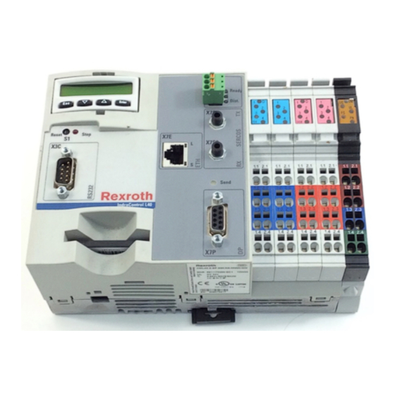
11-1 IndraControl L40 List of Figures List of Figures Fig. 1-1: View of a typical IndraControl L40 unit, with further optional interfaces arranged in the central section. 1-1 Fig. 1-2: Further documentation 1-2 Fig. 3-1: Hazard classification (according to ANSI Z535) 3-1 Fig. - Page 88 11-2 List of Figures IndraControl L40 Fig. 8-2: Latching on a module 8-4 Fig. 8-3: Removing a module 8-5 Fig. 8-4: Fuse replacement 8-6 Fig. 8-5: Setup without electrical isolation 8-8 Fig. 8-6: Setup with electrical isolation 8-9 Fig. 8-7: Reference conductor connected to the protective conductor 8-10 Fig.
- Page 89 11-3 IndraControl L40 List of Figures Fig. 9-26: Light-emitting diode D (see Chapters "Digital Onboard Inputs" and "Digital Outputs" on page 7-8 and following pages) 9-14 Fig. 9-27: Possible indicators on supply terminals (here: segment terminal without and with fuse) 9-15 Fig.
- Page 90 11-4 List of Figures IndraControl L40 DOK-CONTRL-IC*L40*****-PR02-EN-P IAS COMPONENTS www.ias-components.com info@ias-components.com...
-
Page 91: Index
12-1 IndraControl L40 Index Index 2-slot housing 9-8 4-slot housing 9-9 8-slot housing 9-9 Actuators 8-15 Addresses Digital inputs and outputs 7-7 Air pressure 4-2 Ambient conditions 4-2 Analog circuit 7-7 Analog input module IB IL 24 AI 2/SF 8-14 Analog output module IB IL AO ... - Page 92 12-2 Index IndraControl L40 Dimensions of 8-slot housing 9-9 Overall widths 9-1 End plate 8-1 Equipotential bonding 8-13 Ethernet connection 7-12 FE spring 9-12 FE voltage jumper 8-13 Functional earth ground 8-13 Fuse 8-12 Fuse replacement 8-5 Generation of U M 7-4 Generation of U S 7-5...
- Page 93 12-3 IndraControl L40 Index Top-hat rail 8-3 Top-hat Rail 8-1 Voltage and data routing 9-11 Inline station Connection of actuators 8-15 Connection of analog sensors 8-14 Orientation of the shield clip 8-18 Input module IB IL 24 AI 2/SF 8-14 Input/output modules Diagnosis 9-16 Status 9-16...
- Page 94 12-4 Index IndraControl L40 PROFIBUS DP connection 7-13 PROFIBUS line Shielding 8-13 Ready contact 7-14 Relative humidity 4-2 Reset button 6-2 RS232 connection 7-11 Safety Instructions for Electric Drives and Controls 3-1 Segment circuit 7-5, 9-11 Segment voltage 7-5 SERCOS connection 7-14 Shield clip 8-18 Shield connector 8-17, 9-10 Shielded lines 8-17...
-
Page 95: Service & Support
13-1 IndraControl L40 Service & Support Service & Support 13.1 Helpdesk Unser Kundendienst-Helpdesk im Hauptwerk Lohr Our service helpdesk at our headquarters in Lohr am am Main steht Ihnen mit Rat und Tat zur Seite. Main, Germany can assist you in all kinds of inquiries. Sie erreichen uns Contact us +49 (0) 9352 40 50 60... -
Page 96: Kundenbetreuungsstellen - Sales & Service Facilities
Tel.: +49 (0)171 333 88 26 service.svc@boschrexroth.de Vertriebsgebiet Süd Vertriebsgebiet West Gebiet Südwest Germany South Germany West Germany South-West Bosch Rexroth AG Bosch Rexroth AG Bosch Rexroth AG Landshuter Allee 8-10 Regionalzentrum West Service-Regionalzentrum Süd-West 80637 München Borsigstrasse 15 Siemensstr.1... - Page 97 - Italien Netherlands - Niederlande/Holland Netherlands – Niederlande/Holland Bosch Rexroth S.p.A. Bosch Rexroth S.p.A. Bosch Rexroth Services B.V. Bosch Rexroth B.V. Via del Progresso, 16 (Zona Ind.) Via Isonzo, 61 Technical Services Kruisbroeksestraat 1 35020 Padova 40033 Casalecchio di Reno (Bo) Kruisbroeksestraat 1 (P.O.
- Page 98 - Tschechien Czech Republic - Tschechien Hungary - Ungarn Poland – Polen DEL a.s. Bosch -Rexroth, spol.s.r.o. Bosch Rexroth Kft. Bosch Rexroth Sp.zo.o. Strojírenská 38 Hviezdoslavova 5 Angol utca 34 ul. Staszica 1 591 01 Zdar nad Sázavou 627 00 Brno 1149 Budapest 05-800 Pruszków...
- Page 99 Australia - Australien Australia - Australien China China AIMS - Australian Industrial Bosch Rexroth Pty. Ltd. Shanghai Bosch Rexroth Shanghai Bosch Rexroth Machinery Services Pty. Ltd. No. 7, Endeavour Way Hydraulics & Automation Ltd. Hydraulics & Automation Ltd. 28 Westside Drive...
- Page 100 Canada West - Kanada West Mexico Mexico Bosch Rexroth Canada Corporation Bosch Rexroth Canada Corporation Bosch Rexroth Mexico S.A. de C.V. Bosch Rexroth S.A. de C.V. Burlington Division 5345 Goring St. Calle Neptuno 72 Calle Argentina No 3913 3426 Mainway Drive Burnaby, British Columbia Unidad Ind.
- Page 101 IAS COMPONENTS www.ias-components.com info@ias-components.com...
- Page 102 Bosch Rexroth AG Electric Drives and Controls P.O. Box 13 57 97803 Lohr, Germany Bgm.-Dr.-Nebel-Str. 2 97816 Lohr, Germany Phone +49 (0)93 52-40-50 60 +49 (0)93 52-40-49 41 service.svc@boschrexroth.de www.boschrexroth.com Printed in Germany R911308429 DOK-CONTRL-IC*L40*****-PR02-EN-P IAS COMPONENTS www.ias-components.com info@ias-components.com...
Need help?
Do you have a question about the Rexroth IndraControl L40 and is the answer not in the manual?
Questions and answers