Stryker 1000 Maintenance Manual
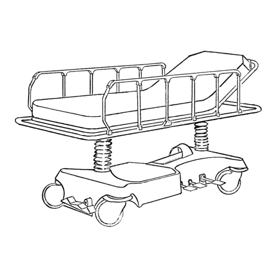
Emergency care stretcher.
pacu stretcher
Hide thumbs
Also See for 1000:
- Operating instructions manual (100 pages) ,
- Pocket manual (2 pages) ,
- Manual (2 pages)


Need help?
Do you have a question about the 1000 and is the answer not in the manual?
Questions and answers