Table of Contents
Advertisement
Dear users:
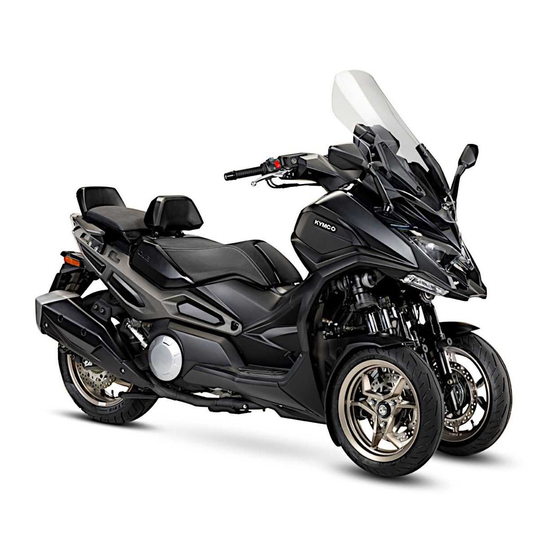
Thank you very much for purchasing our CV3 Series product.
This Manual gives detailed instructions on how to operate, maintain and adjust the CV3 Series for
prolonged durability and comfort. This model of vehicles complies with EPA regulations on scooter
emission control standards, therefore complying environmental requirements in terms of low pollution, low
noise and low energy consumption. Although having exceptional quality, regular maintenance is still
essential for keeping the product in giving optimal performances.
In order to enjoy a safe and comfortable journey with your motorcycle, please read this manual thoroughly.
1
Advertisement
Table of Contents

Related Manuals for KYMCO CV3 Series


Summary of Contents for KYMCO CV3 Series
- Page 1 Thank you very much for purchasing our CV3 Series product. This Manual gives detailed instructions on how to operate, maintain and adjust the CV3 Series for prolonged durability and comfort. This model of vehicles complies with EPA regulations on scooter emission control standards, therefore complying environmental requirements in terms of low pollution, low noise and low energy consumption.
-
Page 2: Table Of Contents
Contents Contents Left Handlebar Switch ..............49 Cruise Control Settings ..............50 Handlebar Heater / Indicator ............52 PRECAUTIONS ON SAFE DRIVING ....4 Rear Brake Lever................55 Front Brake Lever ................56 Parking Brake Arm ................. 56 OWNER INFORMATION ........9 Foot brake .................. - Page 3 Precautions on Safe Driving Parking the Vehicle................. 87 Check Coolant ................117 A tumbled vehicle ................88 INTRODUCTION AND MAINTENANCE TO THE CHECKS BEFORE RIDING ......89 ENVIRONMENTAL MECHANISM ......120 Engine Oil and Oil Filter ..............89 Introduction to the exhaust emission control system ....120 Check/Replenish Engine Oil ............
-
Page 4: Precautions On Safe Driving
Precautions on Safe Driving Hold the Handlebar with both hands when riding. Do Precautions on Safe Driving not ride by single hand for this is extremely dangerous. Wearing flat shoes is safer. Please note! The structure of this vehicle is significantly different from 2-wheel vehicles. - Page 5 Precautions on Safe Driving shall be taken not to touch such surfaces or a burn may occur. Avoid making sharp turns or one-handed driving. Abide by all traffic rules. Smoking is prohibited when replenishing fuel. Stop engine when filling with fuel. ...
- Page 6 Precautions on Safe Driving Do not go near or touch the belt or front/rear wheels while they are in motion to avoid danger. When riding the motorcycle, the rider must place both feet on the pedals; the rear rider shall put arms around the rider’s waist and both feet on the rear ...
- Page 7 Precautions on Safe Driving Avoid dry grasses or flammables when parking the Warning vehicle, for the prevention of fire risks. Do not turn on the ignition and begin its related operations when the vehicle’s main stand has not been erected, especially for children, the elderly, and persons unfamiliar with the characteristics of the vehicle.
- Page 8 Precautions on Safe Driving It is forbidden to install a carrying basket or bracket on The maximum load of the storage box shall be limited to the front header. Carrying anything in front of the vehicle 10kg at most. will surly block the headlight and significantly affect driving safety.
-
Page 9: Owner Information
Engine Number: Please note down the Engine Number and Vehicle Frame Number in the relevant fields below to facilitate ordering spare parts from a KYMCO dealer, or for reference in the event of a lost of vehicle. ID Number Record Field: The Engine Number is engraved on the crank box as shown in the figure. - Page 10 Owner Information Frame Number: Aluminum Nameplate Located on the right side of the front frame. The aluminum nameplate can be seen from the bottom looking up. Frame Number Imprint Engrave the number onto the frame indicated in the drawing. The Frame Number can be seen from Location of the aluminum nameplate lower-right upwards.
- Page 11 Owner Information Mark Drive Caution ① The mark drive caution and label fuel tank of the motorcycle is tagged on the backside of the box,luggage of the scooter (per Fig. 1). ② ① Label Fuel Tank ② (Fig. 1). ③ Stripe Logo KALS ③...
- Page 12 Owner Information Kymco will not disclose this information to a third party Collection of motorcycle data record except for the following conditions: 1. Kymco has acquired the approval of the user and The ECU of this model collects and records the owner of the vehicle.
-
Page 13: Parts Names
Parts Names Parts Names Left View of Scooter 1. Battery 2. Coolant Checking Window 3. Engine Oil Filter 4. Helmet Hook 5. Engine Oil Drain Cock 6. Left Foot Bar 7. Oil level guide 8. Storage Box 9. Left-rear Handlebar... -
Page 14: Right View Of Scooter
Parts Names Right View of Scooter 1. Main Stand 2. Engine Cover 3. Air Filter Element 4. Foot Brake 5. Windshield 6. Dashboard 7. Rear View Mirror 8. Exhaust Pipe Cover 9. Right Foot Bar 10. Backrest... -
Page 15: Dashboard And Control Mechanism
Parts Names Dashboard and Control Mechanism 1. Rear Brake Lever 2. KEYLESS Main switch 3. noodoe Dashboard 4. LOCK switch 5. Parking Brake Arm 6. Seat Compartment 7. Dashboard Selection Switch 8. Right Handlebar Switch 9. Throttle Handle 10. Front brake lever Switch... -
Page 16: Left Handlebar Functions (Front)
Parts Names (rear) Left handlebar functions (front) 1. Power/Rain mode switch 1. Cruise setting key 2. Handlebar heating button 2. High/Low Beam Switch 3. Winker Switch 4. Reset/accelerate button (+) 5. Set/decelerate button (-) 6. Horn Switch 7. Handlebar Heater Indicator... -
Page 17: Right Handlebar Functions (Front)
Parts Names Right handlebar functions (front) (rear) 1. noodoe Pgup / Pgdn Button 1. Release Engine Stop Switch 2. noodoe Enter / Change Button 2. Engine Stop Switch 3. Release Front Wheel Lock 4. Lock Front Wheel 5. Park Alert Switch 6. -
Page 18: Center Multifunction Switches
Parts Names Center Multifunction Switches 1. Dashboard Menu: Switch between main screen and sub-screen selection menu. 2. Storage Box: Storage box switch 3. Odometer Switch: Switch between TRIP A and B 4. Steering Stem Lock: Used to lock the steering stem... -
Page 19: Control Functions Of Mechanism
Control Functions of Mechanism Control Functions of Mechanism LCD Dashboard Function 1. Left winker 2. Fuel gauge 3. High beam 4. Engine oil indicator 5. Engine failure indicator 6. Cruise control 11. Water temperature warning 7. Oil service indicator 8. Settings indicator 9. - Page 20 This denotes a system anomaly; you need to go to a KYMCO dealer for a check-up. Engine inspection indicator: After “KEY ON,” the engine inspection indicator will illuminate and then extinguish by itself after starting the engine.
- Page 21 When the accumulated mileage reaches 20,000 km, KYMCO dealer shop for inspection or repairs the belt change indicator (service symbol) will light up. immediately. The user should take extra care, riding...
- Page 22 If ABS Fault Indicator stays lighting up when vehicle (When TRIP A is reset, the average fuel consumption speed is ≧ 6km/h, it indicates the ABS system is faulty. will also reset.) Please go to a local KYMCO dealer for check-up immediately.
- Page 23 Control Functions of Mechanism 20. Power/Rain mode: The MODE button is located 17. Speedometer: The unit is represented in km/h or mph, among the left handlebar switches, and can be and must be set from the APP. When switching the switched between power/rain modes depending on setting, all units used in the dashboard will be the driver’s need.
- Page 24 Control Functions of Mechanism Mode switch: 21. Tire pressure inspection : When power is receiver When travelling normally, the diagram will read POWER turned on, it will receive the tire pressure status MODE. Press the MODE button on the left handlebar, signals from the front/rear wheels.
- Page 25 Control Functions of Mechanism Anti-tilting lock: The button is located among the right handlebar switches, when the anti-tilting lock is pressed, a white light on the dashboard will stay lit. Press the release button beside it to release the lock, then the white light will flash.
- Page 26 Control Functions of Mechanism LED dashboard – sub-screen Brightness adjustment Press the “MENU” button in the center switch panel to Short-press the up ( ︿ ) button among the right enter the sub-screen selection menu, press again to handlebar switches, select brightness adjustment and return to the main screen.
-
Page 27: Noodoe Function
Control Functions of Mechanism How to enter the noodoe System Enter the noodoe Function Step 1: Download the app. Refer to "Download noodoe Step 1: Download the app. Refer to "Download noodoe app", download the app and the system installs the app app", download the app and the system installs automatically. - Page 28 Control Functions of Mechanism While Driving Step 2: Introduction to operation buttons Operate ( ︿ ) and ( ﹀ ) buttons to switch-over between 4 screens of Dashboard noodoe functions. Press (O) button to end the action. When Stopped: (︿) Button →...
- Page 29 Control Functions of Mechanism Step 3: Scooter Pairing noodoe Function To use Scooter Pairing, the user needs to enter the APP A. Introduction app functions (cell phone) → set up (cell phone) → Scooter Setting → The user may browse and collect creations from users KEY ON (Scooter) →...
- Page 30 Control Functions of Mechanism Create Mode B. Find My Scooter Create Mode allows you to remix an existing template to Forgot where you've parked? No worries, noodoe your liking remembers. Tap the icon and the app will guide Pick between Clock, Weather, Compass or Speed and you back to where you last parked.
- Page 31 Control Functions of Mechanism C. Message Notice D.Welcome Light Once the cell phone is linked, any incoming message When searching for your motorcycle in a congested will be forwarded to the scooter dashboard parking lot or during night hours, open the APP with the ...
- Page 32 Control Functions of Mechanism the power, the “noodoe system” will turn off the 4. The User needs to set the cell phone's Cloud Bluetooth / Online / Welcome function automatically. Messaging function to facilitate noodoe message If the battery is still inactive after starting the engine, display.
- Page 33 11.8V, please start the engine you to execute the setting in the APP). If the or stop using the system and go to a KYMCO dealer standby duration expires or if the battery voltage for checking the circuitry.
-
Page 34: Keyless Car Key
Control Functions of Mechanism Replacing the wireless key battery KEYLESS car key Use appropriate tools for opening The KEYLESS is the hi-tech electronic main switch that does not need a key (per the figure above). Each vehicle Model No. of wireless key battery: CR2032 is equipped with 2 sets of remote controllers and they Caution should be preserved carefully. - Page 35 Control Functions of Mechanism liquids. When the keyless car key battery is low on power, it will affect the sensing distance. Please replace the Do not place heavy objects or apply excessive force battery as soon as possible. onto the keyless car key.
-
Page 36: Keyless Sensing Distance
Control Functions of Mechanism KEYLESS sensing distance shut off, and bring the keyless car key with you. 1. Remote sensing antenna (single open space): The Short-range sensor best sensing distance is within 1.5m; sensing is not If the keyless car key is out of power and is unable to possible past 3.5 m. - Page 37 Control Functions of Mechanism reminder. Press the main switch button again to turn When replacing the battery, avoid inappropriate operations which may damage the functionality of the off. car key. Please visit the professional service station The keyless key car should be carried with you at all for inspection.
-
Page 38: Keyless Main Switch
Control Functions of Mechanism KEYLESS Main Switch power-on scanning screen. The engine can be started once completed. Caution Under engine non-ignition state, when the keyless car key leaves the sensing distance, the system will make a beep sound after 30 sec and turn-off. ... - Page 39 Control Functions of Mechanism KEYLESS controller anti-theft setting – short-range sensor (locking) Place the back of the keyless car key near the right-side circular symbol of the center switch set and press the main switch button. There will be a long beep sound, and this will complete the locking action.
-
Page 40: Steering Stem Lock
Control Functions of Mechanism Steering Stem Lock To further prevent theft, the steering stem should be locked when parking the vehicle. Vehicle locking method: Under the power-off state, turn the steering stem completely to the left, long-press the “LOCK” button for 2 sec, a long beep sound will indicate successful locking. -
Page 41: Main Switch Functions
Control Functions of Mechanism operated through the short-range method. Main Switch Functions The levelness and safety of the parking location There will be 2 beep sounds when opening the main needs to be evaluated when locking and parking the switch, indicating power-on. - Page 42 Control Functions of Mechanism Caution Under any screen state, the screen will return to the main page when the vehicle is powered-off and turned back on. When the unlocking of the steering stem is unsuccessful, please confirm that the steering stem is turned completely to the left, and try unlocking again.
-
Page 43: Right Handlebar Switch
Control Functions of Mechanism oodoe Pgup (︿) / Pgdn (﹀) button Right Handlebar Switch When operating the up (︿)/down (﹀) button, the related noodoe information in the middle of the dashboard will change. noodoe Enter / Change Button Press “O” to enter the selection menu and see the related noodoe information. -
Page 44: Anti-Tilting Lock Switch
Control Functions of Mechanism Anti-tilting Lock Switch 1. When the main switch is turned on, if it is unlocked, 1. When starting the Front Suspension Lock function, it the indicator will flash; the indicator will stay lit when will trigger the Front Suspension Caliper and the Disk locked. - Page 45 Control Functions of Mechanism the 2-wheel vehicle can easily become unstable and of the vehicle. risk tipping over. When riding on muddy, bumpy or coarse road surface When starting the vehicle, it should be set to unlocking conditions. state for a smoother start.
- Page 46 Control Functions of Mechanism Front Suspension in the meantime. the system will release the locking automatically if the 7. If the voltage of the vehicle is low, the Front engine short-time revolution is over 3000rpm. Suspension Lock will execute the unlocking function only.
-
Page 47: Engine Stop Switch
Control Functions of Mechanism Park Alert Switch Engine Stop Switch : Push this switch to the left, all the Park Alert Indicator (4 winkers, left and right, front and rear) will flash. OFF: Push this switch to the right, all the Park Alert Indicator stop flashing. - Page 48 Control Functions of Mechanism Caution Please note! When travelling under high speeds, do not shut off or turn on the engine switch arbitrarily, to avoid dangers of collision or concerns to traffic safety due to loss of speed.
-
Page 49: Left Handlebar Switch
Control Functions of Mechanism Left Handlebar Switch Cruise control setting button: The vehicle speed must be greater than 45km/h to set the setting. The steps are as follows: 1. Press cruise control button ON 2. Start the setting after the indicator is lighted. 3. -
Page 50: Cruise Control Settings
Control Functions of Mechanism Cruise Control Settings Cruise limit adjusting method 1.Setting cruise control a. Under cruise control state a. Press ON to set cruise control b. Press RES (+) for acceleration to cruising speed increases b. When indicator light is lit, begin setup c. - Page 51 Control Functions of Mechanism 3. To prevent from starting the Cruise Control System inadvertently, it should be shut down when not in use. please ensure that the cruise control indicator " " is turned off when not in use. When the previous speed setting is too high for the current riding environment, it will be dangerous to use the resume function.
-
Page 52: Handlebar Heater / Indicator
Control Functions of Mechanism High/Low Beam and Passing Light Switch: Handlebar Heater / Indicator Pushing the switch to “ ” for HIGH, to “ ” for LOW. After turning ON the Main Switch, press and hold Over-pass Light Switch: Handlebar Heater Button for 3s or more to Pressing this button will activate High Beam. - Page 53 For the sake of your safety, please go to a check, in the event of a Handlebar Heater anomaly, KYMCO dealer for check-up. the indicator will flash in red, with the Handlebar Heater function disabled. (Refer to anomaly states...
- Page 54 Control Functions of Mechanism (This is only the setting value; the actual temperature depends on the environment temperature and vehicle condition, a difference may exist.) c. If the signal from the controller to the dashboard is faulty for any cause, a symbol flashes in the Dashboard.
-
Page 55: Rear Brake Lever
Control Functions of Mechanism Rear Brake Lever Rear Brake Lever situates on the Left Handlebar; when applying the Rear Brake, hold the Front Brake Lever Caution with left hand and apply a proper force on it. The rear brake handlebar is equipped with a position adjusting knob. -
Page 56: Front Brake Lever
Control Functions of Mechanism Front Brake Lever Parking Brake Arm Front Brake Lever situates on the Right Handlebar; when applying the Front Brake, hold the Front Brake Lever with right hand and apply a proper force on it. Warning Parking Brake Arm Improper operation may result in danger. - Page 57 Control Functions of Mechanism Warning Never use the Parking Brake Arm while riding the vehicle, or loss of control of the vehicle and an accident may occur. Make sure the vehicle is fully stopped before using this Parking Brake Arm. When using the Parking Brake Arm, verify if rear tire ...
-
Page 58: Foot Brake
Control Functions of Mechanism Foot brake Helmet Hook Helmet Hook Foot brake pedal This vehicle is equipped with the foot brake function as A Helmet Hook is provided on the front edge of Seat an auxiliary to the front/rear braking system. Thus, the Pad. -
Page 59: Storage Box
Control Functions of Mechanism The Storage Box is located under the seat cushion Storage Box and it can be used to store the safety hat and other 1.Electronic objects. When the KEYLESS main switch is at KEY ON, ... - Page 60 Control Functions of Mechanism 2. Mechanical: When the vehicle is out of power or if one does not Warning have the KEYLESS car key, it will require a physical Store the safety hat with the most appropriate key to open the storage box. method.
- Page 61 Control Functions of Mechanism Empty the Storage Box before washing the vehicle, so that objects do not get wet. Due to engine operation and environmental factors, the Storage Box tends to be warm and humid; do not put fragile, flammable or easy to decay objects in it. ...
-
Page 62: Windshield
Control Functions of Mechanism Components inside the Storage Box Windshield LED: There are two options of Windshield Height subjecting to The lamp lights up when Seat Pad is lifted up, goes out rider’s need. when closed. (After closing the seat pad, confirm that the “... - Page 63 Control Functions of Mechanism Adjusting Windshield Height 3. Remove the Windshield spacer holder. 1. Remove the screw and then remove the front Windshield protection cover. 1: Windshield spacer holder 4. Install the Windshield spacer holder at the most appropriate position. Tighten screws to specified 1: Front windshield protection cover torque.
-
Page 64: Rear View Mirror
Control Functions of Mechanism Rear View Mirror 7. Restore the front windshield protection cover and then install the screw. Rear View Mirrors are the important equipment for securing the rider's safety before and during riding. Proper use of the Rear View Mirror is essential. Rear View Mirror is designed to be capable of turning forward and backward. -
Page 65: 12V Power Socket
Control Functions of Mechanism 12V Power Socket Power Socket. Warning 12V Power Socket can only be used with a running engine. To prevent power depletion of battery, do not charge a product using the 12V Power Socket without running the engine. -
Page 66: Rider Backrest
Control Functions of Mechanism Rider Backrest Rear Seat The CV3 adopts the split-type seat design, where the rear seat padding can be switched between solo rider and 2- person rider mode. Solo rider mode switch 1. Open the Storage Box 2. - Page 67 Control Functions of Mechanism key hole trim Warning Ensure that the locking latch firmly locks onto the seat when the seat pad is replaced, to prevent dangers of the seat falling while riding. If the locking latch is loose or faulty, please visit the dealer shop for repairs.
-
Page 68: Main Stand
Main Stand may fail to spring up to position while running the vehicle if the bracket spring becomes weak. Go to a KYMCO service station for replacement as soon as possible. 1: Main Stand Caution... -
Page 69: Fuel Filler Cap
Control Functions of Mechanism Fuel Filler Cap Open Locked Open the fuel filler cap by lifting upwards, then twist to the left to open the cap. The fuel filler cap can be seen after opening the seat pad. Close the outer cover of the Gasoline Tank and then screw back the Gasoline Tank cover. -
Page 70: Tpms, Electronic Tire Pressure Sensor
5. Re-adjustment of TPMS is required when replacing a new wireless tire pressure sensor and controller; please consult a KYMCO dealer. 6. When replacing a tire rim, the Tire Pressure Sensor shall be kept in a correct order to distinguish the front one and the rear one. - Page 71 Control Functions of Mechanism TPMS Learn Code Operation: Applicable to owner and dealer service personnel. Re-adjustment of TPMS is required when replacing a new wireless tire pressure sensor and controller. When performing code learning, keep the vicinity clear of other vehicle or transmitter, to prevent miss- triggering.
- Page 72 Control Functions of Mechanism learning. 6. Slackening of nut during parts installation will cause 8. The operator will also go the next tire and repeat the air leakage. above steps for code-learning settings. 7. If the tire pressure cannot be detected, it means the 9.
- Page 73 Control Functions of Mechanism Change Pressure Unit With KEYLESS main switch ON, open the APP and Bluetooth and connect with the vehicle. When connected, select “Setting” -> “Preference Setting” -> the display unit for tire pressure can be changed according to the owner’s preference.
- Page 74 Control Functions of Mechanism TPMS abnormal status: Depending on the TPMS error state, the dashboard will display with the indicator light and the message bar as well as the tire pressure screen. The messages are as follows. Meter indicator Meter icon display Displayed priority Abnormal status Remarks...
-
Page 75: Abs (Anti-Lock Braking System)
Control Functions of Mechanism ABS (Anti-lock Braking System) automatically. The ABS Brake Indicator only goes off when engine is started and vehicle runs above 6km/hr. Caution ABS is controlled by ECU; if ABS fails, the ABS Brake Indicator will light up; ABS may lose its function, but the original brake still works;... - Page 76 System. Therefore it is a must that you use tires skidding. conforming to KYMCO specifications. An ABS system will not shorten braking distance in When ABS activates, you may feel a light vibration the following conditions: when running on a soft and on the Brake Lever, which is a normal phenomenon.
-
Page 77: O2 Sensor
Control Functions of Mechanism O2 Sensor Muffler and Catalytic Converter Muffler O2 Sensor This vehicle is provided with O2 Sensor for reducing Catalytic Converter is used for reducing generation of generation of pollutants in the exhaust gas. pollutants in the exhaust gas. Warning Do not dismantle or replace O2 Sensor by yourself, otherwise the O2 Sensor may deteriorate or lose... -
Page 78: Exhaust Control System
Control Functions of Mechanism Warning To prevent fire or burn: Exhaust Control System Park the vehicle properly so that pedestrian or children Complying with EPA Exhaust Emission Standard, the cannot reach. scooter is equipped with following parts in the Exhaust ... -
Page 79: Proper Riding Method
Proper Riding Method Proper Riding Method this position. Starting the Engine Caution 1. Lift up Main Stand before starting the engine. 3. The Main Power is cut off when the Engine Stop Switch 2. Check oil and gasoline content before starting the engine. is set to the position, therefore pulling the Brake Lever and pushing the Start Button will not activate the... - Page 80 Proper Riding Method try shall not exceed 5 seconds, for preserving battery power. Caution Caution When not in use after stopping the vehicle, be sure to Keep finger off from Start Button immediately when set the main switch key to the “OFF” position to prevent engine starts.
-
Page 81: Proper Riding Method
Proper Riding Method Proper Riding Method Keep the Rear Brake Lever in braking state and push the vehicle forward, the Main Stand will spring up automatically. Mount the vehicle from the left side and then sit squarely, with both feet touching the ground to prevent tilting. - Page 82 Proper Riding Method Release Front and Rear Brake Levers Turn the Throttle Grip to adjust scooter speed. Speed is controlled by adjusting the Throttle Grip. Warning The more the turning range, the quicker the vehicle After releasing the brake, do not turn the Throttle Grip speed.
- Page 83 Proper Riding Method Do not turn the Throttle Grip rapidly, or the vehicle may dash out. When the vehicle is starting under the 3-wheel state, the vehicle will automatically unlock as the speed exceeds the unlocking threshold and become the 2- wheel state;...
-
Page 84: Brakes
Proper Riding Method Proper Riding Before taking off, switch on the winker, check traffic Brakes conditions both directions, slowly turn the Throttle Grip to Front Brake start. Rear Brake Running-in a new engine Run-in Period of a new engine is 300km; keep speed under 80 km/h in this period. - Page 85 Proper Riding Method Foot brake effective braking distance and is more difficult. Slow down while running on mountain roads; it will be more difficult to brake while running down-slope, more dangerous as well. Do not brake or turn abruptly. ...
-
Page 86: Proper Parking Method
Proper Riding Method Proper Parking Method When approaching to a parking location: Switch on the winker in advance and take heed of vehicles behind you while slowly pulling-over. Restore the refueling handle to its original position and then use the front, rear and pedal brakes at an earlier stage. -
Page 87: At Full Stop Of Vehicle
If the KEYLESS Main Switch can be turned off during the crusing process, it means the fail-safe function has failed. Parking the Vehicle Go to a KYMCO dealer or service station for repair as Standing on the left side on a flat ground, the rider shall quickly as possible. -
Page 88: A Tumbled Vehicle
Proper Riding Method A tumbled vehicle vehicle. Lift it, make sure the surroundings are safe, To restart a tumbled vehicle with engine stopped, you and move the vehicle to a safe location. need to turn the KEYLESS Main Switch off and on again ... -
Page 89: Checks Before Riding
Checks before Riding in an enclosed space; there is a risk of carbon Checks before Riding monoxide intoxication due to exhaust emission. Keep a good habit to perform checks before riding To avoid damaging the vehicle, never carry out any For keeping your vehicle in a safe and effective operating maintenance without receiving a professional training condition, perform regular checks, adjustments and... -
Page 90: Check/Replenish Engine Oil
Checks before Riding Check/Replenish Engine Oil 1. Park the vehicle on flat ground and brace up the Main Caution Stand. Activate KEYLESS Main Switch and start the Engine and Muffler are extremely hot. Take special engine, idle it for about 3 minutes without using care to prevent burn while checking oil level. -
Page 91: Check/Replenish The Fuel
When replenishing the fuel, keep the fuel level below possible. the baseline plate, otherwise the fuel will overflow. It is recommended to add "Kymco Nozzle Cleaner" in Using Fuel Tank Cap the fuel every 10,000km when replenishing the fuel, Stop Engine first for cleaning Fuel Injection Nozzle. -
Page 92: Check Steering Stem
5. When finding any anomaly, go to a KYMCO of Brake Lever is within the specified dimension. dealer or service station for repair. -
Page 93: Inspection Of Front/Rear Brake Oil
Checks before Riding Inspection of front/rear brake oil Front / rear brake oil replenishing 1. Set the handlebar squarely and then check the 1. Straighten the Handlebar, remove 2 fixing screws of brake oil in the left and right fuel tank. Keep the level Reservoir and remove Reservoir Cover. -
Page 94: Check Front/Rear Brake Lining
When the tire pressure is very low or the tires are Check the brake lining, when the wear limit is reached, incorrectly balanced, riding of the vehicle will lead to please contact the KYMCO dealer shop for replacement. dangerous rotational vibrations. - Page 95 In case of finding a transverse line (minimum pattern depth), nail or glass chip on the tire, or crack line on the side wall of tire, go to Kymco dealer for replacing with new one. Excessive wear of tire tread pattern will result in reduce friction and the tire will become more prone to be punctured;...
-
Page 96: Check The Brake Light
Checks before Riding Check the Brake Light Check the Tail Light Turn on the KEYLESS main switch power. Turn on the KEYLESS main switch power. Respectively pull the Front and Rear Brake Levers, verify Check if the Tail Light goes on. if Brake Light goes on. -
Page 97: Check The Headlight
Checks before Riding Check the Headlight Turn on the KEYLESS main switch power. Turn on ignition of the engine. Check if the Headlight goes on. Check the Headlight Lens for stain or fracture. Headlight... -
Page 98: Check Winkers
Checks before Riding Check Winkers Rear Winker Turn on the KEYLESS main switch power. Operate Winker Switch to verify if each Winker works. Check Winker lens for stain or fracture. Front Winker Rear Winker... -
Page 99: Check Front/Rear Cushion
Checks before Riding Check Front/Rear Cushion Check Dashboard for normal display. Hold the front brake. Press the handlebar hard several Check the Horn for working normally. times and then check if the front fork is operating and Set the KEYLESS Main Switch in the “START” position bouncing smoothly. -
Page 100: Inspect The Outer Transmission Belt
Caution Please do not adjust the belt and remove relevant rear wheel mechanisms arbitrarily. They should be repaired by professionals at the KYMCO service station. If there are cracks or deformed damages to the top/bottom covers, they should be repaired immediately for safety. -
Page 101: Simplified Maintenance And Repair
To ensure comfortable riding, regularly checking of your Take safety precautions while performing maintenance. vehicle is necessary. Please go to a KYMCO dealer or Brace the vehicle with its main stand on a level service station for after sales service and maintenance. - Page 102 CVT clutch outer should be cleaned to remove any dirt or Ignition Circuit and ECU foreign object inside during regular maintenance. We recommend that you add a bottle of Kymco fuel injector Throttle Body Fuel Injector Diagnostic Tool...
-
Page 103: Check Battery
Simplified Maintenance and Repair Check Battery This vehicle uses maintenance-free battery. Detach the rear seat pad, and remove the rubber cover No battery fluid replenishment is required. of the rear seat pad Check battery voltage: Remove a total of 6 screws, and detach the seat pad cover Battery voltage shall exceed 12V when checked using a voltmeter. - Page 104 Simplified Maintenance and Repair Disassembly of the battery cover 2. Remove the positive/negative pole screws from the 1. Remove 3 screws to detach the battery cover. battery. 3. Remove Battery...
- Page 105 A weakened battery voltage is displayed on the Dashboard; you will need to remove the battery and fully re-charge it, or go to a KYMCO service station for service. If battery is stored for more than 2 months, it shall be checked monthly and re-charged if necessary.
- Page 106 Fully tight a slackened nut of battery poles. KYMCO dealer for re-charge. Keep in mind that the more option devices installed on the vehicle, the faster the battery power depletes.
- Page 107 Simplified Maintenance and Repair Fuse Replacement The fuse is located to the left of the battery. Open the fuse cover to get to the fuse. Turn KEYLESS Main Switch off, check for blown Fuse. Only replace with a fuse of specified capacity. ...
- Page 108 Simplified Maintenance and Repair Remove the backup fuse cover. Backup fuse When replacing the fuse, the spare fuse should be Flip to its back to obtain the backup fuse. placed on the top side of the battery protective cover. Remove the 2 screws from the top side of the cover.
- Page 109 Simplified Maintenance and Repair Backup fuse specifications and configuration Caution Only replace electrical devices (lights, meters) with ones of specified ratings. If using an inadequate fuse, it may be blown easily or battery loading may become imbalance. Avoid frontal strong water jet when cleaning the vehicle.
-
Page 110: Air Filter
Simplified Maintenance and Repair Air Filter Replace Air Filter Element as specified in Regular Maintenance Schedule. Check and replace Air Filter Element more frequently if vehicle is often used in dusty environments or damp areas. Replace Air Filter Element 1. Remove outer covers of vehicle. 2. -
Page 111: Cvt Transmission System Filter Wool
Simplified Maintenance and Repair CVT Transmission System Filter Wool Cleaning Method Excessive dust accumulation in CVT Transmission 1. Remove side plate on the right. System may result in unsmooth vehicle operation; clean 2. Remove Fixing Bolts of Crankcase Right Cover. and replace Filter Wool regularly. - Page 112 Dashboard and light cover, please consult a as to prevent any potential danger. KYMCO dealer for receiving service. 4. When the user or personnel of service station removes the muffler, it is necessary to disconnect...
-
Page 113: Change Oil
Dismantle: 3.0L (full capacity) Change oil: 2.6L (excluding oil filter) 2.7L (including oil filter) Caution To avoid using poor quality oil, please go to a KYMCO dealer for oil change. Oil Change Period 1. Remove Oil Level Guide. Remove Drain Bolt. - Page 114 Simplified Maintenance and Repair shall be 2.6L each time (if the engine oil filter is Caution included, then the replenishing volume shall be It is recommended to use KYMCO original 4-stroke 2.7L). engine oil. 4. Fully tighten the Oil Level Guide.
- Page 115 Do not mix-use oils of different brand, class or low quality ones; they may cause engine faults. Kymco Emissary Engine Oil contains additives (e.g. spirits, etc.) during the manufacturing process. Arbitrarily mixing additives bought from the market may deteriorate the oil, affect lubricating properties and shorten the service life of engine.
-
Page 116: Spark Plug Check And Adjustment
Simplified Maintenance and Repair Spark Plug Check and Adjustment Specified Spark Plug: Dirty electrode or excessive gap can cause poor sparking. (NGK) CR7E Cleaning Method Use a Spark Plug Cleaning Device is the best way If a Spark Plug Cleaning Device is not available, clean with a needle brush. -
Page 117: Check Coolant
Simplified Maintenance and Repair Check Coolant For the sake of safety, check level of coolant before riding the vehicle. Replace the coolant as specified in Regular Maintenance Schedule. Check Level of Coolant 1. Park the vehicle on flat ground and brace it up with Main Stand. - Page 118 Using poor quality coolant may shorten the service life of radiator. Please be careful. Go to a KYMCO Dealer for check and repair. Replace coolant in the radiator every 10000km. Add proper amount of radiator additives to ensure performance of the cooling system.
- Page 119 Simplified Maintenance and Repair In case of fault of vehicle: Go to a KYMCO dealer for check and repair if any fault occurs when riding the vehicle. Use only original parts for replacement. Check following items if engine does not start or engine stops when riding the vehicle: Whether gasoline is sufficient.
-
Page 120: Introduction And Maintenance To The Environmental Mechanism
Introduction and maintenance to the environmental mechanism Introduction and maintenance to the Warning environmental mechanism The exhaust pipe is extremely hot. The vehicle must be parked in places where passersby and children cannot Introduction to the exhaust emission control system touch arbitrarily. - Page 121 Introduction and maintenance to the environmental mechanism Maintenance for the exhaust emissions control system Introduction to evaporative emission control system Method of operation: (E.E.C) The E.E.C device is used to collect the evaporated oil 1. For replacement of the filter for the air filter, please and gas from the gas tank and the throttle valve, to refer to method of operation for “air filter”.
- Page 122 Introduction and maintenance to the environmental mechanism Keyless Noodoe TPMS Manufuctuer Fames Technology Co., Ltd Kwang Yang Motor Co., Ltd Lihjoen Speed Meter Co., Ltd report report report Receiver 2ABPM-S300068900T 2AMA5-LJ-39600 Control 2ABPM-S100334400T 021-170813 Receiver: MSIP-CRM-LIJ-39660-LGC6-00 Control: MSIP-REM-LIJ-39650-LGC6-E00 Receiver: CCAN21LP0680T6 CCAN17LP0260T0 Receiver: CCAL17LP0150T9...
-
Page 123: Specifications
Specifications Specifications CV3 - SBA1CA Item Specifications Item Specifications Engine Type SBA1 Total Length 2140 mm Displacement 550.4 c.c. Total Width 785 mm Cylinder diameter × Stroke 69*73.6 Total Height 1450 mm Compression Ratio Axle Base 1580 mm Gear Shifting Method Front wheel axle base 465 mm 110/70-13... - Page 124 CV3 Series Operation Instructions – KWANG YANG MOTOR CO., LTD. First Edition - 2022 July Copyright © Do Not Copy...
Need help?
Do you have a question about the CV3 Series and is the answer not in the manual?
Questions and answers