
Related Manuals for CAME ZF1N110


Summary of Contents for CAME ZF1N110
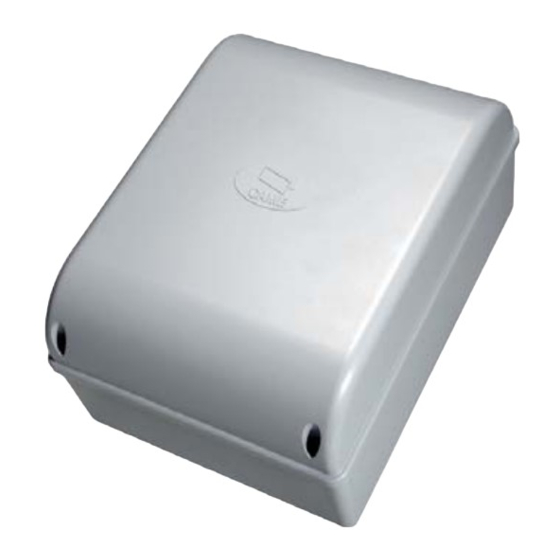
- Page 1 QUADRO COMANDO FA00679M04 PER MOTORIDUTTORI A 120 V O 230 V IT Italiano EN English ZF1N110 / ZF1N FR Français RU Pусский MANUALE DI INSTALLAZIONE...
-
Page 2: Dati Tecnici
Tutte le connessioni e i collegamenti sono protetti da fusibili rapidi. Destinazione d'uso Il quadro comando ZF1N110 / ZF1N è stato progettato per il comando dei motoriduttori CAME per cancelli a battente a uso residenziale o condominiale. Ogni installazione e uso diff ormi da quanto indicato nel seguente manuale sono da considerarsi vietate. -
Page 3: Descrizione Delle Parti
Descrizione delle parti ① Trasformatore ② Fusibile di linea ③ Morsettiera per alimentazione ④ Morsettiere per trasformatore ⑤ Fusibile scheda ⑥ Morsettiera per dispositivi di comando e sicurezza ⑦ LED di segnalazione ⑧ Morsettiera per antenna ⑨ DIP ⑩ Connettore per scheda AF ⑪ ... - Page 4 Attrezzi e materiali Assicurarsi di avere tutti gli strumenti e il materiale necessario per eff ettuare l’installazione nella massima sicurezza e secondo le normative vigenti. In fi gura alcuni esempi di attrezzatura per l’installatore. Tipo di cavi e spessori minimi lunghezza cavo Collegamento <...
-
Page 5: Installazione
INSTALLAZIONE Fissaggio del quadro comando Fissare la base del quadro in una zona protetta con viti e tasselli . Si consiglia di usare viti con testa cilindrica (6 x 70 mm). Forare sui fori presfondati (18 e 20 mm) sotto la base del quadro . ⚠ ... - Page 6 Collegamento dei motoriduttori Motoriduttore (M1) 120 V AC* o 230 V AC, Motoriduttore (M2) 120 V AC* o 230 V AC, ritardato in apertura. ritardato in chiusura. FERNI FERNI FAST FAST KRONO KRONO * versione 120 V AC se disponibile U V W X Y E Limitatore di coppia motore Per variare la coppia motore, spostare il faston indicato su una delle 4 posizioni: 1 min - 4 max.
- Page 7 Dispositivi di comando TS 5 C1 7 2 1 11 10 ES ES Pulsante di STOP (contatto NC). Permette l’arresto del cancello con l’esclusione della chiusura automatica. riprendere movimento premere il pulsante di comando o un altro dispositivo di comando. Se non utilizzato, cortocircuitare il contatto.
- Page 8 Dispositivi di sicurezza Fotocellule Ingresso per dispositivi di sicurezza tipo fotocellule. Riapertura durante la chiusura. In fase di chiusura del cancello, l’apertura del contatto provoca l’inversione del movimento fi no alla completa apertura; Se non vengono utilizzate le fotocellule, cortocircuitare il contatto 2-C1. TS 5 C1 7 2 1 11 10 ES ES TS 5 C1 7 2 1 11 10 ES ES - NO C...
- Page 9 FUNZIONI E REGOLAZIONI Funzioni Descrizione delle funzioni CHIUSURA AUTOMATICA Chiusura automatica attiva (1 OFF - Disattivata) APRE-STOP-CHIUDE-STOP Funzione APRE-STOP-CHIUDE-STOP (sequenziale) da dispositivo di comando (contatto NO) e da trasmettitore radio con scheda AF. APRE-CHIUDE-INVERSIONE Funzione APRE-CHIUDE-INVERSIONE (passo-passo) da dispositivo di comando (contatto NO) e da trasmettitore radio con scheda AF.
-
Page 10: Operazioni Preliminari
GESTIONE UTENTI CON COMANDO RADIO Operazioni preliminari Collegare il cavo RG58 dell’antenna agli appositi morsetti . Inserire la scheda AF sul connettore della scheda elettronica . Prima di inserire la scheda AF, è OBBLIGATORIO TOGLIERE LA TENSIONE DI LINEA e, se presenti, scollegare le batterie. - Page 11 Cancellazione di un singolo utente Posizionare il DIP 4 in ON. Tenere premuto il tasto PROG sulla scheda elettronica. Il LED di programmazione lampeggia . Entro 5 secondi, premere il tasto del trasmettitore dell'utente da cancellare. Il LED lampeggia velocemente per un secondo a segnalare l’avvenuta cancellazione dopodichè...
-
Page 12: Operazioni Finali
Vanno quindi rimossi e consegnati a ditte autorizzate al recupero e allo smaltimento degli stessi. NON DISPERDERE NELL’AMBIENTE! RIFERIMENTI NORMATIVI CAME SPA dichiara che il prodotto è conforme alle direttive di riferimento vigenti al momento della produzione dello stesso. CAME S.p.A. - Page 13 CONTROL PANEL FA00679-EN FOR 120 V OR 230 V GEARMOTORS ZF1N110 / ZF1N EN English INSTALLATION MANUAL...
-
Page 14: Intended Use
All connections and links are rapid-fuse protected. Intended use The ZF1N110 / ZF1N control panel is designed to control CAME gearmotors for swing gates in private homes and apartment buildings. Any installation and/or use other than that specifi ed in this manual is forbidden. -
Page 15: Description Of Parts
Description of parts ① Transformer ② Line fuse ③ Power supply terminals ④ Transformer terminal boards ⑤ Control-board fuse ⑥ Terminals for control and safety devices ⑦ Alert LED ⑧ Antenna terminal ⑨ DIP-SWITCH ⑩ AF card connector ⑪ Automatic closing trimmer ⑫ ... -
Page 16: Tools And Materials
Tools and materials Make sure you have all the tools and materials you will need for installing in total safety and in compliance with applicable regulations. The fi gure shows some of the equipment installers will need. Cable types and minimum thicknesses cable length Connection <... -
Page 17: Installation
INSTALLATION Fastening the control panel Fasten the control panel in a protected area using suitable screws and dowels . Only use 6 x 70 mm cylinder-head screws. Drill through the pre-drilled holes (18 and 20 mm) under the control panel's base . ⚠ ... - Page 18 Connecting the gearmotors Gearmotor (M1) 120 V AC* or 230 V AC, Gearmotor (M2) 120 V AC* or 230 V AC, delayed when opening. delayed when closing. FERNI FERNI FAST FAST KRONO KRONO * 120 V AC version if available U V W X Y E Motor's torque limiter To vary the motor torque, move the faston as shown to one of the four positions: 1 min ÷...
- Page 19 Command and control devices TS 5 C1 7 2 1 11 10 ES ES STOP button (NC contact). For stopping the gate while excluding automatic closing. To resume movement press the control button or use another control device. If unused, short-circuit the contact. OPEN-CLOSE-INVERT function (step-step) from control device (NO contact).
- Page 20 Safety devices Photocells Input for safety devices such as photocells. Reopening during closing. When the gate is closing, opening the contact triggers the inversion of movement until the gate is fully open again; If the photocells are left unused, short-circuit contact 2-C1. TS 5 C1 7 2 1 11 10 ES ES TS 5 C1 7 2 1 11 10 ES ES - NO C...
-
Page 21: Functions And Settings
FUNCTIONS AND SETTINGS Functions DIP-SWITCH Description of functions AUTOMATIC CLOSING Automatic closing active (1 OFF - Deactivated) OPEN-STOP-CLOSE-STOP OPEN-STOP-CLOSE-STOP (sequential) function from control device (NO contact) and from radio transmitter fitted with AF card. OPEN-CLOSE-INVERT OPEN-CLOSE-INVERT (step-step) function from control device (NO contact) and from radio transmitter fitted with AF card. -
Page 22: Preliminary Operations
MANAGING USERS BY RADIO CONTROL Preliminary operations Connect the RG58 cable antenna cable to the corresponding terminals . Fit the AF card into the control board connector . Before fi tting the AF card, you MUST CUT OFF THE MAIN POWER SUPPLY and, remove any emergency bat- teries. -
Page 23: Deleting A Single User
Deleting a single user Set DIP-switch 4 to ON. Keep pressed the PROG button on the control board. The programming LED fl ashes. Within fi ve seconds, press the button on the transmitter of the user you wish to delete. The LED will fl ash quickly for one second to signal that the user has been deleted, and then it will switch off . -
Page 24: Final Operations
These must therefore be disposed of by authorized, certifi ed professional services. DISPOSE OF RESPONSIBLY! REFERENCE REGULATIONS CAME SpA declares that this product complies with the current directives at the time it is manufactured. CAME S.p.A. Via Martiri Della Libertà, 15 31030 Dosson di Casier - Treviso - Italy tel. - Page 25 ARMOIRE DE COMMANDE FA00679-FR POUR MOTORÉDUCTEURS EN 120 V OU 230 V ZF1N110 / ZF1N FR Français MANUEL D'INSTALLATION...
-
Page 26: Utilisation Prévue
Toutes les connexions sont protégées par des fusibles rapides. Utilisation prévue L’armoire de commande ZF1N110 / ZF1N a été conçue pour la commande des motoréducteurs CAME pour portails battants à usage résidentiel ou collectif. Toute installation et toute utilisation autres que celles qui sont indiquées dans ce manuel sont interdites. -
Page 27: Description Des Parties
Description des parties ① Transformateur ② Fusible de ligne ③ Bornier d'alimentation ④ Borniers pour transformateur ⑤ Fusible carte ⑥ Bornier pour dispositifs de commande et de sécurité ⑦ Voyant de signalisation led ⑧ Bornier pour antenne ⑨ Micro-interrupteurs DIP ⑩ ... -
Page 28: Outils Et Matériel
Outils et matériel S'assurer de disposer de tous les instruments et de tout le matériel nécessaire pour eff ectuer l'installation en toute sécurité et conformément aux normes en vigueur. La fi gure illustre quelques exemples d'outils utiles à l'installateur. Types de câbles et épaisseurs minimum longueur câble Connexion <... -
Page 29: Branchements Électriques
INSTALLATION Fixation de l'armoire de commande Fixer la base de l’armoire dans une zone protégée à l'aide de vis et de chevilles . Il est conseillé d'utiliser des vis à tête cylindrique (6 x 70 mm). Percer les trous préforés (18 et 20 mm) sous la base de l'armoire . ⚠ ... - Page 30 Connexion des motoréducteurs Motoréducteur (M1) 120 VAC* ou 230 VAC, Motoréducteur (M2) 120 VAC* ou 230 VAC, retardé à l’ouverture. retardé à la fermeture. FERNI FERNI FAST FAST KRONO KRONO * version 120 VAC si disponible U V W X Y E Limiteur de couple moteur Pour varier le couple moteur, déplacer la cosse indiquée sur une des 4 positions : 1 min.
- Page 31 Dispositifs de commande TS 5 C1 7 2 1 11 10 ES ES Bouton d'ARRÊT (contact NF). Permet l'arrêt du portail avec désactivation de la fermeture automatique. Pour reprendre le mouvement, appuyer sur le bouton de commande ou sur un autre dispositif de commande.
- Page 32 Dispositifs de sécurité Photocellules Entrée pour dispositifs de sécurité type photocellules. Réouverture durant la fermeture. Durant la phase de fermeture du portail, l'ouverture du contact provoque l'inversion du mouvement jusqu'à ouverture totale du portail ; Si les photocellules ne sont pas utilisées, court-circuiter le contact 2-C1. TS 5 C1 7 2 1 11 10 ES ES TS 5 C1 7 2 1 11 10 ES ES - NO C...
-
Page 33: Fonctions Et Réglages
FONCTIONS ET RÉGLAGES Fonctions Description des fonctions FERMETURE AUTOMATIQUE Fermeture automatique activée (1 OFF - Désactivée) OUVERTURE-ARRÊT-FERMETURE-ARRÊT Fonction OUVERTURE-ARRÊT-FERMETURE-ARRÊT (séquentielle) depuis un dispositif de commande (contact NO) et un émetteur radio avec carte AF. OUVERTURE-FERMETURE-INVERSION Fonction OUVERTURE-FERMETURE-INVERSION (pas-à-pas) depuis un dispositif de commande (contact NO) et un émetteur radio avec carte AF. -
Page 34: Opérations Préliminaires
GESTION DES UTILISATEURS PAR COMMANDE RADIO Opérations préliminaires Connecter le câble RG58 de l’antenne aux bornes spécifi ques . Insérer la carte AF sur le connecteur de la carte électronique . Avant d'installer la carte AF, il est OBLIGATOIRE DE METTRE HORS TENSION et de déconnecter les éventuelles batteries. - Page 35 Élimination d'un seul utilisateur Positionner le micro-interrupteur (DIP) 4 sur ON. Maintenir enfoncée la touche PROG sur la carte électronique. Le voyant de programmation led clignote . Appuyer, dans les 5 secondes qui suivent, sur la touche de l'émetteur de l’utilisateur à éliminer. Le voyant clignote rapidement pendant une seconde pour signaler l’élimination eff ective puis s’éteint .
-
Page 36: Opérations Finales
Il faut donc les désinstaller et les remettre aux entreprises autorisées à les récupérer et à les éliminer. NE PAS JETER DANS LA NATURE ! RÉFÉRENCES NORMATIVES CAME SPA déclare que ce produit est conforme aux directives de référence en vigueur au moment de sa production. CAME S.p.A. - Page 37 БЛОК УПРАВЛЕНИЯ FA00679-RU ЭЛЕКТРОПРИВОДАМИ ~120 В ИЛИ ~230 В ZF1N110 / ZF1N RU Русский ИНСТРУКЦИЯ ПО МОНТАЖУ...
-
Page 38: Условные Обозначения
используются DIP-переключатели и регулировки. Все подключения защищены плавкими предохранителями. Назначение Блок управления ZF1N110 / ZF1N разработан для управления приводами САМЕ для распашных ворот, установленных в частных жилых домах и жилых комплексах. Запрещается использовать устройство не по назначению и устанавливать его методами, отличными... -
Page 39: Основные Компоненты
Основные компоненты ① Трансформатор ② Входной предохранитель ③ Контакты электропитания ④ Контакты подключения трансформатора ⑤ Предохранитель платы ⑥ Контакты подключения устройств управления и безопасности ⑦ Светодиодный индикатор ⑧ Контакты подключения антенны ⑨ DIP-переключатели ⑩ Разъем для платы радиоприемника AF ⑪ Регулировка времени... - Page 40 Инструменты и материалы Перед началом монтажных работ убедитесь в наличии всех необходимых инструментов и материалов, которые позволят произвести установку системы в полном соответствии с действующими нормами безопасности. На рисунке представлен минимальный набор инструментов, необходимых для проведения монтажных работ. Тип и сечение кабелей Длина...
-
Page 41: Электрические Подключения
УСТАНОВКА Монтаж блока управления Закрепите основание блока управления в защищенном от механических повреждений месте с помощью винтов и дюбелей .. Рекомендуется использовать винты с цилиндрической головкой (6 x 70 мм). Рассверлите отверстия в предварительно размеченных местах (18 и 20 мм) под основанием блока управления... - Page 42 Подключение приводов Привод (M1) ~120 В * или ~230 В, замед- Привод (M2) ~120 В * или ~230 В, замед- ленное открывание. ленное закрывание. FERNI FERNI FAST FAST KRONO KRONO * версия ~120 В, при наличии U V W X Y E Регулировка...
- Page 43 Устройства управления Кнопка «СТОП» (нормально-замкнутые кон- такты). Данная кнопка позволяет остановить движение ворот с последующим исключе- TS 5 C1 7 2 1 11 10 ES ES нием цикла автоматического закрывания. Для возобновления движения створки не- обходимо нажать соответствующую кноп- ку управления или пульта дистанционного управления.
- Page 44 Устройства безопасности Фотоэлементы Контакты подключения устройств безопасности, например, фотоэлементов. Открывание в режиме закрывания. Размыкание контактов во время закрывания ворот приводит к изменению направления движения на противоположное, вплоть до полного открывания. Если фотоэлементы не используются, замкните накоротко контакты 2-С1. TS 5 C1 7 2 1 11 10 ES ES TS 5 C1 7 2 1 11 10 ES ES - NO C 10 2 TX C...
- Page 45 ФУНКЦИИ И РЕГУЛИРОВКИ Функции DIP-пере- Описание функций и режимов работы ключатели АВТОМАТИЧЕСКОЕ ЗАКРЫВАНИЕ Автоматическое закрывание включено (1 OFF — Выкл.) ОТКРЫТЬ-СТОП-ЗАКРЫТЬ Функция «ОТКРЫТЬ-СТОП-ЗАКРЫТЬ» (последовательный) с помощью устройства управления (нормально-разомкнутые контакты) и пульта ДУ с платой радиоприемника AF. ОТКРЫТЬ-ЗАКРЫТЬ-ИЗМЕНИТЬ НАПРАВЛЕНИЕ Функция «ОТКРЫТЬ-ЗАКРЫТЬ-ИЗМЕНИТЬ НАПРАВЛЕНИЕ» (пошаговый) с помощью устройства...
- Page 46 УПРАВЛЕНИЕ ПОЛЬЗОВАТЕЛЯМИ С ПУЛЬТАМИ ДУ Предварительные работы Подключите антенну кабелем RG58 к соответствующим контактам . Вставьте плату AF в разъем платы управления . ОБЯЗАТЕЛЬНО ОТКЛЮЧИТЕ ЭЛЕКТРОПИТАНИЕ и отсоедините аккумуляторы, прежде чем вставить в разъем плату. Плата радиоприемника AF Добавление нового пользователя ...
- Page 47 Удаление отдельного пользователя Установите DIP 4 в положение «ВКЛ». Нажмите и удерживайте в нажатом положении кнопку PROG на плате управления. Светодиодный индикатор мигает . В течение 5 секунд нажмите кнопку пульта ДУ удаляемого пользователя. Светодиодный индикатор будет быстро мигать в течение 1 секунды, сообщая об успешном удалении, после чего выключится . Установите...
-
Page 48: Заключительные Работы
могут содержать загрязняющие вещества. Они должны передаваться компаниям, имеющим лицензию на их переработку. НЕ ЗАГРЯЗНЯЙТЕ ОКРУЖАЮЩУЮ СРЕДУ! НОРМЫ И СТАНДАРТЫ Компания CAME S.p.A заявляет, что данное изделие соответствует требованиям директив, действовавших на момент его производства. CAME S.p.A. Via Martiri Della Libertà, 15 31030 Dosson di Casier - Treviso - Italy tel.
Need help?
Do you have a question about the ZF1N110 and is the answer not in the manual?
Questions and answers