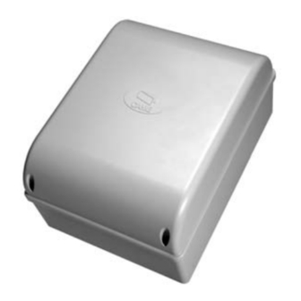
CAME ZA3P Installation Manual
Control panel for 230vgearmotors
Hide thumbs
Also See for ZA3P:
- Installation manual (13 pages) ,
- Installation manual (49 pages) ,
- User manual
Advertisement
Advertisement
Table of Contents

Summary of Contents for CAME ZA3P
- Page 1 Control panel FA01079-EN for 230Vgearmotors ZA3P EN English INSTALLATION MANUAL...
- Page 2 Any other use is dangerous. CAME S.p.A. is not liable for any damage caused by improper, wrongful and unreasonable use. • Before installing the control panel, make sure that the gui-...
- Page 3 be effective. • All maintained-action switches that are connected to the control panel must be positioned so that the maneuvering area is completely visible from the switches, yet far enough away from any moving parts. • Make sure that the operator has been properly adjusted and that any associated safety and protection devices, as well as the gearmotor's manual release, are working properly.
-
Page 4: Technical Data
The settable control modesare: - opening/closing; - opening/closing in maintained action; Intended use Model Operator ZA3P ATI - FAST - FERNI - FROG - KRONO Any installation and/or use other than that specified in this manual is forbidden. Technical data Fuse table Type... -
Page 5: Description Of Parts
Description of parts Connection terminals Time settingtrimmer Control board fuse Featuresselectors Fusefor control devices AF radio frequency card slot Accessories fuse 24 V warningLED Electric-lock fuse Transformer LED programmazione Condensers* Radio code memorizing buttons ⑬ ⑫ 12 24 ⑧ 0 12 24 ③... -
Page 6: Installation
Cable type and minimum section cable length Connection < 20 m 20 < 30 m Control panel power-supply 3G x 1.5 mm 3G x 2.5 mm Motor power supply 4G x 1.5 mm 4G x 2.5 mm Signaling devices 2 x 0.5 mm2 Command and control devices 2 x 0.5 mm2 Safety devices (photocells) -
Page 7: Input Voltage
Limit-switch contacts (N.C.) Came gearmotors standard set opening scheme. With gates with only one leaf, connect the gearmotor to W X Y (M2) regardless of the side it is fi tted on (for FROG, if necessary, invert connections X and Y);... - Page 8 Warning and lighting devices Gate open warning-light - For warning that the gate is open. It stops fl ashing when the gate closes. Movement warning fl ashing-light - Itfl ashes when the gate is opening and closing. CONTACTS rated for 230V - 25W max.
-
Page 9: Safety Devices
Safety devices Delta Dir/DeltaS <- C1 -> Connection for reopening during closing (N.C. contact). - With safety device such as photocells, sensitive safety- edges and other devices. During closing, the contact triggers an inversion of movement until the gate is completely open. - Page 10 Functions selection Selector 1 ON Automatic closing enabled (1 OFF-disabled); 2 ON "Open-stop-close-stop" with button (2-7) and radio-control (AF card fi tted) enabled; 2 OFF“Open-close” with button (2-7) and radio control (AF card fi tted) enabled; 3 ON “Only open” and radio control (AF card fi tted) enabled (3 OFF-disabled); 4 ON Pre-fl...
- Page 11 ENABLING THE RADIO CONTROL Antenna and AF radiofrequency card Connect the RG58 antenna-cableto the corresponding terminals. FC1 FA2 FC2 Fit the radio-frequency card intothe slot on the control board AFTER CUTTING OFF THE MAINS POWER SUPPLY. N.B.: The control board recognizes the radiofrequency card only when it is powered up.
-
Page 12: Final Operations
These must therefore be disposed of by authorized, certified professional services. DISPOSE OFRESPONSIBLY! REFERENCE REGULATIONS CAME SpA declares that this product complies with the current directives at the time it is manufactured. The contents of this manual may change, at any time, and without notice. CAME S.p.A.


Need help?
Do you have a question about the ZA3P and is the answer not in the manual?
Questions and answers