Table of Contents
Advertisement
Quick Links
Advertisement
Table of Contents

Related Manuals for TOORX ERX900


Summary of Contents for TOORX ERX900
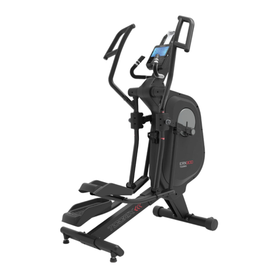
- Page 1 INSTRUCTION...
- Page 2 Front stabilizer Main frame Console supporting tube Console supporting tube cover (L&R) Rear stabilizer R(A9) L(A8) Console (G1) Front pedal supporting &Console cover (G2) tube cover (A66) Adaptor (A67) E2 Handle bar (R) E1 Handle bar (L) Central supporting tube Pedal supporting tube cover (L1&L2),(R1&R2) L2(A73)
- Page 3 TOOL M6x2 (F4) Screw M8 (F2) Screw M8x65 (A107) Bolt Ø15x50.5 (F3) Washer M8 (A62) Spring washer M8 (A61) Washer M8 (A78) Screw M3x20 (A63) Screw M8x20...
- Page 4 FRONT STABILIZER (B) ASSEMBLY Step 1. Remove the four preassembled screws (B3), spring washer (B4) and washer (B5) from the front stabilizer (B). Step 2. Attach the front stabilizer (B) on to main frame (A) with screws (B3), spring washer (B4) and washer (B5). USE TOOL:6m/m Step 1.
- Page 5 CENTRAL SUPPORTING TUBE (F) ASSEMBLY Step 1. Attach the central supporting tube (F) onto main frame (A) with four screws (F4). Tighten the screws (F4) on the central supporting tube when the unit is lifted. USE TOOL:6m/m REAR STABILIZER (C) ASSEMBLY Step 1.
- Page 6 CONSOLE & CONSOLE COVER ASSEMBLY Step 1. Remove four screws (G3) from the console (G). Step 2. Connect all wires. Step 3. Fit the console (G) to console supporting tube (D). Step 4. Slide the console cover (G2) on console supporting tube (D). Step 5.
- Page 7 FRONT CONNECTING SHAFT (A53) & FRONT PEDAL SUPPORTING TUBE-L&R (A64&A65) ASSEMBLY Step 1. Attach front connecting shaft (A53) and front pedal supporting tube-L (A64) using bolt (A107), screw (A63) spring washer (A62) and washer (A61). ** Repeat same step to finish right side assembly. A107 USE TOOL:6m/m PEDAL TUBE COVER-(L&R) ASSEMBLY...
- Page 8 HANDLE BAR & FRONT PEDAL SUPPORTING TUBE COVER ASSEMBLY Step 1. Remove the six preassembled screws (E4&E5) from the handle bar (E1). Step 2. Remove the two preassembled screws (A108) from the main frame (A). Step 3. Mount the handle bar (E1) onto the main frame (A) with screws (E4&E5).
- Page 9 HOW TO TRANSPORT THE MACHINE If the machine needs to be transported to a different location, lift up the rear stabilizer until the front transportation wheels engage the ground. You may now move the machine to the desired location. After the move, gently set the machine down at its new location and adjust the levelers on the bottom rear stabilizer to level the machine if needed.
- Page 10 HOW TO ADJUST THE STRIDE Step 1. There are 2 different stride choices on the 1280ef. They are 17” and 22”. (When you choose 17”, you will see the orange sticker on front pedal supporting tube, when you choices 22”, you will see the white sticker on front pedal supporting tube.) Step 2.
-
Page 11: Button Functions
BUTTON FUNCTIONS To make upward adjustment to each function data or increase training resistance. DOWN To make downward adjustment to each function data or decrease training resistance. ENTER To co rm all settings. START / STOP To start or stop workout. Press the START/ STOP under standby mode, it can be a quick start key to the Manual Program. -
Page 12: Display Functions
DISPLAY FUNCTIONS TIME Time will count up from 00:00 to maximum 99:59 with each increment is 1 minute. SPEED Displays current training speed. Maximum speed is 99.9 KM/H or ML/H. Displays the Rotation Per Minute. Display range 0~999 RPM DISTANCE Accumulates total distance from 0:0 up to 999.9 KM or ML. - Page 13 FIGURE 5 Then go to Calendar & CLOCK setting (Figure 3~5), set the CLOCK and Calendar by pressing UP or DOWN and con rm by ENTER button. 2. User may press the UP or DOWN to select User 1~4 and press ENTER for co ation (FIGURE 6).
-
Page 14: Operation Procedure
OPERATION PROCEDURE Program selections are MANUAL PROGRAM USER PROG WATT H.R.C. (FIGURE 11~15). FIGURE 11 FIGURE 12 FIGURE 13 FIGURE 14 FIGURE 15... -
Page 15: Manual Mode
QUICK START IN MANUAL 1. Press ENTER into MANUAL program (FIGURE 16). 2. Press START/STOP to start exercising (FIGURE 17). The resist level is adjustable during exercising. 3. User can press START/ STOP to stop exercising. FIGURE 16 FIGURE 17 MANUAL MODE 1. - Page 16 FIGURE 20 FIGURE 21 FIGURE 22 FIGURE 23 FIGURE 24 FIGURE 25 FIGURE 26 FIGURE 27...
-
Page 17: User Program Mode
FIGURE 28 FIGURE 29 FIGURE 30 FIGURE 31 USER PROGRAM MODE 1. After enter USER PROGRAM mode (FIGURE 32), the column of the pr is blinking (FIGURE 33). User may press UP or DOWN to adjust the resistance level to create his / her own pro le. -
Page 18: Watt Mode
FIGURE 34 WATT MODE 1. After enter WATT mode (FIGURE 35), the preset watt value 120 is ashing on screen, use UP or DOWN to set target value from 10 to 350 (FIGURE 36). Pressing START button to start training. 2. - Page 19 HEART RATE CONTROL MODE 1. After enter HEART RATE CONTROL mode (FIGURE 38), the screen will show heart rate percentage 55%, 75%, 90% and TARGET (FIGURE 39~42). User may select heart rate percentage by pressing UP or DOWN for training. 2.
- Page 20 RECOVERY After exercising for a period of time, keep holding on handgrips and press “RECOVERY” button. All function display will stop except “TIME” starts counting down from 00:60 to 00:00 (FIGURE 44). When the console detect pulse signal, LCD will display “RECOVERY SCANNING”; While no pulse input, LCD will remind with displaying “PULSE INPUT!”...
- Page 21 FIGURE 48 FIGURE 49 FIGURE 50 FIGURE 51 FIGURE 52 FIGURE 53 FIGURE 54 FIGURE 55...
- Page 22 FIGURE 56 FIGURE 57 FIGURE 58 FIGURE 59 FIGURE 60 Bluetooth connecting & USB power charger icon drawing (FIGURE 61& FIGURE 62) FIGURE 61 FIGURE 62...
-
Page 23: Battery Installation
BATTERY INSTALLATION The battery is placed in order to keep the calendar running. If user would like to adjust the calendar, need to remove the battery and re-power the console before resetting the calendar (FIGURE 63). FIGURE 63 AA 1.5V x 2PCS 1) Loosen the knob of the battery cover. - Page 24 STREAM THE WORKOUT NOTICE This console is equipped with a bluetooth interface. Please take note that your mobile device needs to be compatible with the bluetooth interface (bluetooth 4.0). To use training apps you will have to activate the bluetooth function on your mobile device (tablet or smart phone) and start the tnsee app.
- Page 25 GARLANDO SPA Via Regione Piemonte, 32 - Zona Industriale D1 15068 - Pozzolo Formigaro (AL) - Italy www.toorx.it - info@toorx.it...
Need help?
Do you have a question about the ERX900 and is the answer not in the manual?
Questions and answers