
Related Manuals for Hettich ROTANTA 460 Robotic


Summary of Contents for Hettich ROTANTA 460 Robotic
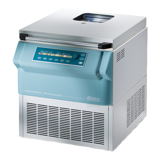
- Page 1 ROTANTA 460 Robotic Operating Instructions Rev. 02 / 12.2022 Andreas Hettich GmbH & Co. KG AB5680EN_US...
- Page 2 Fig. 1 START PROG T/°C t/min 4500 12:30 STOP PROG T/°C TIME OPEN Fig. 2 ROTANTA 460 Robotic 2/53 Rev. 02 / 12.2022 AB5680EN_US...
- Page 3 Standards and regulations which apply to this device The device is a high-end technical product. It is subject to extensive testing and certification procedures according to the following standards and regulations in their respectively valid version: Electrical and mechanical safety for design and final testing: Standard series: IEC 61010 (conform to standards of DIN EN 61010) ...
- Page 4 Single Registration Number: DE-MF-000010680 © 2009 by Andreas Hettich GmbH & Co. KG All rights reserved. No part of this publication may be reproduced without the prior written permission of the copyright owner. Modifications reserved! AB5680EN_US / Rev. 02 4/53 Rev.
-
Page 5: Table Of Contents
Contents Intended use ................................8 Remaining risks ..............................8 Technical specifications ............................8 Notes on safety..............................10 Symbol meanings ..............................12 Delivery checklist ..............................13 Transport and storage............................15 Transport ...............................15 Storage ................................15 Unpacking the centrifuge ............................15 Initial operation ..............................16 Interface ................................17 Hatch for loading and unloading the device ......................17 11.1 Opening the hatch............................17 11.2... - Page 6 19.4.3 Calling up program linkage .........................30 19.5 Automatic temporary storage ........................30 Centrifugation..............................30 20.1 Centrifugation with preselected time ......................31 20.2 Continuous operation..........................31 20.3 Short-time centrifugation ..........................31 Change the settings during the centrifugation run.....................31 Integral RCF..............................32 22.1 Query integral RCF ............................32 22.2 Activate or deactivate the integral RCF display..................32 Emergency Stop..............................32 Cycle counter ..............................33...
- Page 7 42.2.3 Removal of radioactive contaminants ....................47 42.2.4 Trunnions ............................47 42.2.5 Rotors and accessories with limited service lives ................48 42.3 Autoclaving ..............................48 42.4 Centrifuge containers ..........................48 Faults ................................49 Returning Devices .............................51 Disposal ................................51 Anhang / Appendix ............................52 46.1 Rotoren und Zubehör / Rotors and accessories..................52 AB5680EN_US Rev.
-
Page 8: Intended Use
Intended use also includes observing all instructions in the Operating Manual and compliance with the required inspection and maintenance work. Any other use or use beyond this is considered improper. Andreas Hettich GmbH & Co. KG shall not be liable for any damage arising from this. - Page 9 Andreas Hettich GmbH & Co. KG Manufacturer D-78532 Tuttlingen Model ROTANTA 460 Robotic Basic-UDI-DI 4050674010017QF 5680 5680-08 5680-05 5680-01 5680-04 5680-RS232 5680-08-RS232 5680-05-RS232 5680-01-RS232 5680-04-RS232 5680-10 5680-18 5680-15 5680-11 5680-14 Type 5680-10-RS232 5680-18-RS232 5680-15-RS232 5680-11-RS232 5680-14-RS232 5680-30-A 5680-38-A 5680-35-A 5680-31-A...
-
Page 10: Notes On Safety
Notes on safety No claim of warranty will be considered by the manufacturer unless ALL instructions in this manual have been followed. Reports of serious incidents involving the device Report any serious incidents involving the device to the manufacturer and, if necessary, to the competent authority. To avoid serious or fatal injury, read and comply with the following safety precautions. - Page 11 With centrifuges for robotic use please pay attention the notes of the key operated switch. Spare parts Only original spare parts and original accessories licensed by the Andreas Hettich GmbH & Co. KG company are allowed to be utilised.
-
Page 12: Symbol Meanings
Symbol meanings Symbol on the device: Attention, general hazard area. Symbol on the device: Observe operating instructions. This symbol indicates that the user must observe the operating instructions provided. Symbol in this document: Attention, general hazard area. This symbol refers to safety relevant warnings and indicates possibly dangerous situations. The non-adherence to these warnings can lead to material damage and injury to personal. -
Page 13: Delivery Checklist
Symbol on the shipping carton label: Stack limit. Maximum number of identical packages which may be stacked on the bottom package, whereby “n“ stands for the number of permissible packages. The bottom package is not included in “n”. Delivery checklist Centrifuge type 5680, 5680-01,... - Page 14 Centrifuge type 5680, 5680-01, 5680-30-A, 5680-30-D, 5680-40, 5680-RS232 5680-10-RS232 5680-70, 5680-08, 5680-04, 5680-31-A, 5680-31-D, 5680-41, 5680-01- 5680-11-RS232 5680-71, 5680-10, 5680-05, 5680-34-A, 5680-34-D, 5680-44, RS232 5680-14-RS232 5680-74, 5680-18 5680-11, 5680-35-A, 5680-35-D, 5680-45, 5680-04- 5680-15-RS232 5680-75, 5680-14, 5680-38-A, 5680-38-D 5680-48 RS232 5680-18-RS232 5680-78 5680-15 5680-05-...
-
Page 15: Transport And Storage
Transport and storage Transport NOTICE Material damage due to lack of transport securing. Damage to the centrifuge and its components. Install the transport securing device before each transport. When the device and accessories are transported, the following ambient conditions must be complied with: ... -
Page 16: Initial Operation
Initial operation A type B residual current circuit breaker must be used if the device is additionally protected with a residual current circuit breaker in the building installation. When using a different type, the residual current circuit breaker may either not switch off the unit if there is a fault on the unit, or it may switch off the unit even though there is no fault on the unit. -
Page 17: Interface
Interface The device is either equipped with an RS232 or an optical interface. IOIOI The RS232 interface is labeled with the symbol. RS232 IOIOI The optical interface is labeled with the symbol. OPTICAL The centrifuge can be controlled and data queried via this interface. The LED in the key lights up during data communication. -
Page 18: Hatch With Light Barriers (Only For Centrifuges With Light Barriers)
11.3 Hatch with light barriers (only for centrifuges with light barriers) Optionally, the hatch can be equipped with light barriers to protect the hands of the operator and robot arm. Light barrier for protecting hands This light barrier (A) is in the area right before the hatch is closed. The hatch drive stops immediately if the operator reaches into the hatch with his hands in the light barrier area. -
Page 19: Installation And Removal Of The Rotor
Installation and removal of the rotor Clean the motor shaft (C) and the rotor drilling (A), and lightly grease the motor shaft afterwards. Dirt particles between the motor shaft and the rotor hinder a perfect seating of the rotor and cause an irregular operation. ... -
Page 20: Inserting And Removing Hangers Into/From The Rotor
Check the rotor to make sure it is seated firmly. Grease the lifting lug (C) (Hettich lubricating grease, no. 4051). Insert hangers (A) into the rotor. While doing so, make sure that the lifting lugs (C) are in the grooves (B) of the hangers. -
Page 21: Loading The Rotor
Loading the rotor CAUTION Injury and property damage due to containers of glass Standard centrifuge containers of glass will not stand RCF values exceeding 4000 (DIN 58970, pg. 2). Use centrifuge containers of a different material. Check the rotor for firm seating. With swing-out rotors all rotor positions must be lined with identical hangers. - Page 22 The maximum filling quantity for the centrifuge containers specified by the manufacturer must not be exceeded. In the case of angle rotors, the centrifuging Fluid vessels may only be filled so far that no fluid can be expelled from them while the centrifuge is running.
-
Page 23: Control And Display Elements
Control and display elements See figure on page 2. Fig. 2: Display and control panel 17.1 Control knob For setting the individual parameters. Turning anticlockwise reduces the value. Turning clockwise increases the value. 17.2 Keys and setting options Running time, parameters t/hms. TIME h: hours. - Page 24 Temperature T/°C Adjustable in degrees Celsius (°C) or in degrees Fahrenheit (°F). For setting the temperature unit, see chapter "Temperatur-Einheit einstellen/Setting the temperature unit". Parameters T/°C = degrees Celsius (°C). Adjustable from -20°C to +40°C, in 1°C increments. Parameters T/°F = degrees Fahrenheit (°F). Adjustable from 4°F to +104°F, in 1°F increments.
-
Page 25: Enter Centrifugation Parameters
Enter centrifugation parameters Parameters can be input via the operating unit (key position "0") or via the interface (key position "LOCK 2"). The functions of the various key positions are described in the "Key-operated switch" chapter. If no key is pressed for 8 seconds long after the selection or during the input of parameters, the previous values will be shown in the display. -
Page 26: Relative Centrifugal Force (Rcf) And Centrifuging Radius (Rad)
18.4 Relative centrifugal force (RCF) and centrifuging radius (RAD) Relative centrifugal force (RCF) depends on the centrifugal radius (RAD). Before RCF is set, the centrifugal radius has to be set. Press the key as often as is required until the parameters RAD and RCF are displayed and the value of the parameter, RAD is displayed in parentheses, ... -
Page 27: Braking Stage And Run-Down Time
18.5.2 Braking stage and run-down time No B-brake stages can be set for this device. The activation of the B-brake stages in the "Settings" menu is not possible (parameter B-Ramp = off). B-brake stages are similar to an exponential braking curve. It is only possible to set run-down times if these have been activated. -
Page 28: Programming
Programming Programming can be done via the operating unit (key position "0") or via the interface (key position "LOCK 2"). The functions of the various key positions are described in the "Key-operated switch" chapter. If parameters are changed, the program place number is displayed in parentheses (). This means that the centrifugation data in the display no longer corresponds to the centrifugation data from the program place that has been saved. -
Page 29: Program Linkage
19.4 Program linkage "Program linkage" can be used to link several centrifuge operations together. A program linkage is only possible if this has been activated (parameter Multi programs = on; see the chapter on "Activating or deactivating program linkage"). 19.4.1 Activating or deactivating program linkage The program link can be activated/deactivated as follows when the rotor is at a standstill: This setting can only be made via the operating unit (key position "0"... -
Page 30: Calling Up Program Linkage
For program linkages which consist of 20 programs, END cannot be set after the 20th program. 10. Press the button. STO B, for example, is displayed. START 11. Press the button to save the program linkage. START As confirmation, Multi program store .. will be shown briefly. 19.4.3 Calling up program linkage ... -
Page 31: Centrifugation With Preselected Time
20.1 Centrifugation with preselected time Set the centrifugation parameters or call up a program or a program linkage (see the chapters on "Enter centrifugation parameters", "Calling up programs" or "Program linkage"). Press the key. The LED in the key blinks until the rotor has been imported, it is subsequently lit. -
Page 32: Integral Rcf
Integral RCF The integral RCF is a measure for the effect of sedimentation (∫ n dt). This numerical value is used to compare centrifugation runs. 22.1 Query integral RCF The integral RCF can be queried via the operating unit (key position "0") or via the interface (key position "LOCK 2"). -
Page 33: Cycle Counter
Cycle counter The settings can be made via the operating unit (key position "0" or "LOCK 2") or via the interface (key position "LOCK 2"). The functions of the various key positions are described in the "Key-operated switch" chapter. Usage of the cycle counter only makes sense if you always use the same hanger set. The centrifuge is fitted with a cycle counter, which counts the rotor cycles (centrifugation runs) of the different rotor codes (see also chapter, "Rotor recognition"). -
Page 34: After Starting The First Centrifugation Run, Enter The Maximum Permitted Number Of Cycles Or Deactivate The Ycle Counter
24.1 After starting the first centrifugation run, enter the maximum permitted number of cycles or deactivate the cycle counter Enter max cycles = 30000 is displayed. Use the knob to set the maximum permitted number of rotor cycles specified on the hanger. For rotors and hangers which are not labelled with the maximum permissible number of running cycles, the cycle counter can be deactivated. -
Page 35: Activating Or Deactivating The Cycle Counter
24.3 Activating or deactivating the cycle counter The cycle counter can be activated/deactivated as follows when the rotor is at a standstill: You can scroll backwards through the menu by pressing the key. T/°C The operation can be cancelled at any time by pressing the key. -
Page 36: Activating Or Deactivating Start-Up And Run-Down Times
Activating or deactivating start-up and run-down times The start-up and run-down times can be activated or deactivated as follows with the rotor at a standstill: This setting can only be made via the operating unit (key position "0" or "LOCK 2"). The functions of the various key positions are described in the "Key-operated switch"... -
Page 37: Displayed Centrifugation Data After Switch-On
Displayed centrifugation data after switch-on. After switch-on the centrifugation data from program 1, or from the last program that was used, is displayed. If the rotor is at standstill, this can be set as follows: This setting can only be made via the operating unit (key position "0" or "LOCK 2"). The functions of the various key positions are described in the "Key-operated switch"... -
Page 38: Backlighting Of The Display
Backlighting of the display (only possible starting from program version V 01.18) To save energy, it can be set that, after a centrifugation run, the backlighting of the display switches off after 2 minutes. With the rotor at a standstill, this can be set as follows: This setting can only be made via the operating unit (key position "0"... -
Page 39: Query The System Information
Query the system information The following system information can be queried: Centrifuge model Mains voltage Rotor information Program version of the centrifuge Program version of the frequency converter The system information can be queried as follows when the rotor is at a standstill: The query can be made via the operating unit (key position "0"... -
Page 40: Cooling (Only In Centrifuges With Cooling)
Cooling (only in centrifuges with cooling) The temperature set-point can be adjusted from -20°C to +40°C / -4°F to +104°F. The lowest obtainable temperature is dependent on the rotor (see Chapter "Anhang/Appendix, Rotoren und Zubehör/Rotors and accessories"). 35.1 Standby-cooling When the rotor is at a standstill, with the lid and hatch closed, the centrifuging chamber is cooled to the preselected temperature if this is lower than 20°C / 68°F. -
Page 41: Prevent Cooling Being Switched On During Run-Out
35.4 Prevent cooling being switched on during run-out If necessary it can be set so that at the end of the centrifugation run during run-out, once the specified speed has been attained, cooling is not switched on. This avoids whirling up the sediment in the sample. The speed can be set between 0 RPM and the maximum speed of the rotor (Nmax) in increments of 10. -
Page 42: Key-Operated Switch
Key-operated switch NOTICE Material damage due to operation by unauthorised personnel. When the key switch is in the "Teach" position, unauthorised personnel may cause damage to property. Only authorized skilled personnel may operate the device in the "TEACH" key position. ... -
Page 43: Setting Rotor Position 1
Setting rotor position 1 NOTICE Material damage due to operation by unauthorised personnel. Only authorized skilled personnel may set rotor position 1. If the rotor was changed and if this has another rotor code than the previously used rotor, a rotor detection procedure must be carried out first before rotor position 1 is set (see chapter "Rotor recognition"). -
Page 44: Centrifugation Of Materials Or Mixtures Of Materials With A Density Higher Than 1.2 Kg/Dm
Centrifugation of materials or mixtures of materials with a density higher than 1.2 kg/dm When centrifuging with maxim revolutions per minute the density of the materials or the material mixtures may not exceed 1.2 kg/dm The speed must be reduced for materials or mixtures of materials with a higher density. The permissible speed can be calculated using the following formula: Reduced speed... -
Page 45: Emergency Release
Emergency release During a power failure the lid cannot be unlocked by motor. An emergency release has to be executed by hand. WARNING Risk of injury and material damage due to flying parts and moving rotor. If the device is opened while the rotor is still moving, components may fly out and there is a risk of injury from the moving rotor. -
Page 46: Centrifuge (Housing, Lid And Centrifuging Chamber)
42.1 Centrifuge (housing, lid and centrifuging chamber) 42.1.1 Surface cleaning and care Clean the centrifuge housing and the centrifuging chamber regularly, using soap or a mild detergent and a damp cloth if required. For one thing, this services purposes of hygiene, and it also prevents corrosion through adhering impurities. -
Page 47: Disinfection
The rotors and accessories must be dried directly after removing the radioactive contaminants. 42.2.4 Trunnions With swing-out rotors the trunnions must be regularly lubricated (Hettich Lubricating Grease No. 4051) in order to ensure consistent swinging out of the hangers. AB5680EN_US Rev. -
Page 48: Rotors And Accessories With Limited Service Lives
42.2.5 Rotors and accessories with limited service lives The use of certain rotors, hangers and accessory parts is limited by time. These are marked with the maximum permitted number of operating cycles or with an expiration date and the maximum permitted number of operating cycles or just with the expiration date; e.g.: - "einsetzbar bis Ende: ... -
Page 49: Faults
Faults If the fault cannot be eliminated with the help of the fault table, please inform Customer Service. Please specify the type of centrifuge and the serial number. Both numbers can be found on the name plate of the centrifuge. Perform a MAINS RESET: ... - Page 50 Message / fault Cause Remedy FU / CCI - ERROR 60, 61.2- Error / defect electronics / motor 61.20, Perform a MAINS RESET. 61.128- 61,131, Check supply voltage. FU / CCI - ERROR 61.1 Supply voltage is too low Error / defect electronics / motor ...
-
Page 51: Returning Devices
Install the transport securing device before each transport. If the device or its accessories are returned to Andreas Hettich GmbH & Co. KG, in order to provide protection for people, the environment and materials, it has to be decontaminated and cleaned before being shipped. -
Page 52: Anhang / Appendix
Anhang / Appendix 46.1 Rotoren und Zubehör / Rotors and accessories 4426-R/4 4467-R/4 4444 4463-R/4 4464-R/4 4486-R/4 4488-R/4 4490-R/4 4426-RA/4 4467-RA/4 Ausschwingrotor 4-fach / Swing out rotor 4-times 90° Max. Laufzyklen / max. cycles 400000 Jahre / Verwendungsdauer / service life years Max. - Page 53 5622 5631-R/2 5633-R/2 5636-R/2 Ausschwingrotor 2-fach / Swing out rotor 2-times 90° Max. Laufzyklen / max. cycles 400000 Jahre / Verwendungsdauer / service life years Max. Laufzyklen / max. cycles 70000 50000 60000 Max. Beladung / max. load Drehzahl / speed 6200 RZB / RCF max.
Need help?
Do you have a question about the ROTANTA 460 Robotic and is the answer not in the manual?
Questions and answers