
Related Manuals for Hettich ROTANTA 46 RSC ROBOTIC


Summary of Contents for Hettich ROTANTA 46 RSC ROBOTIC
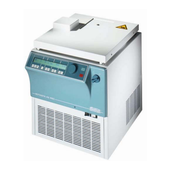
- Page 1 ROTANTA 46 RSC ROBOTIC Repair instructions 2008 Andreas Hettich GmbH & Co. KG AR4817EN...
- Page 2 (07461) 705-0 (07461) 705-125 info@hettichlab.com, service@hettichlab.com www.hettichlab.com © 2008 by Andreas Hettich GmbH & Co. KG All rights reserved. No part of this publication may be reproduced without the prior written permission of the copyright owner. Modifications reserved! AR4817EN / 2008...
-
Page 3: Table Of Contents
Contents Introduction ......................7 Symbol meanings..................... 7 Disposal ........................8 Operational modes....................8 Description of the centrifuge..................9 Control panel (A5) ..................... 9 Supply board (A1) ................... 10 Frequency converter (A2) ................11 Positioning board (A14)................... 11 Sliding hatch board (A15)................12 Special features .................... - Page 4 Error messages ..................... 20 MAINS RESET ....................20 Brief description ....................20 Description and elimination of errors .............. 23 Settings and interrogations ..................47 Option: program linkage ................. 47 8.1.1 Linking programs ..................47 8.1.2 Changing program links................48 8.1.3 Centrifugation run with program linking ...........
- Page 5 8.21 Immediate display of the centrifugation data after switching on ...... 63 8.22 Logging ......................64 8.22.1 Error messages..................64 8.22.2 Imbalance messages ................65 8.22.3 Modification logs ..................65 8.22.4 Note on the display of date and time............65 8.23 Setting the display contrast ................
- Page 6 10.19 Appliance plug (X1) and overvoltage protection (F1) ........83 10.20 Mains switch (F3) (with integrated overcurrent cutout)........ 83 10.21 Lid lock (Y1) ....................83 10.21.1 Left lid lock ................... 83 10.21.2 Right lid lock..................84 10.22 Pneumatic spring ..................84 10.23 Sealing ring (between the upper part of the centrifuge housing and the lid) ....................
-
Page 7: Introduction
In such an event any guarantee claim or liability claim against the Andreas Hettich GmbH & Co. KG company expire. • Only original spare parts and original accessories licensed by the Andreas Hettich GmbH & Co. KG company are allowed to be utilised. -
Page 8: Disposal
Symbol on the machine and in this document: Symbol for the separate collection of electric and electronic devices according to the guideline 2002/96/EG (WEEE). The device belongs to Group 8 (medical devices). Applies in the countries of the European Union, as well as in Norway and Switzerland. -
Page 9: Description Of The Centrifuge
Description of the centrifuge These microprocessor controlled centrifuges mainly consist of the following electrical components: • Control panel, microprocessor controlled • Supply board, microprocessor controlled • Frequency converter (motor control), microprocessor controlled • Motor with speed sensor (speedometer) and imbalance switch •... -
Page 10: Supply Board (A1)
Supply board (A1) The supply board carries out the following tasks: • Current supply 18 V DC and 5 V DC for the supply board • Current supply 18 V DC for the control panel • Temperature measurement and evaluation of the temperature sensor at the bottom of the centrifuge chamber •... -
Page 11: Frequency Converter (A2)
Frequency converter (A2) The frequency converter carries out the following tasks: • Generating the motor current supply (three-phase current with variable frequency and voltage). Functional description: The supply voltage is rectified, smoothened and chopped into a pulse width pattern in three bridge elements with a microprocessor. -
Page 12: Sliding Hatch Board (A15)
Sliding hatch board (A15) Plugging station and transmission for: • drive motor for hatch • hatch end switches (S6, S7) • micro switch "lid contact" (S8) Special features • The solenoid of the lid lock is switched via a relay on the supply board. This relay can pick up only if the control panel and the supply board have detected a standstill. -
Page 13: Magnetic Brake (Y2)
Magnetic brake (Y2) • The magnetic brake on the motor fixes the rotor during it will be loaded and unloaded. • The brake will be activated when the desired rotor position is reached and remains activated until moving to the next rotor position or closing the hatch. 5.10 Lid lock (Y1) •... -
Page 14: Machine Concept
5.15 Machine concept • The machine version is set with jumper assignment A.4 and A.5 on the coding strip of the supply board, see chapter "Setting the machine and cooling version". • This machine version must comply with the control panel (correct initialization). •... -
Page 15: Diagram Of The Cooling Versions
Temperature determination: During centrifugation the temperature is determined on the basis of the relationship between T1 and T2. This occurs in different ways depending on the speed range (see chapter "Diagram of the cooling versions, sensor evaluation"). During standstill, the temperature is determined only with the T2 temperature sensor. -
Page 16: Ventilator Control
5.17 Ventilator control • The ventilator control is a temperature-dependent phase control. • If the cooling system switches on, the ventilators run with a fixed start speed. • When the condenser temperature rises, the ventilators run faster. • At 32 °C, or at the latest after 60 seconds, the ventilator speed regulation is activated and the ventilator speed is regulated to achieve a constant temperature of 34°C at the condenser. -
Page 17: Safety Devices
5.20 Safety devices ⇒ overvoltage protection Mains input ⇒ with thermal overload protection Mains switch ⇒ between supply board and frequency converter Radio interference suppression filter Frequency converter ⇒ electronically protected ⇒ overtemperature switch > 135 °C Motor ⇒ overtemperature switch in the centrifuge chamber, software Cooling system monitoring of the temperature sensor T3 on the condenser ⇒... -
Page 18: Key-Operated-Switch Position Lock 2
The PC uses this address to communicate with the centrifuge. This serial address can be compared with the name of a person. Each address in a system can only be given ONCE. In the Hettich-BUS system there can be managed up to 29 centrifuges. -
Page 19: Troubleshooting Procedures
Troubleshooting procedures • Fuses in installation in which centrifuge is installed are intact. • Supply voltage present at (see connecting diagram): − Connecting cable − Appliance plug − Overvoltage protection (F1) − Mains switch (Q1) − Supply board, plugs X21 and X29. •... -
Page 20: Error Messages
Error messages MAINS RESET • Switch off the mains switch. • Wait for 10 seconds and then switch on the mains switch again. Brief description Error designation No. Brief description Page TACHO-ERROR Speedometer pulses break down during rotation TACHO-ERROR No speedometer pulses after start command IMBALANCE (03) Imbalance on motor axle CONTROL-ERROR... - Page 21 Error designation No. Brief description Page CONTROL-ERROR 26 Incorrect feedback, control panel input do not recognize the expected signal SER I/O-ERROR 30 No connection between control panel and serial interface SER I/O-ERROR 31 No connection between frequency converter and serial interface SER I/O-ERROR 32 No connection between supply board and serial interface...
- Page 22 Error designation No. Brief description Page FU/CCI-ERROR 60 Faulty release signal to frequency converter FU/CCI-ERROR 61 Frequency converter - error: computing section FU/CCI-ERROR 62 Frequency converter - error: undervoltage FU/CCI-ERROR 63 Frequency converter - error: overcurrent FU/CCI-ERROR 64 Frequency converter - error: overvoltage 65 Frequency converter - error: I ∗...
-
Page 23: Description And Elimination Of Errors
Description and elimination of errors TACHO - ERROR 01 Error During centrifugation the speedometer pulses are interrupted. Consequences The rotor slows down until it stops. of the error After the rotor stops, there is a DC braking for 30 sec. A MAINS RESET during slowing-down causes a DC braking for 3 minutes. - Page 24 IMBALANCE (03) Error Imbalance on the motor axle. Consequences The centrifuge slows down until the “open the lid” release occurs. of the error Further cooling until the SET temperature is achieved. Cause of error • Weight difference in the rotor components •...
- Page 25 CONTROL - ERROR 06 Error Lid lock message is faulty. Control panel indicates: lid lock open Supply board indicates: lid lock closed Consequences The centrifuge slows down until the “open the lid” release occurs. of the error Further cooling until the SET temperature is achieved. Cause of error •...
- Page 26 CONTROL - ERROR 09 Error Standstill message is faulty. Control panel indicates: no standstill Supply board indicates: standstill Consequences Braked slow-down. of the error Further cooling until the SET temperature is achieved. Cause of error • Flat ribbon cable to the control panel (A5) is defective •...
- Page 27 VERSION - ERROR 12 Error Differences in the initialization of supply board (jumper assignment A.0 – A.7), control panel (EPROM) or frequency converter. − VERSION – ERROR 12 also appears after CONTROL – ERROR 92 is displayed Consequences Further operation is not possible. of the error Cause of error •...
- Page 28 CONTROL - ERROR 26 Error Incorrect feedback, control panel input does not recognize the expected signal. Consequences The centrifuge stops with error message. of the error Cause of error • Control panel (A5) is defective. • Supply board (A1) is defective •...
- Page 29 SER I/O - ERROR 32 Error The control panel has no connection to the component supply board via the serial interface. Consequences The centrifuge slows down until the “open the lid” release occurs. of the error Cause of error • The false machine or cooling version is set on the supply board (A1). •...
- Page 30 SER I/O - ERROR 35 Error The control panel does not receive correct data from the supply board. Consequences The centrifuge slows down until the “open the lid” release occurs. of the error Cause of error • Flat ribbon cable to the control panel (A5) is defective •...
- Page 31 POS-ERROR 40 Error Incremental encoder: positioning information is missing. Defective Track -A- or/and -B-. Rotor turns (speedometer-pulses occur), but the control panel does not recognise any encoder pulses within two rounds or track N (zero pulse) disadjusted. Consequences Further operation is not possible. of the error Cause of error •...
- Page 32 POS-ERROR 41 Error Incremental encoder: positioning information missing. Track N (zero- puls) is defective. Rotor turns (speedometer-pulses occur), but control panel does not recognise zero-pulses within two rounds. Consequences Further operation is not possible. of the error Cause of error • Defective incremental encoder (B7) •...
- Page 33 POS-ERROR 42 Error The drive motor of the hatch is activated but needs too much time to close the hatch completely. 30 s after activating the drive motor the hatch end switch must report “closed“ otherwise the error message will be displayed. Consequences Further operation is not possible.
- Page 34 POS-ERROR 43 Error The drive motor of the hatch is activated but needs too much time to open the hatch completely. 30 s after activating the drive motor the hatch end switch must report “opened“ otherwise the error message will be displayed. Consequences Further operation is not possible.
- Page 35 POS-ERROR 46 Error Position 1 to 4 not reached within 80 sec. 1. Incremental encoder: positioning information is not plausible. Defective Track -A- or/and -B-. 2. Brake for positioning not ok. Brake defective or fuse F1 on the positioning board (A14) has blown.
- Page 36 °C / * - ERROR 50 Error Overpressure in the cooling system (only in centrifuges with an overpressure switch on the plug X11) No overpressure switch has been integrated in the ROTANTA 46 RSC. On the supply board, pin 2 and pin 3 on plug X11 are connected with each other.
- Page 37 °C / * - ERROR 53 Error The temperature sensor at the bottom of the centrifuge chamber has a short circuit or has opened the circuit. Voltage < 0.50 V = short circuit Voltage > 4.50 V = circuit has been opened Consequences The centrifuge slows down until the “open the lid”...
- Page 38 °C / * - ERROR 55 Error The temperature sensor on the condenser has a short circuit or has opened the circuit. Voltage < 0.50 V = short circuit Voltage > 4.50 V = circuit has been opened Consequences The centrifuge slows down until the “open the lid” release occurs. of the error Cooling system is switched off.
- Page 39 °C / * - ERROR 58 Error Temperature deviation too high Consequences The centrifuge slows down until the “open the lid” release occurs. of the error Cooling system is switched off. Cause of error • Temperature range is set too low (see chapter "Parameter for error message °C / *ERROR 58").
- Page 40 FU / CCI - ERROR 61 Error Error in the computing section. Consequences The frequency converter switches off automatically. of the error The rotor slows down unbraked. Further operation is not possible. Further cooling occurs until the set value is achieved. Cause of error •...
- Page 41 FU / CCI - ERROR 64 Error Overvoltage (voltage in the intermediate circuit > 410 V DC). Normally this error occurs only when the drive is being braked. Consequences The frequency converter switches off automatically. of the error The rotor slows down unbraked. Further operation is not possible.
- Page 42 FU / CCI - ERROR 66 I ∗ t - switch off of frequency converter. Error Consequences The frequency converter switches off automatically. of the error The rotor slows down unbraked. Further operation is not possible. Further cooling occurs until the set value is achieved. Cause of error •...
- Page 43 FU / CCI - ERROR 68 Error Overtemperature in the frequency converter Consequences The frequency converter switches off automatically. of the error The rotor slows down unbraked. Further operation is not possible. Further cooling occurs until the set value is achieved. Cause of error •...
- Page 44 CONTROL - ERROR 91 Error Error in the RAM of the S-control panel Consequences Further operation is not possible. of the error Cause of error • S-control panel (A5) is defective. Delete error Carry out a MAINS RESET. code If the error cannot be deleted, replace the S-control panel (A5). CONTROL - ERROR 92 Error Difference in the memory areas of RAM and EEPROM.
- Page 45 CONTROL - ERROR 95 Error Error in program flow: impermissible operating state Consequences Further operation is not possible. of the error Cause of error • Impermissible operating state was determined. • S-control panel (A5) is defective. Delete error Carry out a MAINS RESET. code If the error cannot be deleted, replace the S-control panel (A5).
- Page 46 INDEFINITE Error not specified error. Consequences Further operation is not possible. of the error Cause of error • EPROM is defective • S-control panel (A5) is defective. Delete error Carry out a MAINS RESET. code If error cannot be reset, replace EPROM or S-control panel (A5). BATT Note The battery voltage is measured by the processor:...
-
Page 47: Settings And Interrogations
Settings and interrogations Option: program linkage To activate program linkage, plug a jumper at position B.6 on the coding strip of the supply board. Jumper B.6 aufstecken plug jumper B.6 Option: Programmverknüpfung / option: linking programs Versorgungsplatine A1 supply board A1 Several centrifugation runs can be linked together with the help of the program linking function. -
Page 48: Changing Program Links
8.1.2 Changing program links • Call up the desired program (see operating instructions, chapter "Calling up programs"), change the desired parameters (see operating instructions, chapter "Entering centrifugation parameters"), and save the modified centrifugation data to the same program location (see operating instructions, chapter "Entering / modifying programs"). -
Page 49: Optical Interface
Optical interface A jumper must be plugged at position B.4 on the coding strip of the supply board. Jumper B.4 aufstecken plug jumper B.4 Optische Schnittstelle / optical interface Versorgungsplatine A1 supply board A1 Key-operated switch The key-operated switch is plugged on plug X27 on the supply board (A1). The following program interlocks can be set by the key-operated switch: Left key position: LOCK 1 will be displayed. -
Page 50: Setting The Machine And Cooling Version
Setting the machine and cooling version Set the machine and cooling version of the centrifuge on the supply board by plugging the corresponding jumpers on the coding strip. ROTANTA 46 RSC Maschinen-, Kühlungsversion / machine-, cooling-version Maschinenversion 3 (Jumper A.4, A.5) machine version 3 (jumper A.4, A.5) Kühlungsversion 1 (Jumper A.0) cooling version 1 (jumper A.0) -
Page 51: Prerequisites For The Initialization
8.7.1 Prerequisites for the initialization An initialization can be carried out only if the rotor has standstill and the lid is open. Before the initialization: • Open the lid. • Switch off the mains switch. • Plug the additional jumper on the coding strip of the supply board at position B.1 (see chapter "Function of the additional jumpers"). - Page 52 Action Display / Comment 1. Prepare the centrifuge for initialization (see chapter "Prerequisites for the initialization"). 2. Switch on the mains switch. → CONTROL - ERROR 92 A short acoustic signal sounds to indicate a func- tional check. The display occurs after approx. 30 seconds.
- Page 53 Action Display / Comment → *** OK *** (Frequency converter is initialized) 8. Press the key. START afterwards FU / CCI - TYP 1204 SOFTWARE 203.1 ADDRESS PARAM-INIT 3111 Still no date is set in the S-control panel. → IMBALANCE MODE 1 9.
-
Page 54: Offset Compensation
Set the date and time as described below: 1. Press the key to select the parameter (a: year, mon: month, d: day, h: hours, min: minutes) and make a setting with the control knob . 2. After you have entered all values, press the key in order to save the settings. - Page 55 Action Display / Comment 1. Open the lid. 2. Switch off the mains switch. 3. Plug the additional jumper on the coding strip of the supply board at position B.0 (see chapter "Function of the additional jumpers"). Jumper B.0 aufstecken plug jumper B.0 Offset-Mode / offset-mode Versorgungsplatine A1...
-
Page 56: Imbalance Mode
Imbalance Mode The imbalance mode must be set on the supply board and in the program. 8.9.1 Setting the imbalance mode on the supply board A jumper must be plugged on plug X8 at position pin 3-4 (factory setting), see figure. 8.9.2 Setting the imbalance mode in the program The setting of the imbalance mode can be carried out only if the rotor has standstill and... -
Page 57: Temp. Average Time
8.10 Temp. Average Time The setting of the temp. average time can be carried out from program version V5.580. After start of a centrifugation run in the display still another certain time the temperature set value is indicated, before the actual temperature will be displayed. This time until the actual temperature is displayed is called temp. -
Page 58: Leading Time
8.11 Leading time The setting of the leading time can be carried out from program version V5.520. During centrifugation runs with low speeds and/or long slowing down periods, the samples could get undercooled while the rotor runs down. To avoid the undercooling of the samples, the switch-on temperature of the cooling will be increased from set value + 0.5 °K to set value + 2.5°K already before the end of the running time. -
Page 59: Parameter For Error Message °C / *Error 58
8.12 Parameter for error message °C / *ERROR 58 8.12.1 Temperature monitor until reaching the temperature set value The setting of the temperature monitor can be carried out from program version V 4.xxx. After start of a centrifugation run, when the temp. average time has expired, the march of temperature is monitored until the temperature set value will be reached. -
Page 60: Set The Address At The Centrifuge
8.13 Set the address at the centrifuge If the rotor is at standstill and the lid is opened, the address can be set in the following manner: • Switch the mains switch on. • Press the key when the first visual change appears in the display (inverse STOP display, background gets dark). -
Page 61: Acoustic Signal
8.15 Acoustic Signal The acoustic signal sounds in accordance with the following philosophy: OFF • at 2 s intervals on the occurrence of a fault ON1 • at 2 s intervals on the occurrence of a fault • at 30 s intervals on completion of a centrifugation run and the rotor coming to rest. -
Page 62: Checking The Temperatures
• Keep the key pressed for 8 seconds. After 8 seconds the following appears in the display: 4000 4100 Rotor RPM Field RPM Rotor speed Field speed Slippage = ( field speed) - (rotor speed) • To exit the slippage display press the key. -
Page 63: Setting The Date And Time
8.19 Setting the date and time It is only possible to set the date and time when the rotor is at standstill. • Open the lid. • Press and hold the key for 8 seconds. After 8 seconds SOUND / BELL XXX will be displayed. •... -
Page 64: Logging
8.22 Logging The following are saved in the S-control panel: • the last 11 error messages • the last 4 imbalance messages • 7 modification logs Interrogating messages and changes are only possible when the rotor is at standstill and the lid is open. •... -
Page 65: Imbalance Messages
8.22.2 Imbalance messages The imbalance messages are displayed after the error messages. Display: 1 IMBAL NR.: 3 T:10 09 DATE 24 04 95 N: 230 T: 7 TEMP: 22 h-ext: 0 h-int: 0 1 CLEAR: 3 T:10 10 DATE 24 04 95 N: 0 T:19 TEMP: 24 h-ext: 0 h-int: 0 Error number (UNWUCHT / IMBALANCE is error... -
Page 66: Setting The Display Contrast
8.23 Setting the display contrast The contrast of the display has been preset by the manufacturer. However, you can readjust it. Use a screwdriver with insulated shank to make this setting as there is a risk of short circuit on the printed circuit board. Use the screwdriver to set the contrast on the trimming potentiometer on the rear side of the control panel (see figure). -
Page 67: Imbalance Switch-Off
8.24 Imbalance switch-off The permissible imbalance is specified for rotor 4444 by the indication of the difference in weight of opposite rotor positions. When having a difference in weight within the range of 30g to 45g during run-up, the drive has to switch off before reaching 1500 RPM. The imbalance switch-off is adjusted by changing the distance of the imbalance switch. - Page 68 Action Display / Comment 1. Turn the key-operated switch to mid position ("LOCK3" = no LOCK will be displayed in the status field). 2. Switch off the mains switch. 3. Plug the additional jumpers on the coding strip of the supply board at positions B.0, B.1 and B.2 (see chapter "Function of the additional jumpers").
-
Page 69: Pos-Menu 1: Activate The Drive Motor For Testing The Function Of The Hatch
8.25.1 POS-MENU 1: Activate the drive motor for testing the function of the hatch The machine opens the hatch in the lid via a drive motor. Display: POS-MENU 1 XXXX XXXX = CLOSE or OPEN or ---- (last position acknowledged and stored in the control panel) At the hatch there are two end switches to detect whether the hatch is closed or opened. -
Page 70: Pos-Menu 2: Determine And Adjust The Zero Position From The Incremental Encoder
8.25.2 POS-Menu 2: Determine and adjust the zero position from the incremental encoder After replacement of the incremental encoder or of the motor the incremental encoder must be readjusted. Exchanging the motor see chapter 10.4 and exchanging the incremental encoder see chapter 10.8. Display: POS-MENU 2 The incremental encoder is fixed with a retention spring steel sheet and the collet chuck to clamp to the motor shaft is at the top end between the magnetic brake and the... -
Page 71: Pos-Menu 3: Determine Rotor Position 1 And Store In The Control Panel
1. Turn the rotor slowly by hand until the control panel beeps (Position N = zero pulse). 2. Continue to turn the rotor slowly in the Hettich direction (anticlockwise) until the wished position 1 has been reached and hold this position. -
Page 72: Pos-Menu 4: Test Positioning
10° to 80° distance to position 0. This distance is measured in the Hettich direction of rotation (anticlockwise). When trying to program the position 1 in the invalid range the command will not be accepted. -
Page 73: Functional Check After A Repair
Functional check after a repair After a repair a functional check of the unit must be carried out. For functional check a test run with the loaded rotor must be performed. During the test run the followings must be checked: •... -
Page 74: 10 Removing And Mounting Components
10 Removing and mounting components Before mounting and removing components the mains switch must be switched off and the centrifuge must be disconnected from the mains supply. 10.1 Removing the front panel • Open the lid. • Switch off the mains switch and disconnect the centrifuge from the mains supply. •... -
Page 75: Hook In The Front Panel At The Support Sheet Of The Electronic Components
Figure 11 Figure 12 10.3 Hook in the front panel at the support sheet of the electronic components In order to perform electrical measurements at the centrifuge it is necessary to hook in the front panel at the support sheet of the electronic components. •... -
Page 76: Motor (M1) Inclusive Magnetic Brake (Y2)
10.4 Motor (M1) inclusive magnetic brake (Y2) Wait at least 2 minutes after disconnecting the centrifuge from the mains, until the intermediate circuit capacitors of the frequency converter are unloaded. • Remove the front panel and the support sheet of the electronic components as described in chapters 10.1, 10.2. -
Page 77: Vibration Absorbers
Figure 14 Figure 15 10.6 Vibration absorbers • Open the lid. • Switch off the mains switch and disconnect the centrifuge from the mains supply. • Dismount the rotor. • Remove motor covering in centrifuge chamber and take the rubber sleeve out of centrifuge chamber. -
Page 78: Speed Sensor (B5)
10.7 Speed sensor (B5) • Remove the front panel and the support sheet of the electronic components as described in chapters 10.1, 10.2. • Dismount the rotor. • Remove motor covering in centrifuge chamber and take rubber sleeve out of centrifuge chamber. -
Page 79: Drive Motor Of The Hatch (M6)
10.10 Drive motor of the hatch (M6) • Switch off the mains switch and disconnect the centrifuge from the mains supply. • Undo the four fastening screws of the lid cover and remove the lid cover. • Pull the plug X1 on the sliding hatch board (A15). •... -
Page 80: Frequency Converter (A2)
10.12 Frequency converter (A2) Wait at least 2 minutes after disconnecting the centrifuge from the mains, until the intermediate circuit capacitors of the frequency converter are unloaded. • Remove the front panel and the support sheet of the electronic components as described in chapters 10.1, 10.2. -
Page 81: 10.14 Eprom In The Control Panel
10.14 EPROM in the control panel • Remove the front panel as described in chapter 10.1. • Press one side of the cover spring (Figure 17, a) of the EPROM cover (Figure 17, b) with a finger and, at the same time, pull the spring out of its holder on this side with a screwdriver. -
Page 82: 10.17 Battery In The Control Panel
10.17 Battery in the control panel • Disassemble the control panel, see chapter 10.13. • Unsolder and open contact 1 on the DIP switch (Figure 17, c). Now the capacitors on the control panel will supply voltage to the RAM for approx. 40 minutes. -
Page 83: Appliance Plug (X1) And Overvoltage Protection (F1)
10.19 Appliance plug (X1) and overvoltage protection (F1) • Switch off the mains switch and disconnect the centrifuge from the mains supply. • Remove the rear wall. • Pull off the overvoltage protection (F1) from the appliance plug. • Unscrew both fastening screws of the appliance plug and take the appliance plug out of the centrifuge. -
Page 84: 10.21.2 Right Lid Lock
10.21.2 Right lid lock The connecting rod can only be detached when the right lid lock is opened. • Pull off all plugs from the lid lock. • Turn the lid lock to the left until the connecting rod is in the recess. •... -
Page 85: Temperature Sensor At The Top Of The Centrifuge Chamber (B1)
10.24 Temperature sensor at the top of the centrifuge chamber (B1) • Remove the front panel and the support sheet of the electronic components as described in chapters 10.1, 10.2. • Dismount the lid lock as described in chapter 10.21. •... -
Page 86: Imbalance Switch (S1)
10.27 Imbalance switch (S1) • Remove the front panel and the support sheet of the electronic components as described in chapters 10.1, 10.2. • Pull out the plug X6 on the supply board (A1), see chapter 11.5. • Remove all cable fastening elements on the cable of the imbalance switch. •... -
Page 87: 11 Technical Documents
11 Technical documents 11.1 Tachometer code configuration of the rotors Example: tachometer code no. 2 Rotor viewed from underneath START North Pole START-STOP combination Information tachometer code determines: 1. maximum speed of rotor 2. run up and braking ramps 3. control response of electronics Rotor 4444 1001 00011011 rotor code... -
Page 88: Cooling Diagram
11.2 Cooling diagram Zentrifuge centrifuge Elektronik Zentrifuge Electronc centrifuge Evaporator (centrifuge chamber) Capillary tube Air-cooled condenser Filter dryer (flow direction vertical from top to bottom !!!) B3 Temperature sensor on condenser (controlled by centrifuge electronics) M2 Compressor 88/104... -
Page 89: Abbreviations Of Cable Colours In Connecting Diagrams
11.3 Abbreviations of cable colours in connecting diagrams Abbreviation Colour black brown blue gold green GNYE green-yellow grey orange pink silver turquoise Transp. transparent violet white yellow 89/104... -
Page 90: Transformer Connection Diagram
11.4 Transformer connection diagram If the unit will be installed to a mains voltage of 100 V or 110 - 127 V, the appliance protection switch type 20 A (cat.-no. E1738) has to be installed before! 90/104... -
Page 91: Connecting Diagram Centrifuge
11.5 Connecting diagram centrifuge 91/104... - Page 92 92/104...
- Page 93 93/104...
- Page 94 94/104...
-
Page 95: Component Layout Optical Interface (A6)
11.6 Component layout optical interface (A6) Centrifuge models 4817, 4817-0x, 4817-1x, 4817-5x 95/104... -
Page 96: Circuit Diagram Optical Interface (A6)
11.7 Circuit diagram optical interface (A6) Centrifuge models 4817, 4817-0x, 4817-1x, 4817-5x 96/104... -
Page 97: Component Layout Interface Rs 232 To Rs 485 With Security Isolation (A16)
11.8 Component layout interface RS 232 to RS 485 with security isolation (A16) Centrifuge models 4817-3x-A, 4817-3x-D, 4817-4x, 4817-7x, 4817-RS232, 4817-xx-RS232 97/104... -
Page 98: Circuit Diagram Layout Interface Rs 232 To Rs 485 With Security Isolation (A16)
11.9 Circuit diagram layout interface RS 232 to RS 485 with security isolation (A16) Centrifuge models 4817-3x-A, 4817-3x-D, 4817-4x, 4817-7x, 4817-RS232, 4817-xx-RS232 98/104... -
Page 99: Component Layout Transformer Board (A9)
11.10 Component layout transformer board (A9) Centrifuge models 4817-3x, 4817-4x, 4817-7x, 4817-RS232, 4817-xx-RS232 11.11 Circuit diagram transformer board (A9) Centrifuge models 4817-3x, 4817-4x, 4817-7x, 4817-RS232, 4817-xx-RS232 99/104... -
Page 100: Component Layout Sliding Hatch Board (A15)
11.12 Component layout sliding hatch board (A15) 11.13 Circuit diagram sliding hatch board (A15) 100/104... -
Page 101: Component Layout Positioning Board (A 14)
11.14 Component layout positioning board (A 14) 101/104... -
Page 102: Circuit Diagram Positioning Board (A 14)
11.15 Circuit diagram positioning board (A 14) 102/104... -
Page 103: 11.16 Technical Specifications
11.16 Technical specifications Andreas Hettich GmbH & Co. KG Manufacturer D-78532 Tuttlingen Model ROTANTA 46 RSC ROBOTIC 4817, 4817-08, 4817-05, 4817-01, 4817-04, 4817-RS232, 4817-08-RS232, 4817-05-RS232, 4817-01-RS232, 4817-04-RS232, 4817-10, 4817-18, 4817-15, 4817-11, 4817-14, 4817-10-RS232, 4817-18-RS232, 4817-15-RS232, 4817-11-RS232, 4817-14-RS232, Type 4817-30-A, 4817-38-A,... - Page 104 Andreas Hettich GmbH & Co. KG Manufacturer D-78532 Tuttlingen Model ROTANTA 46 RSC ROBOTIC Type 4817-70 4817-78 4817-75 4817-71 4817-74 Mains voltage (± 10%) 230-240 V 1∼ 200-220 V 1∼ 127 V 1∼ 110-120 V 1∼ 100 V 1∼ Mains frequency...
Need help?
Do you have a question about the ROTANTA 46 RSC ROBOTIC and is the answer not in the manual?
Questions and answers