Table of Contents
Advertisement
Quick Links
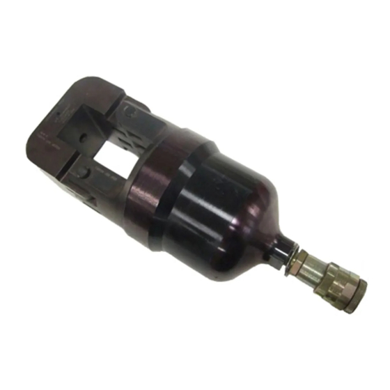
DYNA-CRIMP
Crimping Head
69051
Setscrew
Pivot
Pin
Ram
Quick-Disconnect
Coupling
Figure 1
1. INTRODUCTION
This instruction sheet provides instructions on product
application and a Maintenance and Inspection
procedure for the DYNA–CRIMP Crimping Head
69051. This tool is used to crimp:
S
AMPLI–BOND* Terminals, wire sizes 8–2
S
AWG. See Instruction Sheet 408–1758.
PLASTI–GRIP* Terminals, wire sizes 8–2
AWG. See Instruction Sheets 408–1729 and
S
408–1758.
Pre–Insulated AMPOWER* Terminals, wire
S
size 2. See Instruction Sheet 408–1758.
COPALUM* Terminals and Splices, wire sizes
8–4 (inhibitor filled) AWG. See Instruction
S
Sheet 408–2134.
TERMINYL* Terminals and Splices, wire sizes
8–2 AWG. See Instruction Sheet 408–1729.
E
2008 Tyco Electronics Corporation, Harrisburg, PA
All International Rights Reserved
TE logo and Tyco Electronics are trademarks.
*Trademark. Other products, logos, and company names used are the property of their respective owners.
DYNA-CRIMP*
Crimping Head
69051
S
Yoke
Basic instructions on the use of this crimping head
are provided in Section 2, INSTRUCTIONS. Section 3
contains a Maintenance and Inspection Procedure
required to establish and maintain a tool certification
program.
2. INSTRUCTIONS
Cylinder
Head
2.1. Attaching the Crimping Head
NOTE
i
Removable
Latch Pin
DANGER
1. Thoroughly clean coupling area of handle
Cylinder
control or hose assembly and crimping head.
2. Remove protective (dust) caps.
3. Mate both quick–disconnect couplers and
tighten collar of coupler assembly on crimping
head. See Figure 1.
Dust Cap (Ref)
CAUTION
!
NOTE
i
2.2. Die Insertion and Removal
DANGER
A. Die Insertion
1. Remove latch pin and open yoke. See Figure 2.
TOOLING ASSISTANCE CENTER 1-800-722-1111
PRODUCT INFORMATION 1-800-522-6752
Pre–Insulated AMPOWER Terminals wire sizes
4–2 AWG. See Instruction Sheet 408–1729.
If a coupling component for the hose assembly is
packaged inside the quick-disconnect coupler on
the head, it is to be used to replace the coupling
on a hose assembly not equipped with a
quick-disconnect coupler.
Avoid personal injury. Release hydraulic pressure
to hose or handle control. Disconnect electric
power unit from power supply.
Oil flow must be unobstructed between power
unit and crimping head. Ensure that all couplers
are fully mated and tightened.
If a crimping head must be removed after power
unit was in operation, pressure must be released
in the hydraulic system. When using hydraulic
power unit 69120-[ ], DISCONNECT POWER
UNIT FROM POWER SUPPLY. When using
hydraulic hand pump 314979-1, make sure to
depress pressure release lever.
Avoid personal injury. When using power unit,
exercise caution to avoid accidentally depressing
the foot switch or handle control when changing
dies.
This controlled document is subject to change.
For latest revision and Regional Customer Service,
www.tycoelectronics.com
visit our website at
Instruction Sheet
408-2450
(was IS 2450)
20 MAY 08
Rev A
1
of 4
LOC B
Advertisement
Table of Contents

Related Manuals for Tyco Electronics DYNA-CRIMP


Summary of Contents for Tyco Electronics DYNA-CRIMP
- Page 1 For latest revision and Regional Customer Service, All International Rights Reserved www.tycoelectronics.com visit our website at TE logo and Tyco Electronics are trademarks. LOC B *Trademark. Other products, logos, and company names used are the property of their respective owners.
- Page 2 Since there is a possibility of damage in shipment, CAUTION Ensure that the latch pin is fully inserted or Tyco Electronics recommends that new heads be damage may occur to the yoke, dies, or latch pin. inspected in accordance with Section 3 when received in your plant.
- Page 3 408-2450 DYNA-CRIMP Crimping Head 69051 1. Remove crimping head from handle control or Check these coupling and place in a vise. Use a suitable Areas for Cracks material to protect the finish on the head. 2. Remove the set screw (Item 7) that secures the head assembly to the cylinder.
- Page 4 408-2450 DYNA-CRIMP Crimping Head 69051 ITEM PART QTY PER DESCRIPTION NUMBER TOOL 311470-1 COUPLER, Quick-Disconnect, Cylinder Half 2-21053-5 O" RING, [1.625 O.D. x 1.375 I.D. x .125] Width 1-21107-1 RING, Back-Up 48736 PISTON 301703 SPRING, Piston Return 21061-1 SCREW, Socket Set (Cone Point) 4-40 UNC x [.125 in.] Long...
Need help?
Do you have a question about the DYNA-CRIMP and is the answer not in the manual?
Questions and answers