Table of Contents
Advertisement
Quick Links
Stationary Die
(Nest)
Anvil Die
Hold-Down Device
and Contact Locator
Front of Tool
1. INTRODUCTION
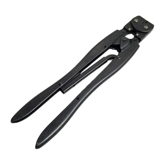
ROTA–CRIMP Crimping Tool 68321–1 (shown in
Figure 1) is used to crimp Series 75 Power Lock
Contact 53880–4 onto solid or stranded wire sizes 10,
8, or 6 AWG. Read these instructions thoroughly
before using the tool.
Dimensions in this instruction sheet are in
NOTE
millimeters [with inches in brackets]. Figures are
not drawn to scale.
i
Reasons for reissue of this instruction sheet are
provided in Section 7, REVISION SUMMARY.
2. DESCRIPTION
The FRONT of the tool, into which the contact is
inserted, can be identified by the tool part number on
the link. The tool features a stationary die (6.35 [.250]
wide F crimp nest), rotatable anvil die with three
settings, hold–down device, and contact locator. The
E
2008 Tyco Electronics Corporation, Harrisburg, PA
All International Rights Reserved
TE logo and Tyco Electronics are trademarks.
*Trademark. Other products, logos, and company names used are the property of their respective owners.
Downloaded from
Elcodis.com
electronic components distributor
ROTA-CRIMP* Crimping Tool 68321-1
Locator Pin
Indexing
Pin
Wire Size
Marking
Figure 1
TOOLING ASSISTANCE CENTER 1-800-722-1111
PRODUCT INFORMATION 1-800-522-6752
anvil must be set to the wire size being used. The
applicable wire size is stamped on the base of the
anvil die. When closed, the dies form one crimping
chamber.
The hold–down device and contact locator are
mounted on a metal strip. The metal strip must be
adjusted to accommodate the contact position during
the crimping process.
3. CRIMPING PROCEDURE
Refer to Figure 2, and strip the wire to within the
dimensions shown.
DO NOT use wires with missing or nicked
NOTE
conductor strands.
i
Series 75 Power Lock Contact
Transition
Area
Strip Length
CONTACT
WIRE SIZE (AWG)
53880-4
10, 8, 6
Figure 2
Proceed as follows:
1. Open the tool head. Make sure that the anvil die
is locked in position and that the locator pin is
visible as shown in Figure 1. It is not necessary at
this time to set the anvil die to a specific wire size.
2. Place a sample contact in the nest of the
stationary die as shown in Figure 3. The open end
of the wire barrel must be aligned in the nest.
3. Loosen the two screws securing the hold–down
device and contact locator, and position the contact
locator over the contact tongue as shown in Figure
3. Do not re–tighten the screws at this time.
The hold-down device and contact locator must
NOTE
be properly adjusted so that the contact will
remain aligned during the crimping process.
i
This controlled document is subject to change.
For latest revision and Regional Customer Service,
visit our website at www.tycoelectronics.com
Instruction Sheet
408-2681
08 SEP 08
Rev B
Wire Barrel
WIRE STRIP
LENGTH
7.95-9.53
[.313-.375]
1 of 6
LOC B
Advertisement
Table of Contents

Related Manuals for Tyco Electronics ROTA-CRIMP 68321-1


Summary of Contents for Tyco Electronics ROTA-CRIMP 68321-1
- Page 1 For latest revision and Regional Customer Service, All International Rights Reserved visit our website at www.tycoelectronics.com TE logo and Tyco Electronics are trademarks. LOC B *Trademark. Other products, logos, and company names used are the property of their respective owners.
- Page 2 For a detailed inspection requirements, refer to (wire–entry end) so that it extends from the nest Application Specification 114-6032. area between 0.76 to1.02 [.030 to .040] as shown in Figure 4. 2 of 6 Rev B Tyco Electronics Corporation Downloaded from Elcodis.com electronic components distributor...
- Page 3 2. Make certain all retaining pins are in place and secured with retaining rings. If replacements are 2. Turn both adjustment (ADJ) screws clockwise necessary, refer to Section . approximately one–half to three–quarter turn. Rev B 3 of 6 Tyco Electronics Corporation Downloaded from Elcodis.com electronic components distributor...
- Page 4 (AWG) NO-GO NO-GO 2.565-2.573 [.1010-.1013] 2.817-2.819 [.1109-.1110] 3.226-3.243 [.1270-.1272] 3.396-3.401 [.1337-.1339] 2.946-2.954 [.1160-.1163] 3.198-3.200 [.1259-.1260] 3.548-3.553 [.1397-.1399] 3.724-3.729 [.1466-.1468] 3.581-3.589 [.1410-.1413] 3.833-3.835 [.1509-.1510] 4.102-4.107 [.1615-.1617] 4.285-4.290 [.1687-.1689] Figure 9 of 6 Tyco Electronics Corporation Downloaded from Elcodis.com electronic components distributor...
- Page 5 5. In the same manner, try to insert the NO–GO parts is necessary. Parts other than those listed element into the crimping chamber. The NO–GO should be replaced by Tyco Electronics to ensure element may enter partially, but must not pass quality and reliability. Order replacement parts completely through the length of the crimping through your representative, or call 1–800–526–5142,...
- Page 6 21004-3 SCREW, Shoulder, .25 in. Dia .62 in. L 314224-1 LOCATOR, Terminal 314225-1 TERMINAL, Hold Down 2-21000-9 SCREW, Socket Head, 8-32 .75 in. L 21055-6 WASHER, Flat Figure 10 of 6 Tyco Electronics Corporation Downloaded from Elcodis.com electronic components distributor...
Need help?
Do you have a question about the ROTA-CRIMP 68321-1 and is the answer not in the manual?
Questions and answers