Table of Contents

Related Manuals for SKF GVP-S-034-3D+924


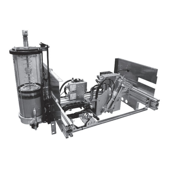
Summary of Contents for SKF GVP-S-034-3D+924
- Page 1 Installation and operation manual Grease injection lubrication system GVP-S-034-3D+924, GVP-S-034-3G+924 for RoDip-3 chains Version Date of issue October 2016 Publication number 951-130-450-S034-3 Languages Country/Countries ...
-
Page 3: Table Of Contents
6.3 PVP.3 pump ........... 16 Or an SKF Service Centre, the addresses of 6.4 Limit switch . - Page 4 EC Declaration of Incorporation in accordance with EC-Machinery Directive 2006/42/EC, Appendix II Part B The manufacturer SKF France SAS, 204, Bld Charles de Gaulle, B.P. 239 – 37540 St-Cyr-sur-Loire – FRANCE, declares herewith the con- formity of the partly completed machine...
-
Page 5: Safety Instructions
CLP regulation (EC 1272/2008), and identified with hazard picto- grams GHS01-GHS06 and GHS08. None of the products manufactured by SKF can be used in con- junction with gases, liquefied gases, pressurized gases in solution and fluids with a vapor pressure exceeding normal atmospheric pressure (1013 mbar) by more than 0.5 bar at their maximum per-... -
Page 6: Warranty And Liability
SKF and obtaining written permission. All products manufactured by SKF are not approved for use in conjunction with gases, liquefied gases, pressurized gases in solu- tion and fluids with a vapor pressure exceeding normal atmospheric pressure (1013 mbar) by more than 0,5 bar at their maximum per- missible temperature. -
Page 7: Approved Lubricants
(e.g. 'oil separation' behavior) in centralized lubrication systems. 2.5 Danger relating to lubricants You can request an overview of lubricant tests offered by SKF from our Service Center. 2.3 Approved lubricants DANGER! Centralized lubrication systems must be absolutely leak- free. -
Page 8: Design And Function
3 Design and function 3.1 Construction The grease injection system type GVP-S-034-3D et 3G contains all mechanic, hydraulic, pneumatic and electrical components required for the operation of a lubrication system for conveyor chains (RoDip-3). The main components of the system are: •... -
Page 9: Function
3.2 Function The function principle of the grease injection system for the lubrica- tion of conveyor chains is more or less the same for all systems († fig. 2). However some models differ from others by the type of lubrication points, the number of injection heads, etc. - Page 10 Fig. 3 GVP-S PVP.3 0-160 EVE2 4-20 Galets EVE1 Axes Hydropneumatic layout GVP-S-034-3D and -3G with brushing device Hydropneumatic layout GVP-S-034-3D and -3G 3 Return cylinder 4 Air flow limiter 5 Position detector A/ Pump assembly 6 (option) Pressure sensor in the lubricant injector 1 Pressure regulating valve 2 Air pressure gauge 3 PVP.3 pump...
-
Page 11: Installation Instructions
If you do not have access to this documentation, you can request it direct- ly from SKF. The lubrication system is directly installed above the conveyor chain on an especially adapted rail. It must be fitted to the rail with the two flanges (†... -
Page 12: Pneumatic Connection
(† pos. 1 fig. 7) of the system. For the product-specific electric data see the relevant documentation. If you do not have access to this docu- mentation, you can request it directly from SKF. Pneumatic outlets 1 Pressure regulating valve for PVP.3 pump... -
Page 13: Hydraulic Connection
4.3 Hydraulic connection A pump type PVP.3 with integrated reservoir is directly mounted on the system and supplies lubricant to the lubrication system. There is no hydraulic connection necessary except for the filling of the PVP.3 pump reservoir († § 6.3.1 Filling). DANGER! The maximum lubricant pressure indicated for system operation must not be exceeded. -
Page 14: Mechanical Adjustments
4.3 Mechanical adjustments The position of the lubrication system must be mechanically adjust to optimize the lubrication process. Several mechanical adjustment have to be carried out: • Position adjustment • Pick-up system adjustment 4.3.1 Position adjustment With the position setting it is possible to center the injection head of the lubrication system with the greaser of the lubrication point. - Page 15 4.3.2 Pick-up system Fig. 10 The lubrication unit has two pick-up systems for rollers and pins. Roller pick-up system DANGER! The setting of the pick-up systems has to be made only when the air supply is off. First identify the two pick-up systems and then proceed to adjustment.
-
Page 16: Transport, Delivery And Storage
5 Transport, delivery and storage 5.1 Transport SKF products are packaged in accordance with the regulations of the recipient country and in accordance with DIN ISO 9001. Our prod- ucts must be transported with care. Products must be protected against mechanical influences such as impacts. Transport packaging must be labeled with the information 'Do not drop!'. -
Page 17: Commissioning
The operating manual of the AEP3 control unit is deliv- ered with the lubrication system. If you do not have access 6.2.1 Proximity switch adjustment to this manual, you can request it from SKF. The GVP system has three sensors: • An inductive proximity switch for the pins •... -
Page 18: Pvp.3 Pump
6.3 PVP.3 pump 6.3.1 Filling The lubrication system is equipped with a pneumatic pump and a 8 kg lubricant reservoir. The reservoir is made of transparent plastic for a visual lubricant level monitoring. It is also equipped with a min. level switch. -
Page 19: Modification Of The Injector Metered Volume
6.4 Modification of the injector metered Fig. 14 volume 0,5 cm 1 cm The GVP lubrication system is delivered with a fixed metered vol- ume. It is possible to modify later this metered volume. Four differ- ent metered volumes are available: 0,33 ; 0,5 ; 0,75 or 1 cm injection. - Page 20 Fig. 17 The lubrication system GVP must be disconnected from the power supply and not under pressure when modifying the metered volume. Therefore turn off the power supply and depressurize the system. • Check the GVP unit is off and the air supply closed. •...
-
Page 21: Shutdown
Lubricants can contaminate the ground and watercours- es. Lubricants must be used and disposed of in compliance with the rules. Instructions and local regulations must be observed when handling lubricants. The system can also be taken back by SKF for disposal if the costs are covered. -
Page 22: Maintenance
Doing so invalidates all warranty claims. Only original SKF spare parts may be used. It is prohibited for the operator to make alterations to the product or to use non original spare parts and resources. Doing so invalidates all war-... -
Page 23: Failures
Table 2 gives an overview of possible malfunctions and their causes. use non original spare parts and resources. If you are unable to rectify the malfunction, please contact SKF Ser- vice Center. You must not dismantle the product or parts of the prod- DANGER! uct during the warranty period. -
Page 24: Technical Data
10. Technical data Table 3 Technical data GVP-S-034-3D and -3G system Air feed pressure 5 to 7 bar Injection volume 0,33 to 1 cm (factory setting 1 cm Operating temperature 5 to 45 °C Lubricant grease NLGI grade 2 Pneumatically driven pump (PVP.3) Air feed pressure 8 bar max. - Page 26 Important information on product usage SKF and Lincoln lubrication systems or their components are not approved for use with gases, liquefied gases, pressurized gases in solution and fluids with a vapor pressure exceeding normal atmospheric pressure (1 013 mbar) by more than 0,5 bar at their maximum permissible temperature.
Need help?
Do you have a question about the GVP-S-034-3D+924 and is the answer not in the manual?
Questions and answers