Table of Contents

Related Manuals for SKF LINCOLN GVP-S-030-6


Summary of Contents for SKF LINCOLN GVP-S-030-6
- Page 1 Operating Instructions Grease lubrication unit GVP GVP-S-030-6 Date of issue: 30-01-2022 Document No.: 951-130-450-01 Version : Read manual prior to installation or use of this product. Keep manual nearby for future reference.
- Page 2 Appendix II Part 1 B SKF France SAS, 204, bld Charles de Gaulle, 37540 St-Cyr-sur-Loire, France, hereby declares at its sole responsibility that the partly completed machinery conforms to the essential health and safety requirements of the Machinery Directive 2006/42/EC, Annex I, marked in the Annex to the EC Declaration of Incorporation as applicable and fulfilled at the time of placing on the market.
-
Page 3: Imprint
Heinrich-Hertz-Straße 2-8 69190 Walldorf Germany Tel. +49 (0)6227 33-0 Fax +49 (0)6227 33-259 Or an SKF Service Center, the addresses of which are given on our website: www.skf.com/lubrication Training courses In order to provide a maximum of safety and economic viability, SKF carries out detailed training courses. -
Page 4: Table Of Contents
6.4.2 Pick-up system ............17 Table of contents 6.5 Proximity switch ..............17 6.5.1 Metal support ............17 Imprint ....................3 6.5.2 Sensing distance of the proximity switch ....18 6.6 External connections ............19 Manufacturer ..................3 6.6.1 Pneumatic connection ..........19 6.6.2 Hydraulic connection .......... -
Page 5: Safety Alerts, Visual Presentation, And Layout
Safety alerts, visual presentation, and layout While reading these instructions, you will encounter various symbols, illustrations, and text layouts intended to help you navigate and understand the instructions. Their meaning is explained below. Safety alerts: Activities that present specific hazards (to life and limb or possible damage to property) are indicated by safety alerts. -
Page 6: Safety Instructions
Unauthorized modifications and changes are therefore prohibited. Only Specialist in electrics original SKF spare parts and SKF accessories may be used. Person with appropriate professional education, knowledge and • Any unclear points regarding proper condition or correct experience to detect and avoid the hazards that may arise from assembly/operation must be clarified. -
Page 7: Referenced Documents
1.12 Note on Pressure Equipment 1.6 Referenced documents Directive In addition to this manual, the following documents must be observed by the respective target group: Due to its performance characteristics, the product does not • Company instructions and approval rules reach the limit values defined in Article 4, Paragraph 1, If applicable: Subparagraph (a) (ii) and is excluded from the scope of Pressure... -
Page 8: Lubricants
Solid lubricants may only be used after prior consultation with make the selection in consultation with the supplier of the SKF. When solid lubricants are used in lubrication systems, the lubricant. If you have no or little experience in selecting following rules generally apply: lubricants for lubrication systems, please contact us. -
Page 9: Overview, Functional Description
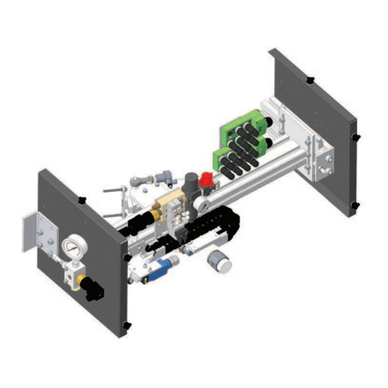
3.2 Version 3. Overview, functional In general two units are necessary to lubricate chains of an description industrial conveyor. Each unit is located on one side. It is important to pay attention to the GVP unit model in comparison 3.1 Construction to the chain running direction. - Page 10 Fig. 1 GVP-S-030-6...
-
Page 11: Function
GVP-S-030-6 system 3.3 Function The lubrication system is dedicated to the lubrication of the The function principle of the grease injection system for the rollers of a conveyor chain. It features one injection head and lubrication of conveyor chains is more or less the same for all one pick-up system. - Page 12 Fig. 2 Grease 0-160 BA R 4-20 G+I, Schematic diagram B - Air treatment unit D - Control assembly 1 Sectional valve 1 Solenoid valve 5/2, pick-up and return 2 Regulator-filter 2 Solenoid valve 5/2, injection control 3 Pressure switch 4 Pressure gauge E - Roller proximity switch C - Injection carriage...
-
Page 13: Technical Data
4. Technical data Table 2 Technical data GVP-S-030-6 lubrication unit GVP unit Air feed pressure 5 to 7 bar Lubricant inlet pressure max. 120 to 250 bar Injection volume 0,33 ; 0,5 ; 0,75 and 1 cm (factory setting 1 cm Operating temperature 5 to 45 °C Lubricant... -
Page 14: Delivery, Returns, Storage
5.4 Storage temperature range 5. Delivery, returns, storage For parts not filled with lubricant, the permitted storage 5.1 Delivery temperature is the same as the permitted ambient temperature range (see “Technical data”). After receipt of the shipment, it must be inspected for any 5.5 Storage conditions for products filled shipping damage and for completeness according to the shipping documents. -
Page 15: Assembly
6.2.2 Positioning 6. Assembly The lubrication unit should be installed on the conveyor chain < return strand. When selecting the set-up location observe the WARNING following main points: Chain in motion All installation, setting, maintenance and repair • In advance the rail section, where the GVP unit will be works on the lubrication system must be carried installed. -
Page 16: Mechanical Adjustments
Fig. 5 ±0,5 1,4° 1,4° ±0,5 Support rail 1 SKF delivery Fig. 6 6.4 Mechanical adjustments The position of the lubrication unit must be mechanically adjusted to optimize the lubrication process. Several mechanical adjustments have to be carried out: • Position setting •... -
Page 17: Pick-Up System
NOTE For the product-specific technical data the proximity switch, see the relevant documentation. If you do not have access to this documentation, you can request it directly from SKF. WARNING The proximity switches may be connected only by properly qualified and instructed personnel. -
Page 18: Sensing Distance Of The Proximity Switch
If the detector is suitable for flush mounting is metal, then no Fig. 10 side clearance is required. But if it is not suitable for flush Sensor, flush mounting in metal mounting in metal, then a side clearance is required. 6.5.2 Sensing distance of the proximity switch (→... -
Page 19: External Connections
6.6.1.1 Air network security 6.6 External connections Operator must be able to shut down and/or depressurize air 6.6.1 Pneumatic connection supply network of GVP unit. He must install upwards the unit: The lubrication unit must be connected to the compressed air •... -
Page 20: Electrical Connection
(e.g. DIN, VDE) must be scrupulously respected. If systems are improperly connected, substantial material or personal damage my be the consequence. NOTE For the product-specific electric data see the relevant documentation. If you do not have access to this documentation, you can request it directly from SKF. -
Page 21: First Start-Up
during inspection, appropriate corrective measures must be 7. First start-up taken before commissioning. 7.1 Inspections prior to commissioning The operator must carry out the following inspections before commissioning the lubrication system. If a problem appears Table 3 Prior inspections Monitoring Chapter GVP unit ... -
Page 22: Preparation To Commissioning
Test failed 7.2 Preparation to commissioning In the case test is failed, find out failure reason. 7.2.1 Sensor adjustment 1. Look for the failure possible reason at GVP unit (→ chapter 10. ) 2. Check lubrication cycle parameters in control unit. 1. - Page 23 reversible metering stops (→ fig. 16), one is mounted in the Fig. 16 injector, the other delivered separately. 0,5 cm 1 cm NOTE A number of washers screwed on the injector indicate the metered volume of the GVP system (→ fig. 17). Therefore change the number of washers when modifying the metered volume.
- Page 24 Fig. 21 CAUTION The lubrication system GVP must be disconnected from the power supply and not under pressure when modifying the metered volume. Therefore turn off the power supply and depressurize the system. 1. Check the GVP unit is off and the air supply closed. 2.
-
Page 25: Commissioning
7.5 Commissioning 1. Switch on the control unit of the GVP unit 2. Close air supply to GVP unit 3. Close grease supply to GVP unit GVP lubrication unit is ready for operation. Lubrication cycles are launched and managed by the operator. NOTE Chain max. -
Page 26: Operation
8. Operation During GVP unit normal operation, lubrication cycles are set, launched and controlled by the operator. NOTE Chain max. speed During lubrication maximal chain max. speed must not exceed 9 m/min. < CAUTION Chain max. speed Exceeding the maximal chain speed during lubrication process can cause serious material damages on GISB unit and on the chain itself. -
Page 27: Maintenance And Repair
All other work relating to installation, maintenance, and repair must only be carried out by SKF Service. Only original SKF spare parts may be used. It is prohibited for the operator to make alterations to the product or to use non original spare parts and resources. - Page 28 Check pick-up system (no loose part) CAUTION Maintenance delay Maintenance delays are given in accordance with experience acquired by SKF. They do not necessarily meet the concrete application conditions. The operator must therefore adjust maintenance delays in accordance with his application without missing given...
-
Page 29: Faults, Causes, And Remedies
GVP unit. maintenance, and repair must only be carried out by SKF Service. < Only original SKF spare parts may be used. It is WARNING prohibited for the operator to make alterations to Pressure... - Page 30 Table 5 Failure analysis and remedy Problems Possible cause Remedy • Check the pneumatic pressure and adjust if necessary Lubricant leak on pin nipples Incorrect head-nipple alignment • Check the alignment and make adjustments as necessary Deformed or damaged nipples on •...
-
Page 31: Shutdown, Disposal
All valid guidelines and legislation on the disposal of contaminated equipment must be observed when shutting down the product for the final time. The product can also be taken back by SKF for disposal if the costs are covered. Components can be recycled. <... -
Page 32: Spare Parts
12. Spare parts NOTE Only original SKF spare parts may be used. It is prohibited for the operator to make alterations to the product or to use non original spare parts and resources. Table 6 Spare part list GVP-S-030-6 Position... - Page 33 Fig. 23 Spare parts...
- Page 34 ® SKF is a registered trademark of the SKF Group. ™ eLube is a trademark of the SKF Group. © SKF Group 2022 Reprint or reproduction of the contents of this information - even in part - is permitted only with SKF's prior written consent.
Need help?
Do you have a question about the LINCOLN GVP-S-030-6 and is the answer not in the manual?
Questions and answers