SKF KFG Assembly Instructions Manual
Hide thumbs
Also See for KFG:
- Assembly instructions manual (108 pages) ,
- Assembly instructions manual (111 pages) ,
- Assembly instructions manual (86 pages)

Related Manuals for SKF KFG


Summary of Contents for SKF KFG
- Page 1 KFG; KFGS; KFGC (CAN bus) Assembly instructions acc. to EC Dir. 2006/42/EC for partly completed machinery with associated operating instructions for industrial use Version 02...
- Page 2 Page 2 Notes Service Masthead © SKF Lubrication Systems Germany GmbH If you have technical questions, please contact These original assembly instructions with as- This documentation is protected by copyright. the following addresses: sociated operating instructions according to EC SKF Lubrication Systems Germany GmbH re-...
- Page 3 CAN bus system 4.5.6.5 CAN bus system coniguration without Settings for single-line lubrication Pump elements 4.5.3.5 Timer operation without system connection to CAN bus system 4.3.1 KFG/KFGS pump elements monitoring 4.3.2 KFGC (CAN bus) pump elements Fill level control 4.5.3.6 Timer operation with system 4.3.3...
- Page 4 1. Safety instructions 6.1.1 Pump element 7. Functional description in single-line systems 65 6.1.2 Pressure regulating valve Functional description of single-line systems with KFG pump unit 65 2. Lubricants 6.2. Functional description in progressive systems with KFGS pump unit 7.1.1 Pump element 6.3.
- Page 5 15.1.7 Malfunctions on pump unit 11.5 Change access code in progressive system 11.6 Programming ranges 15.1.8 Malfunctions 11.7 Display ranges on KFG/KFGS pump units 15.2 Operational malfunctions on 12. KFGS operating modes KFGC (CAN bus) 12.1 Timer operation 15.2.1 Pump malfunctions 12.2 Counter operation 15.2.2 Faults detected by control unit...
- Page 6 Page 6 EC Declaration of Incorporation according to Machinery Directive 2006/42/EC, Annex II Part 1 B The manufacturer SKF Lubrication Systems Germany GmbH ,Plant Hockenheim, 2. Industriestraße 4, DE - 68766 Hockenheim hereby declares that the partly completed machinery: Designation:...
-
Page 7: Explanation Of Symbols And Signs
Explanation of symbols Page 7 Explanation of symbols and signs You will find these symbols, which warn of Instructions placed directly on the machines/ specific dangers to persons, material assets, or grease lubrication pump units, such as: the environment, next to all safety instructions You are responsible! Arrow indicators Labels for luid connections... - Page 8 Page 8 Assembly instructions Assembly instructions in accordance with Machinery Directive 2006/42/EC, Annex VI The assembly instructions fulfill the Machinery Directive indicated above with regard to “partly completed machinery.” Partly completed ma- chinery, which includes the product described herein, is only intended to be incorporated into or assembled with other machinery or other partly completed machinery or equipment, thereby forming machinery to which the...
-
Page 9: Safety Instructions
Note that the assembly instructions Pump units of SKF's KFG, KFGS and KFGC scribed product is incorporated. Such persons form part of the product and must... - Page 10 Page 10 Assembly instructions 1.3 Electric shock hazard 1.4 System pressure hazard Max. particle size 40 μm Max. particle density 10mg/m³ Electrical connections for the described product Lubrication systems are pressurized Pressure dew point 7°C may only be established by qualified and during operation.
- Page 11 Only the pump models tested and monitor must be supplied by an intrinsi- is limited. It must therefore undergo a approved by SKF Lubrication Systems cally safe circuit, e.g., through the installa- function and leak test at regular intervals. Germany GmbH in accordance with...
- Page 12 2. Lubricants 2.1 General information 2.2 Selection of lubricants All products from SKF Lubrication No products manufactured by SKF Lubrication Observe the instructions from the Systems Germany GmbH may be used Systems Germany GmbH are approved for use machine manufacturer regarding the...
- Page 13 You can request an overview of the lubricant accidental mixing of lubricants. It is important to note that lubricants are envi- tests offered by SKF Lubrication Systems The product described here can be operated ronmentally hazardous, flammable substances Germany GmbH from the company's Service...
- Page 14 Page 14 Assembly instructions for information regarding transport, storage, Warning! processing, and environmental hazards of the Follow the safety instructions on the lubricant that will be used. lubricant's safety data sheet. The safety data sheet for a lubricant can be re- quested from the lubricant manufacturer.
- Page 15 Assembly instructions Page 15 3. Overview Components Components Item Description Chapter Assembly holes 4.2.1 2 Lubricant reservoir 4.2.2 KFGS 3 Pump elements 4.3. 4 Pressure regulating valve 4.3.5 5 Conical head nipple 4.3.5 6 Electrical connection 7 General control unit Operating CAN bus display instructions...
- Page 16 The unit is mounted in a vertical position. adequate distance from sources of heat. of the KFG or KFGS series to operate up to three independent zones. Any assembly holes must be made according Maintain safety clearances and comply to the diagram on the following page.
- Page 17 Warning! The torque of the fastening screws Warning! depends on the customer’s installation. Do not tilt the KFG (S) (C) grease Make sure that torque is adequate lubrication pump unit! when installing the pump unit!
-
Page 18: Assembly Holes
Page 18 Assembly instructions 4.2.1 Assembly holes 4.2.2 Mounting dimensions Minimum mounting clearance ± E = 20 mm Ø 9,0 1) KFGS-_5...- 12 VDC or 24 VDC =pump unit Mounting dimensions with control unit and supply volt- age of 12 or 24 VDC Description Reservoir capacity... - Page 19 4.3.1 KFG/KFGS pump elements 3/2 directional control valves can be employed ing valve (2) (or lubrication line (3)) on an KFG and KFGS pump units can be equipped so that lubricant connections can also return already mounted pump element (1).
- Page 20 Screw plug Marking grooves, see table, column for number of grooves Pipe connector Pump element with KFG pump element with constant delivery rate, without KFG pump element with constant delivery rate, without pressure regulating valve pressure regulating valve pressure regulating valve...
- Page 21 Assembly instructions Page 21 4.3.5 Pressure regulating valve Spare parts Pressure regulating valve without A pressure regulating valve (1) protects the lubricant nipple entire lubrication system against excessive sy- Pipe Ø Cracking pressure Order number stem pressure. It is mounted directly on the [mm] [bar] pump element (2).
-
Page 22: Lubricant Illing
Page 22 Assembly instructions 4.4 Instructions on lubricant illing 4.4.1 Lubricant illing Only ill using clean lubricant and an Lubricant illing is performed using a appropriate illing device. Contaminated DIN 71412-AM10x1 conical head nipple (1) lubricants can result in severe system and a conventional grease press. malfunction. The conical head nipple can be twisted onto the position (2), for example to gain better The lubricant reservoir is illed in different access. - Page 23 Assembly instructions Page 23 4.4.2 Filler coupling 4.4.3 Filling cylinder 4.4.4 Filling cover The pump unit can also be illed through one A special design for the pump units is illed As an alternative or addition to a conical head of the lubricant outlets using a illing cylinder nipple (1), the unit can also be equipped with a with lubricant through a special hinged lid or a iller socket (part No. 995-000-705) (2) to ill (1).
-
Page 24: General Conditions For Electrical Connections
Page 24 Assembly instructions 4.5 Electrical connection 4.5.1 General conditions for electrical connections KFG; KFGS; KFGC, general conditions for electrical connections Warning! Nominal Power Power Pump Max. Compare the operating voltage with the speciications on the rating plate. voltage consumption consumption starting current pre-connected fuse (load-dependent) (max.) - Page 25 4.5.2.1 Power supply 12/24 VDC 4.5.2.2 Power supply 90-264 VAC 4.5.2 KFG series The KFG pump unit is available in the voltage designs 12 VDC or 24 VDC and in 90-264 VAC and 120-370 VDC designs. The electrical voltage connection is established through a 4-pin cable socket according to DIN EN 175301-803.
-
Page 26: External Control
Page 26 Assembly instructions 4.5.2.3 External control Functional description Note The W1 fill level switch is designed as a rocker The external control units listed in switch and is integrated in the bottom of the Chapter 17 are designed to control the reservoir. - Page 27 Assembly instructions Page 27 4.5.2.4 Fill level monitoring Type: W2 for grease NLGI Grade ≤ 1 Cable connection - see table with cable colors Technical data Fill level ..Switch opens at min. monitoring fill level, fault Function Cable socket ) per...
- Page 28 (max. 24 VDC) for NLGI Grade 2 greases W1_smooth connection same as The following functions are integrated into the KFG pump unit with signal smoothing: W2 control (W1_smooth => isolation of Ability to isolate supply voltage supply voltage potentials between...
- Page 29 Assembly instructions Page 29 Connection diagram for loating W1 control Connection diagram for energized W1 con- with signal smoothing for NLGI Grade 2 trol with signal smoothing for NLGI Grade 2 greases (W1G = standard design) greases com nc W1G connector pin assignment (pump unit) Connector pin assignment (pump unit) Description Description...
- Page 30 Page 30 Assembly instructions 4.5.2.5 Pressure relief valve with integrated pressure regulating valve (for single-line systems with VR distributors) Technical data Pressure relief valve 24 VDC Input voltage ... . . 24 VDC Rated output .
- Page 31 Assembly instructions Page 31 4.5.3 KFGS series 4.5.3.1 Power supply 12/24 VDC with integrated control The KFGS pump unit is available in the voltage Connector pin assignment designs 12V or 24VDC and in 90-264 VAC and Color code Conductor coloring 120-370 VDC designs.
-
Page 32: Settings For Progressive Lubrication
Page 32 Assembly instructions Settings for progressive lubrication 4.5.3.2 Connectivity for counter operation without system monitoring KFGS... The interval depends on the number of pulses. The pump cycle time is time-dependent. Accessories Programming: Description Order No. MK-machine contact cPA, tCO, COP = OFF - see Chapter 6 Cable harness, in corrugated pipe, with pump-side socket 8 m length... - Page 33 Assembly instructions Page 33 4.5.3.3 Connectivity for counter operation 4.5.3.4 Connectivity for counter operation Control using machine pulses without system monitoring with system monitoring (progressive (Counter mode = load-dependent lubrication) centralized lubrication systems) The duration of the interval time is determined Programming: cPA, tCO, COP = OFF Programming: cPA, tCO, COP = CS by a pulse generator that sends pulses to the...
- Page 34 Page 34 Assembly instructions Settings for single-line lubrication 4.5.3.5 Connectivity for timer operation 4.5.3.6 Connectivity for timer operation Timer mode without system monitoring with system monitoring In timer mode, the interval time is determined by a time value. It is conigured by entering a (single-line centralized lubrication system) time value in hours. The pump cycle time is conigured using a time Programming: tPA, tCO, COP = OFF Programming: tPA, tCO, COP = PS...
- Page 35 No. 1-1730, with a piston detector and fault signal. "Electric Plug-and-Socket Connectors." A T connector with a special cable KFG...DC adapter is required for this. You can ind this, along with an illus- tration of the connection, under Accessories, Chapter 17.
- Page 36 Page 36 Assembly instructions 4.5.3.8 12/24 VDC connections for 4.5.3.9 Connectivity for timer operation 4.5.3.10 Connectivity for timer operation system monitoring using an without system monitoring with system monitoring (and ill level control) (and ill level control) M12x1 circular plug socket Programming: tPA, tCO, COP = OFF Programming: tPA, tCO, COP = CS or PS 24 VDC...
- Page 37 Assembly instructions Page 37 4.5.4.1 Pressure relief valve with integrated pressure regulating valve (for single-line systems with VR distributors) Technical data Pressure relief valve 24 VDC Input voltage ... . . 24 VDC Rated output .
-
Page 38: Code Description
Page 38 Assembly instructions 4.5.5 KFGS 90-264 VAC series with 4.5.5.1 Power supply 90-264 VAC integrated control unit You can ind technical data and the The electrical connection is established via a plug-in connector per DIN EN 17530-803 for order number of the M12x1 the power supply (on the front of the unit) and circular connector (mating part for a 4-pin M12x1 plug-in connector per circular plug socket) required by the... - Page 39 Assembly instructions Page 39 4.5.5.2 Connections for system monitoring 4.5.5.3 Connectivity for timer operation 4.5.5.4 Connectivity for timer operation with system monitoring (and ill level control) without system monitoring (and ill level control) Programming: tPA, tCO, COP = OFF Programming: tPA, tCO, COP = CS or PS 24 VDC 24 VDC + Socket connection per...
- Page 40 Page 40 Assembly instructions 4.5.6 KFGC series 4.5.6.1 Power supply 12/24 VDC The KFGC (CAN bus) pump unit is available in Connector pin assignment for power supply the voltage designs 12 VDC and 24 VDC. Color code Function In this version, the electrical connection is Brown 31 M established via a 7-pin plug-in connection on...
- Page 41 Assembly instructions Page 41 Accessories for reversing valve/piston detector Description Order No. Cable harness with socket approx. 2 m 997-000-734 Connection for reversing valve/piston detector CAN bus connection, plug type DEUTSCH DT04-3P-L012 (max. 6 connections) Connector pin assignment for CAN bus Connector pin assignment for reversing valve/piston detector Color code Function...
- Page 42 Page 42 Assembly instructions 4.5.6.2 Connectivity Example of connecting four reversing valves and four piston detectors on devices with the Assignment of Assignment of Assignment of round 7-pin plug CAN bus plug M12x1 4-pin round plug maximum equipment level (6x M12x1 circular connectors) for operating a progressive feeder system, distributed in four lubrication zones –...
- Page 43 Assembly instructions Page 43 Example of connecting a cycle switch or machine contact and a reversing valve to a device with minimum equipment level (without Assignment of CAN bus plug M12x1 circular connectors) for operating a Assignment of 7-pin circular connector progressive feeder system, multiple zones KFGS...-...B...
- Page 44 Using this valve, especially in DCV5-4+924 5/4 directional control valve is municating with the control unit over the CAN combination with the KFG CAN bus pump unit, electrically actuated with 24 VDC. network using the SAE J1939 communication protocol.
- Page 45 Assembly instructions Page 45 4.6 Fill level control for pump unit 4.7 Progressive system ventilation 4.8 Single-line system ventilation Fill pump with lubricant. Fill pump with lubricant. Visual Remove main lines (pressure relief valve as Remove main lines on unit. The transparent lubricant reservoir allows for visual ill level control. This must be performed Allow pump to run until lubricant without...
- Page 46 Page 46 4.9 Note on the rating plate Rating plates on KFG and KFGS pump units provide important key data such as designa- tion and material description (or customer number). To avoid loss of this data in case the rating plate becomes illegible, these characteristics should be entered in the following table.
- Page 47 Page 47 Original operating instructions KFG; KFGS; KFGC (CAN bus) acc. to 98/37/EC, Annex II B for industrial use for partly completed machinery Operating instructions associated with assembly instructions according to EC Dir. 2006/42/EC for partly completed machinery...
- Page 48 The safety instructions listed in Chapter 1, Caused by the installation of non-original "Safety instructions," of the assembly instruc- SKF components or SKF spare parts tions also apply without restrictions to these Caused by inappropriate usage Resulting from improper assembly, conigu- operating instructions.
-
Page 49: Transport, Delivery, And Storage
3. Transport, delivery, and storage Page 49 3. Transport, delivery, and storage SKF Lubrication Systems Germany GmbH 3.1 Lubrication units 3.3 General notes products are packaged in accordance with standard commercial practice according to the Ambient conditions: dry and dust-free... - Page 50 Information/instruc- contained in this chapter. hered to when dismantling and dispos- tions about assembling the KFG (S) (C) grease ing of the multiline pump unit. lubrication pump units beyond the scope of the The product can also be returned to...
- Page 51 An IrDA inter- face is integrated into this, which can optionally Pump units of the KFG, KFGS and KFGC series Pump units of the KFG and KFGS series are be used to program the pump.
- Page 52 5. Design 5.3 KFG pump units 5.4 KFGS pump units Pump units of the KFG series are reservoir Pump units of the KFGS series are reservoir pump units without an integrated control unit. pump units with an integrated control unit.
- Page 53 5. Design Page 53 5.5 KFGC (CAN bus) Important system events such as a low ill Pump units of the KFGC (CAN bus) series are Aside from valve control, the outputs can also be conigured as digital outputs for other pump units from the KFGS series with an level in the lubricant reservoir are saved by integrated CAN bus control unit.
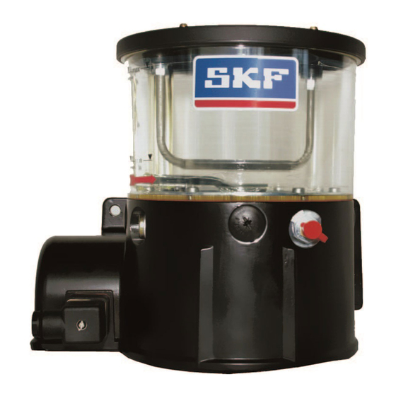
- Page 54 Page 54 5. Design 5.6 Images of pump units KFG pump unit without integrated control unit, KFGS pump unit with integrated control unit and KFGC (CAN bus) pump unit with with 2 kg lubricant reservoir 2 kg lubricant reservoir 6 kg lubricant reservoir...
- Page 55 There, the lubricant is distributed according to the volume required Layout of pump elements Example of progressive system with KFG pump unit by the lubrication point being supplied. In progressive systems with a master feeder Progressive system with KFG pump unit and secondary feeder, the lubricant coming 6.1.2 Pressure regulating valve...
- Page 56 6.2. Functional description in progressive systems with KFGS pump unit The general functional description for progres- sive systems with a KFG pump unit also applies for the design with KFGS pump control. The control unit integrated into the pump housing allows the following additional con- iguration, monitoring and connectivity options: I nterval time and pump cycle time can...
- Page 57 6. Functional description in progressive systems Page 57 6.3 Functional description of progressive When CAN commands are used for control, 6.3.1 Explanations of the lubrication pro- system with KFGC (CAN bus) pump unit valve opening must be ensured by selecting cess and lubrication cycle the appropriate contact and interval times or The general functional description for pro-...
- Page 58 Page 58 6. Functional description in progressive systems Pump cycle time Interval time Block operation, pump delay time The pump cycle time is the time during which During an interval time, also called interval for and waiting time the pump delivers lubricant. When multiple short, the pump is idle or, if multiple lubrica- On systems with piston detector monitoring, lubrication zones are used, one of the zone...
- Page 59 6. Functional description in progressive systems Page 59 6.3.2 Modes of operation Timer mode In timer mode, the interval time for each lubri- When multiple lubrication zones are used, The lubrication process can be controlled cation zone is determined by a time value. It is multiple zone valves may be addressed at the conigured by entering a time value in minutes either automatically, semi-automatically or...
- Page 60 Page 60 6. Functional description in progressive systems 6.3.2.2 Semi-automatic control unit 6.3.2.3 Control via CAN commands In this operating mode, every lubrication cycle The pump cycle time for each zone is based on In this operating mode, both the pump motor time or pulses and is conigured by entering must be started by a CAN START command.
- Page 61 6. Functional description in progressive systems Page 61 6.3.3 Monitoring functions 6.3.3.1 System monitoring 6.3.3.2 Fill level monitoring The following functions are available for moni- This function includes the following monitoring Depending on the lubricant, either mechanical toring the lubrication system: functions: or capacitive sensors are used to monitor the ill level in the lubricant reservoir. In the stan-...
- Page 62 Page 62 6. Functional description in progressive systems 6.3.3.3 Monitoring lubrication cycle via 6.3.3.4 Monitoring signal cables for cable piston detector breakage and monitoring valves and piston detectors If the speciied number of piston detector Every signal input conigured for connecting a The progressive feeders installed on the lubri- cation system are supplied with lubricant sev- pulses is not reached during the pump cycle, piston detector to the control unit is constantly eral times during the pump cycle.
- Page 63 6. Functional description in progressive systems Page 63 6.3.3.5 Monitoring switching outputs for 6.3.3.6 Monitoring power consumption of short circuits the pump motor The signal inputs can be linked to the outputs. The control unit is capable of detecting short The power consumption of the pump motor This allows indirect monitoring of whether circuit faults on the outputs.
- Page 64 Page 64 6. Functional description in progressive systems 6.3.5 Conigurable parameters 6.3.3.7 Monitoring unit temperature 6.3.4 Display and documentation functions The printed circuit board of the LC-CAN 5000 During system operation, current operational The control unit contains 16 pre-set sets of control unit contains a temperature sensor.
- Page 65 (prelubrication or relubrication distribu- tors). After metering is complete, the pump 7.1.3 Pressure relief valve Single-line system with KFG pump unit unit is cutoff by a pressure switch and the 1 KFG unit pressure relief valve is switched. After the main...
- Page 66 7.2 Functional description of single-line system with KFGS pump unit The general functional description for single- line systems with a KFG pump unit also applies for the design with KFGS pump control. The control unit integrated into the pump housing allows the following additional con- iguration, monitoring and connectivity options: Interval time and pump cycle time can be...
- Page 67 The general functional description for single- create a single-line system with up to four divided into up to four individually controllable line systems with a KFG pump unit also applies lubrication zones. The system can be equipped lubrication zones. This is performed using for the design with CAN bus pump control.
- Page 68 Page 68 7. Functional description in single-line systems 7.3.3 Control unit Pump cycle time on systems without Pump cycle time and pump delay time on pressure build-up monitoring systems with pressure build-up Explanations of the lubrication process During the pump cycle time, the system monitoring pressure required for lubrication is built up in The pressure switch monitors whether the...
- Page 69 7. Functional description in single-line systems Page 69 Interval time 7.3.3.1 Modes of operation Timer mode During an interval time, also called interval for In timer mode, the interval time for each lubri- short, the pump is idle or, if multiple lubrica- The lubrication process can be controlled cation zone is determined by a time value.
- Page 70 Page 70 7. Functional description in single-line systems In this case, the control unit opens the valves the preceding section. 7.3.3.3 Control via CAN commands in a carefully coordinated sequence so that The pump cycle time for each zone is time- dependent and is conigured by entering a only one valve is activated at a time, while still In this operating mode, both the pump mo-...
- Page 71 7. Functional description in single-line systems Page 71 7.3.4 Monitoring functions 7.3.4.1 Fill level monitoring 7.3.4.2 Pressure build-up monitoring (single-line systems) The following functions are available for moni- Depending on the unit design, either mechani- toring the lubrication system: cal or capacitive sensors are used to monitor The pressure switch monitors whether the re- the ill level in the lubricant reservoir. On units quired pressure buildup occurs in the lubrica-...
- Page 72 Page 72 7. Functional description in single-line systems 7.3.4.3 Pressure reduction monitoring 7.3.4.4 Monitoring signal cables for cable 7.3.4.5 Monitoring outputs for short circuit (single-line systems) breakage and monitoring valves and pres- sure switches The control unit is capable of detecting short The pressure reduction in the lubrication line circuit faults on the outputs.
- Page 73 7. Functional description in single-line systems Page 73 7.3.6 Conigurable parameters 7.3.5 Display and documentation functions During system operation, current operational The control unit contains 16 sets of param- data (status data) is stored in the FRAM and eter data. A parameter set contains all the can be read at any time.
- Page 74 Page 74 8. Commissioning 8. Commissioning General commissioning The product described here functions auto- Warning! matically. The lubricant transport in the lubri- Different lubricants cannot be mixed, Before the product is commissioned, all elec- cation lines should, however, be subjected to as mixing may result in damage and trical connections must be inspected.
- Page 75 9. Display and control unit Page 75 9. Display and control elements of control screen 9.1 KFGS series Display and control elements of the KFGS control screen Symbol Description Function The display and control unit is protected from Three-digit LED display Values and operating status water splashes and mechanical damage by a transparent plastic cover.
- Page 76 Page 76 9. Display and control unit 9.1.1 Three-digit LED display Three-digit LED display Display Meaning Statement Control function The display is off in normal mode. It can be activated by briely pressing one of the two = TIMER The control unit is functioning Part of lubrication cycle; entry = PAUSE as a timer and is currently in and display value in hours.
- Page 77 9. Display and control unit Page 77 Continuation of "Three-digit LED display" table Display Meaning Statement Control function The system pressure is moni- Pressure Switch Pressure switch monitoring is Pressure switch active. tored by the pressure switch during the pump cycle (single-line systems) Low Level fault: fill The minimum fill level has been...
- Page 78 Page 78 9. Display and control unit 9.1.2 LED display LED display LED lights up = display mode LED flashes = programming mode Operating voltage is present on pump unit Value for PAUSE can be changed. and control unit, system is currently in oper- ating status PAUSE Operating voltage is present on pump unit Value for CONTACT can be changed.
-
Page 79: Pushbutton Operation
9. Display and control unit Page 79 9.1.3 Pushbutton operation Pushbutton operation Function Pressing during PAUSE triggers an interim lubrication. Fault notifications are acknowledged and deleted. Switch on the display in display mode Call up next parameter in programming mode Increase displayed value by 1 Switch on the display in display mode Call up last parameter in programming mode... - Page 80 Page 80 9. Display and control unit 9.2 KFGC series (CAN bus) Display and control elements of the KFGC (CAN bus) control screen Symbol LED color Description Function The display and control screen is protected Green POWER LED Lights up when operating voltage pres- from water splashes and mechanical dam- ent.
- Page 81 9. Display and control unit Page 81 Continuation of "Display and control elements of the KFGC (CAN bus) control screen" table Symbol Description Function IrDA interface Infrared service interface Read stored status data and fault notifications Configure the control unit via PC ...
- Page 82 Page 82 10. KFGS display mode 10. KFGS display mode 10.1 KFGS series Display mode Display mode can be identiied by the lit-up Step Display LED displays. The display does not lash. It is The current operating status is shown Example: Timer operation pause used to query the current settings and operat- Press briefly ing parameters.
- Page 83 10. KFGS display mode Page 83 Continuation of "Display mode" table Step Display Monitoring switched off Monitoring via Monitoring via (factory setting) piston detector Pressure switch Display operating hours 10/11 Example: 1st part of 2nd part of total value total value Total value: 00533.8 h Write down.
- Page 84 Page 84 11. KFGS programming 11. KFGS programming The working/interval times can be repro- Change lubrication interval times grammed to adapt the lubrication intervals and the resulting lubricant quantities to speciic Step Display Display flashes requirements. (000 = factory setting) Press for more than 2 s 11.1 Start programming mode Programming mode can be identiied by Automatic display of first...
- Page 85 11. KFGS programming Page 85 Continuation of "Change lubrication interval times" table Step Display Set new value Press briefly (confirm new value) Changes are written to memory, the values are activated and Press for more than 2 s the display clears...
- Page 86 Page 86 11. KFGS programming 11.3 Conigure system monitoring Configure system monitoring Step Display System monitoring can be changed to activate Display flashes or deactivate the monitoring functions for (000 = factory setting) lubrication. Press for more than 2 s When system monitoring is active, you can se- Automatic display of first parameter: "pause in timer operation"...
-
Page 87: Change Operating Modes
11. KFGS programming Page 87 11.4 Change operating modes Change operating mode Step Display A change of operation mode means changing to Display flashes timer operation, counter operation or special ap- (000 = factory setting) plications. Press for more than 2 s Please refer to Chapter 12 for further information. - Page 88 Press briefly (321 = factory default setting) In this case, the pump unit must be (confirm code) sent to the dealer or authorized SKF branch ofice. Display flashes Press briefly (confirm key) (000 = factory setting)
-
Page 89: Programming Ranges
Fault hours 0.1 h to 99999.9 h Pump cycle time 0.1 min to 99.9 min Pulses 1 to 999 Operating hours 0.1 h to 99999.9 h 1) For the permissible setting range for KFG(S) 90-264 VAC, see Technical Data, Chapter 16. - Page 90 Page 90 12. KFGS operating modes 12. KFGS operating modes 12.1 Timer operation 12.2 Counter operation 12.3 No system monitoring The interval and pump cycle are time- The interval depends on the number of pulses; In this operating mode, the lubrication cycle dependent.
- Page 91 12. KFGS operating modes Page 91 12.5 Fill level monitoring 12.6 Monitoring via piston detector The piston detector monitors the movement Only possible for centralized lubri- of pistons in the progressive feeder during If ill level monitoring is installed, it is cation systems with progressive CONTACT time (pump cycle time). The fol- always active.
- Page 92 The following monitoring setting must be activated in programming mode: COP = PS see Chapter 11.3 Single-line system with KFG pump unit 1 KFG unit 2 Pump element with pressure relief valve 3 Main line 4 Single-line distributor...
- Page 93 To recommission the product, follow the in- The product can also be returned to SKF structions in the Chapter "Assembly". Lubrication Systems Germany GmbH for dis- posal, in which case the customer is respon-...
-
Page 94: Maintenance
If this occurs, starting assembly, maintenance or re- please contact the Service department of SKF pair work, or any system modiications Lubrication Systems Germany GmbH for assistance. or system repairs. - Page 95 A list with current addresses is available on the The maintenance intervals depend on custom- Internet at: www.skf.com/lubrication er-speciic settings and operating conditions. The customer is therefore responsible for determining and observing the maintenance intervals on its own. All work beyond this scope must be performed by authorized SKF Service establishments.
- Page 96 Inspection of system Parts that exhibit leaks must be replaced. After each refill of the lubricant reservoir or after components (lubricant Please contact an SKF service office. long operational pauses before commissioning the lines, connection points, seals, machine/vehicle etc.) for leaks...
- Page 97 15. Operational and pump faults Page 97 15. Operational and pump faults 15.1.2 Display faults 15.1 KFGS operational malfunctions Fault notification Start the display mode with one of the Display Meaning 15.1.1 General two keys Fault Cycle Switch: No signal from piston detector Press the The operator/operating personnel must perform visual ill level control of the lubricant...
-
Page 98: Fault Types
Page 98 15. Operational and pump faults 15.1.4 Fault types Depending on the severity of the fault, the control unit issues either a warning or a mal- function notiication (see following table). Fault types Fault type Definition Display Example of fault Response by control unit ... - Page 99 15. Operational and pump faults Page 99 15.1.5 Recording fault times 15.1.6 Maintenance and repair All work beyond this scope must be performed by authorized SKF Service Fault-state counter The following maintenance and repair work establishments. The amount of time that passes from issuance...
- Page 100 Page 100 15. Operational and pump faults 15.1.7 Malfunctions on pump unit No signal from the piston detector Duration of block pause in progressive system Pause Normal operation blo Block operation tPA block pause Block operation is the reaction of the control 0.1 h = 6 min 6 min unit to the absence of signals from the piston...
- Page 101 15. Operational and pump faults Page 101 15.1.8 Malfunctions on KFG/KFGS pump units KFG/KFGS pump malfunctions Fault Category Possible cause Rectification Mechanical damage, Pump Agitator in Malfunction • Replace pump grease reservoir does e.g., motor defective - Loosen main line at outlet of pressure regulating valve.
- Page 102 Page 102 15. Operational and pump faults Continuation of "KFG/KFGS pump malfunctions" table Fault Category Possible cause Rectification Suction problems due to air pockets Pump does not Malfunction • Dismantle pump element and operate pump using the deliver any lubricant, in grease key until grease discharges from outlet on housing.
- Page 103 The possible causes of malfunctions listed in or loose contact can cause a fault 15.2.4 Fault notiication notiication. Chapter 11.1.8, "Malfunctions on KFG/KFGC pump units," also apply for the KFGC CAN bus version. Warnings are indicated by a constant When a warning occurs, it is recom- LED light. At the same time, the fault notiica-...
- Page 104 Page 104 15. Operational and pump faults Fault types Fault type Definition Display Example of fault Response by control unit A problem has occurred that does Warning The fill level in the reservoir not affect the operational sequence - LED lights sinks to the level of the LED lights up.
- Page 105 15. Operational and pump faults Page 105 15.2.7 Warning and malfunction indicator on KFGC (CAN bus) pump unit KFGC (CAN bus) fault notifications Fault Category Possible cause Rectification Fill level in lubricant reservoir Fill level Warning • Immediately refill with lubricant (see Chapter 4.4, page 22), warning change pump element if necessary.
- Page 106 Page 106 15. Operational and pump faults KFGC (CAN bus) fault notifications Fault Category Possible cause Rectification Damaged cable or plug Short-circuit fault Malfunction • Replace the cable. Incorrect installation • Check the electrical installation. Ambient temperature too high Temperature fault Malfunction •...
-
Page 107: Technical Data
Page 107 16. Technical data Protective measures that must be taken for operation according to the intended use in machinery: KFG; KFGS; KFGC (CAN bus)... 12/24 VDC: "Functional Extra Low Voltage," "Protective Extra Low Voltage“ (PELV) Disconnect the unit for insulation and voltage inspection according to EN 60204-1 1992. - Page 108 Run time 0 to 10 min. minimum interval time = 4 x run time (20% ON-time) Run time 10 to 15 min. minimum interval time = 2 h Data universally applicable to KFG, KFGS; KFGC Max. back pressure 300 bar Max.
- Page 109 16. Technical data Page 109 Continuation of "Technical Data" table Data universally applicable to KFG, KFGS; KFGC Description Field of application Key data/indicator Conditions for electrical connections 12 VDC 24 VDC Rated voltage 12 VDC 24 VDC Power consumption (load-dependent) 2.4 A...
- Page 110 Page 110 16. Technical data Continuation of "Technical Data" table KFGC (CAN bus) data Description Key data Switching outputs All types Type Solid-state output, short-circuit-proof and overload-proof Max. current-carrying capacity • with simultaneous operation of 4 outputs: 1.0 A • with simultaneous operation of 2 outputs: 1.25 A •...
- Page 111 17. Accessories Page 111 17. Accessories Accessories Description Data Order No. M12x1 circular connector, 4-pin, Cable set 179-990-719 with cable for connecting to pis- ton detector and an external fault Two-way distributor (for connecting to the M12x1 plug on the pump with 2x M12x1 outputs 179-990-700 indicator for piston detector and separate indicator lamp)
- Page 112 Page 112 17. Accessories 17.1 Connectivity for timer operation with system monitoring, ill level Connection for fault notification SL2 PIN Code Assignment control, piston detector and indicator light “Fault” indicator light ( - ) A double-pin plug with a special cable CS/PS "Fault"...
- Page 113 17. Accessories Page 113 The operating instructions/functional description of the corresponding control unit must be observed. External control units Application Type designation Features Order number Piston distributor for single-line EXZT2A02-E Pulse generator/counter with adjustable interval time, interval time extension, systems monitoring of pressure build-up and reduction, and fill level monitoring Piston distributor for single-line EXZT2A03-E...
- Page 114 Page 114 17. Accessories External control units Application Type designation Features Order number Progressive systems IGZ51-20-E Pulse generator/counter with selectable intermittent or continuous pump operation, with adjustable stroke rate, selectable interval time and monitoring time, and monitoring of fill level and pump cycle time Progressive systems IGZ51-20-S2-E Same as IGT51-20, but with non-volatile memory in case of power failure...
- Page 116 However, no liability can be accepted for any loss or damage, whether di- rect, indirect or consequential arising out of use of the information contained herein. All SKF products may be used only for their intended purpose as described in these as- sembly instructions with associated operating instructions. If assembly/operating instruc- tions are supplied together with the products, they must be read and followed.
Need help?
Do you have a question about the KFG and is the answer not in the manual?
Questions and answers