Table of Contents
Advertisement
Quick Links
Oil + Air-Lubrication System
for lubrication of spindles, linear guides, rack
pinions, chains and assembly processes
Product line:
OLAxx-...
WARNING:
Read this owner's manual before installing, operating or maintaining the product. Failure to follow the
instructions and safety precautions in this owner's manual could result in serious injury, death, or property
damage. Keep for future reference.
Owner's Manual - Containing Installation,
Operation and Maintenance Instructions
(Original installation instructions in accordance with EC-
Machinery Directive 2006/42/EC)
Version 05
Advertisement
Table of Contents

Related Manuals for SKF OLA Series


Summary of Contents for SKF OLA Series
- Page 1 Owner’s Manual - Containing Installation, Oil + Air-Lubrication System Operation and Maintenance Instructions for lubrication of spindles, linear guides, rack (Original installation instructions in accordance with EC- pinions, chains and assembly processes Machinery Directive 2006/42/EC) Product line: Version 05 OLAxx-… WARNING: Read this owner's manual before installing, operating or maintaining the product.
-
Page 2: Masthead
Tel. +49 (0)62 05 27-0 carriers, and data networks is strictly prohibited Fax +49 (0)62 05 27-101 without the express permission of SKF Lubrication Systems Germany GmbH. lubrication-germany@skf.com www.skf.com/schmierung SKF Lubrication Systems Germany GmbH reserves... -
Page 3: Table Of Contents
Table of contents page 3 2.4 Lubricants and the environment 5. Transport, delivery and storage Table of contents 2.5 Danger relating to lubricants 5.1 Transport Owner’s Manual - Containing Installation, 3. Design and function 5.2 Delivery 3.1 General information 5.3 Storage Operation and Maintenance Instructions 3.2 Principle of oil + air lubrication 5.3.1 Storage of lubrication units... -
Page 4: Information Concerning The Ec Declaration Of
2014/68/EU provisions and requirements of the regulations set Due to its performance characteristics, the product SKF herewith certifies that it conforms to the perti- forth in the EC Directive 2006/42/EC. does not reach the limit values defined in Article 4,... -
Page 5: Meaning Of Symbols And Corresponding Information
Safety information in owner’s manual page 5 Safety information in owner’s manual Instructions attached directly to the equipment, Read this Owner's Manual before installing, oper- Meaning of symbols and corresponding such as rotational direction arrows and fluid con- ating or maintaining the product. Failure to follow information In this owner’s manual, the symbols and words nection labes, must be followed. -
Page 6: Safety Information
This product should only be None of the products manufactured by SKF operated if it has been installed in accordance with Lubrication Systems Germany GmbH can be used these instructions and is safe to operate. -
Page 7: Danger Relating To Electric Current
1.6 Warranty and liability The electrical connection for the described product Danger! SKF Lubrication Systems Germany GmbH assumes may only be established by qualified, instructed Centralized lubrication systems are un- no warranty and liability if one of the following cir-... -
Page 8: Lubricants
Should there be a need to use the product to 2. Lubricants maximum permitted temperature. convey media other than lubricants or hazardous substances, this must be discussed with SKF 2.1 General information Lubrication Systems Germany GmbH first and the All SKF Lubrication Systems Germany company must give express written permission. - Page 9 If you have further questions, you can contact SKF Lubrication Systems Germany GmbH. We can test lubricants in our own laboratory to establish their suitability for conveyance (e.g. 'oil separation' behaviour) in centralized lubrication systems.
-
Page 10: Approved Lubricants
Only lubricants that have been approved Lubricants can contaminate the ground may reduce bearing service life. by SKF for use with the product may be and watercourses. Lubricants must be used. Unsuitable lubricants can cause used and disposed of properly. Country... -
Page 11: Danger Relating To Lubricants
2. Lubricants page 11 2.5 Danger relating to lubricants Danger! Centralized lubrication systems must be leak-tight. Leaking centralized lubrica- tion systems can cause a slip hazard. When performing installation, mainte- nance, and repairs test the centralized lubrication system for leaks. Leaky parts of the centralized lubrication system or components of the lubrication equip- ment have to be sealed immediately. -
Page 12: Design And Function
3. Design and function page 12 3.2 Principle of oil + air lubrication 3.3 Fields of application 3. Design and function In oil + air lubrication, a continuous stream of air Oil + air lubrication systems provide a continuous, 3.1 General information (compressed air) separates a volumetrically me- finely metered flow of oil which can be tailored to tered quantity of oil into a streak in a lubrication... -
Page 13: Design
The components in the basic design are arranged request the documentation directly from admixed in one component) or using separate on a mounting plate and supplied as a complete oil SKF Lubrication Systems Germany mixing valves that are combined with piston dis- + air lubrication system. GmbH. -
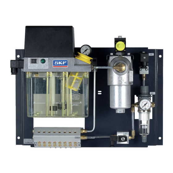
Page 14: Description Of Components
3. Design and function page 14 Details on the function and operation of the com- 3.5 Description of components Compressed air control valve (6) pact unit and the electronic control unit can be The compressed air control valve (6) is used to set Figure 1 shows an oil + air lubrication system;... - Page 15 3. Design and function page 15 Figure 1: Design of an electrically driven oil + air lubrication system Oil and air...
- Page 16 3. Design and function page 16 Pressure switch for minimum air pressure (8) Figure 2: MV20X-20 oil + air metering unit The pressure switch for minimum air pressure (8) is used to continuously monitor the air pressure set on the pressure control valve. As soon as the air pressure set on the pressure control valve falls below the minimum value set on the pressure switch, the pressure switch issues an electrical...
- Page 17 3. Design and function page 17 Oil + air metering unit (9) Figure 3: MV50X oil + air metering unit Oil + air metering units are available in two differ- ent model designs which differ in terms of available metered quantities of lubricant (see Table 5, Chap. 6.4).
- Page 18 3. Design and function page 18 The oil + air metering units of the MV50X series Oil + air metering units of series MV50X and Figure 4. Hydraulic diagram of an oil + air contain an externally mounted pressure-regulating MV20X-20 can be combined and utilized together lubrication system (schematic diagram, subject valve (Item 16, Fig.
- Page 19 3. Design and function page 19 Figure 4: Hydraulic diagram of oil + air lubrication system...
-
Page 20: Function
3. Design and function page 20 The oil + air lubrication system is ready for the next Note that the electric motor of the compact unit is 3.6 Function lubricating cycle. approved for operating mode S3 (intermittent A lubricating cycle of an oil + air lubrication system operation) and that minimum interval times and consisting of a compact unit and an oil + air me- To ensure proper metering, it is recommended... -
Page 21: Models And Designations
MV50X, max. 6 lubrication line connections Oil + air metering units can be combined and connected in series Design number: 01-99 - Two-digit sequence number (specified by SKF) Voltage key Specification of motor voltage and frequency +428 - 230 V, 50/60 Hz... -
Page 22: Installation Instructions
DIN VDE 0105 and IEC 364. documentation is available, you can di- rectly request the documentation from Before installing/positioning the oil + air lubrication SKF Lubrication Systems Germany system, remove the packaging material and any GmbH. transportation safety devices such as sealing plugs. -
Page 23: Mounting Dimensions
(e.g., DIN, VDE) must be strictly ob- SKF Lubrication Systems Germany it will not interfere with or be stuck served. Significant bodily injury and GmbH. -
Page 24: Inductive Loads
SKF Lubrication Systems Germany tation for the oil + air lubrication system. GmbH. If no documentation is available, you can... -
Page 25: Control And Monitoring
4. Installation instructions page 25 the period between two contact times. A lubricating The oil pressure switch responds once the required 4.4 Control and monitoring cycle consists of the contact time and the interval oil pressure has been reached. Oil + air lubrication systems are available in de- time. -
Page 26: Oil + Air Lubrication Systems With Control Unit
+ air lubrication system. The pump cycle time is 60 seconds and cannot be adjusted. If no documentation is available, you can request the documentation directly from SKF Lubrication Systems Germany GmbH. -
Page 27: Compressed Air Line Connection
4. Installation instructions page 27 Larger air volumes must be provided due to the The connection for the compressed air line is 4.5 Compressed air line connection greater adhesion of high-viscosity lubricants to the designed as an M10x1 pipe thread with a counter- The compressed air line must be connected to the wall of the lubrication point line. -
Page 28: Lubrication Line Connection
Lubrication point lines made of transparent plastic point line: SKF oil-streak sensors are recommended for are recommended so that the lubricant transport monitoring a continuous lubricant flow in the in the lubrication point lines (oil streak formation) Lubrication point line, plastic tubing Ø... - Page 29 4. Installation instructions page 29 1 …10 m Figure 5: Assembly structure for lubrication point line Oil + air metering unit 30 Hose coil 32 Nozzle...
-
Page 30: General Information About Laying Of
4. Installation instructions page 30 All components of the lubrication line system - 4.7 General information about laying of Danger! including pipes, hoses, cut-off valves, control Centralized lubrication systems must be lubrication line valves, fittings, and so on - must be carefully leak-tight. -
Page 31: Venting Oil+Air Mixing Valves Mv20X-20
Note that only the Service from the mixing valve (1). the metering units (5). department of SKF Lubrication Systems Germany • Remove the mixing valve (1) from the mounting • Repeat the process on all metering units. GmbH may change the metering units for 10 mm³... -
Page 32: Transport, Delivery And Storage
5. Transport, delivery and storage page 32 • Reconnect the compressed air supply. Bottom of mixing valve View rotated 180°... -
Page 33: Transport
33 5.3 Storage 5.3.3 Storage - general information 5. Transport, delivery and The following conditions apply to the storage of SKF Ensure that no dust gets into stored products storage Lubrication Systems Germany GmbH products. by wrapping them in plastic film Store products on racks or pallets to protect 5.1 Transport... -
Page 34: Operation
6. Operation page 34 Caution! 6.2 Commissioning 6. Operation Different lubricants cannot be mixed, as All electrical, hydraulic and pneumatic connections mixing may result in damage and ne- 6.1 General information must be inspected before commissioning the oil + cessitate costly and complicated cleaning air lubrication system. -
Page 35: Setting-Up Mode
Suitable nozzles tion point line, taking into account pressure losses 6 - 10 bar). can be ordered from SKF Lubrication Systems in the lubrication point line and the bearing assem- Run the compact unit until a continuous oil Germany GmbH. - Page 36 6. Operation page 36 With double-row cylindrical roller bearings, the The lubricant fed to the rolling bearing and the lubricant should be introduced into the rolling entire bearing assembly must be drained to prevent bearing from the side at the level of the outer ring an oil sump from forming in the lower part of the raceway.
- Page 37 6. Operation page 37 Figure 7: Lubricant delivery on various types of ball bearings Oil + air Exhaust...
-
Page 38: Setting The Lubricant Flow Rate
6. Operation page 38 6.4 Setting the lubricant flow rate There is no generally applicable formula for deter- Table 5: Available metering volumes for oil + air mining the quantity of lubricant per time unit that a metering units Caution! bearing requires. - Page 39 6. Operation page 39 The number of pulses per second is calculated Example for a typical configuration: using the following formulas: Interva l = 150 mm d = 30 mm with ...
- Page 40 6. Operation page 40 The standard design of the electronic control unit The interval time is programmed on the electronic Configuration of the interval time on the electronic for oil + air lubrication systems allows the interval control unit in minutes, so the minimum interval control unit is described in its operating instruc- time to be programmed.
-
Page 41: Setting The Air Flow Rate
6. Operation page 41 6.5 Setting the air flow rate This value applies to all oils of viscosity classes ISO Note: VG 32 to ISO VG 100. Higher values apply to The lubrication point outlet on the oil + air metering The amount of air required is based on the quanti- higher-viscosity oils and oils with bonding additives. -
Page 42: General Notes
6. Operation page 42 6.6 General notes Figure 4 shows the types of monitoring available in an oil + air lubrication system. Oil + air lubrication systems should always be started before applying full load to the ma- The following monitoring units are presented: chine/system's bearings, and must remain running after production until the bearings have cooled. -
Page 43: Shutdown
SKF Lubrication Systems Germany GmbH will take to the information in the sections 'Installation' and 'Startup’ of this owner’s manual. back the product and arrange for its legal disposal. Costs to the customer will be limited to SKF's incurred costs. -
Page 44: Maintenance
If you accidentally fill the product with an incorrect or contaminated lubricant, the inside of the product does have to be cleaned. If this occurs, contact SKF Danger! Lubrication Systems Germany GmbH Services for The described product may be under pressure when it is being operated. -
Page 45: Faults
All other work relating to installation, Dismantle motor, crank by hand: maintenance, and repair must only be If resistance is high, replace the motor. carried out by SKF Lubrication Systems Motor runs with difficulty Sluggish pump Measure motor current. If current is impermissibly Germany GmbH Service. - Page 46 Only tective gloves or when motor is no use original SKF spare parts. longer hot. If contaminated, clean the pressure-regulating valve. No pressure build-up in the Air in the main lubricant line.
-
Page 47: Technical Data
10. Technical data page 47 10. Technical data Designation Unit Values Oil + air lubrication system W x H x D dimensions with mounting plate Varies by design (see documentation) Weight (filled) Varies by design (see documentation) Number of connections 1 to 24 (>... -
Page 48: Technical Data (Cont.)
10. Technical data (cont.) page 48 10. Technical data (cont.) Designation Unit Values Oil + air outlet lubrication line M8x1, counterbore for double tapered sleeve pipe union for pipe Oil inlet connection M10x1, counterbore for double tapered sleeve pipe union for pipe Compressed air inlet connection M10x1, counterbore for double tapered sleeve pipe union for pipe Operating pressure... - Page 49 blank page...
- Page 50 blank page...
- Page 51 blank page...
- Page 52 Important product usage Information All SKF Lubrication Systems Germany GmbH products may only be used as intended and as described in the installation instructions. If the installation instructions are delivered with your product, read them carefully and follow them.
Need help?
Do you have a question about the OLA Series and is the answer not in the manual?
Questions and answers