SKF LINCOLN P203 Assembly Instructions Manual
Lubrication pump for multi-line lubrication systems dc versions with control pcb h
Hide thumbs
Also See for LINCOLN P203:
- Original assembly instructions (88 pages) ,
- Assembly instructions manual (84 pages) ,
- Assembly instructions manual (58 pages)

Related Manuals for SKF LINCOLN P203


Summary of Contents for SKF LINCOLN P203
- Page 1 Assembly instructions Lubrication pump P203 following machinery directive 2006/42/EC for multi-line lubrication systems DC versions with control PCB H LINCOLN LINCOLN LINCOLN LINCOLN LINCOLN 951-171-028-EN Version 01 28/03/2018...
-
Page 2: Ec Declaration Of Incorporation Acc. To Machinery Directive 2006/42/Ec
EC Declaration of incorporation EC Declaration of incorporation acc. to machinery directive 2006/42/EC The manufacturer, SKF Lubrication Systems Germany GmbH, Walldorf Facilities, Heinrich-Hertz-Str. 2-8, DE - 69190 Walldorf, hereby declares that the partly completed machinery Designation: Electrically driven pump to supply lubricant during intermittent operation within a centralized lubrication system... -
Page 3: Legal Disclosure
○ Intent or negligence Warranty Berlin Facilities The instructions do not contain any informa- ○ Use of non-original SKF spare parts Motzener Straße 35/37 tion on the warranty. This can be found in ○ Faulty planning or layout of the central- 12277 Berlin our general terms and conditions. -
Page 4: Table Of Contents
Table of contents Table of contents EC Declaration of incorporation acc. to machinery directive 2006/42/EC ..2 Legal disclosure ...................... 3 Explanation of symbols, signs and abbreviations ..........7 Safety instructions .................9 1.21 Cleaning ....................15 General safety instructions ..............9 1.22 Residual risks ..................16 General behaviour when handling the product ........ - Page 5 Table of contents Delivery, returns, and storage ............ 38 Initial start-up ................53 Delivery ....................38 Inspections prior to initial start-up .............53 Returns ....................38 Inspections during initial start-up ............53 Storage ....................38 Triggering an additional lubrication cycle...........54 Storage temperature range ..............38 Operation ..................55 Storage conditions for parts primed with lubricant ......39 Refill lubricant ..................55 5.5.1...
- Page 6 Table of contents Spare parts ................. 66 Electrical connection ..............72 14.1 Housing cover assy................66 15.1 Cable colours following IEC 60757 .............72 14.2 Pump elements ..................66 15.2 Connection diagram P203 V DC with control PCB H and 14.3 Pressure control valve and adapter ............67 square plug ....................73 14.4 Adapter D 6 AX 1/8NPT I C ..............67...
-
Page 7: Explanation Of Symbols, Signs And Abbreviations
Explanation of symbols, signs and abbreviations Explanation of symbols, signs and abbreviations The following abbreviations may be used within these instructions. Symbols within safety notes mark the kind and source of the hazard. General warning Dangerous electrical voltage Risk of falling Hot surfaces Unintentional intake Crushing hazard... - Page 8 Explanation of symbols, signs and abbreviations Abbreviations and conversion factors regarding °C degrees Celsius °F degrees Fahrenheit approx. approximately Kelvin ounce i.e. that is Newton fl. oz. fluid ounce poss. possibly hour inch if appl. if applicable second pounds per square inch incl.
-
Page 9: Safety Instructions
1. Safety instructions 1. Safety instructions 1.1 General safety instructions 1.2 General behaviour when handling the product ○ The owner must ensure that safety infor- ○ Responsibilities for different activities ○ The product may be used only in aware- mation has been read by any persons en- must be clearly defined and observed. -
Page 10: Intended Use
1. Safety instructions 1.3 Intended use 1.6 Prohibition of certain activities ○ to supply, transport, or store hazardous Supply of lubricants within a centralized lu- Due to potential sources of faults that may substances and mixtures in accordance brication system following the specifications, not be visible or due to legal regulations with annex I part 2-5 of the CLP regula- technical data and limits stated in these... -
Page 11: Notes Related To The Ce Marking
1. Safety instructions 1.11 ADR test certiicate 1.8 Notes related to the CE marking 1.9 Inspections prior to delivery CE marking is effected following the require- The following inspections were carried out Provided the use of ADR connecting mate- ments of the applied directives: prior to delivery: rial as stated in the type identification code ○... -
Page 12: Markings On The Product
1. Safety instructions 1.13 Notes related to the type identiica- 1.12 Markings on the product SKF Lubrication Systems Germany GmbH tion plate Model: P203-xxxxx-xxx-xx P. No.: 644-xxxxx-x The type identification plate states important S. No.: xxxxxxxxxxxx Warning of unintended intake by... -
Page 13: Persons Authorized To Operate The Pump
1. Safety instructions 1.15 Brieing of external technicians 1.14 Persons authorized to operate the 1.17 Operation pump The following must be observed during Prior to commencing the activities, external commissioning and operation: technicians must be informed by the opera- 1.14.1 Operator ○... -
Page 14: Transport, Installation, Maintenance, Malfunctions, Repair, Shutdown, Disposal
1. Safety instructions 1.19 Transport, installation, maintenance, ○ Ensure through suitable measures that ○ Carry out electrical connections only ac- malfunctions, repair, shutdown, movable or detached parts are immobi- cording to the information in the valid disposal lized during the work and that no limbs wiring diagram and taking the relevant ○... -
Page 15: Initial Commissioning / Daily Start-Up
1. Safety instructions 1.20 Initial commissioning / daily start-up 1.21 Cleaning ○ Risk of fire and explosion when using ○ All components used must be designed Ensure that: inflammable cleaning agents Only use ○ All safety devices are completely available according to the maximum operating non-flammable cleaning agents suitable pressure and the maximum respectively... -
Page 16: Residual Risks
1. Safety instructions 1.22 Residual risks Residual risk Possible in life cycle Prevention/ remedy Personal injury/ material damage due to Keep unauthorized persons away No people may remain under suspended loads. Lift A B C G H K falling of raised parts parts with adequate lifting devices. -
Page 17: Lubricants
2.3 Material compatibility 2.2 Selection of lubricants Lubricants are used specifically for cer- SKF considers lubricants to be an element Lubricants must generally be compatible tain application purposes. In order to fulfil of system design. A suitable lubricant is se-... -
Page 18: Ageing Of Lubricants
(e.g. "bleeding"). ard designations, if any, on the packaging have to be observed. Please contact SKF. if you have further ques- tions regarding lubricants. You may request an overview of the lubri- cants tested by SKF. -
Page 19: Overview, Functional Description
3. Overview, functional description 3. Overview, functional description Overview, functional description Fig. 1 3.1 Pumps without follower plate 1 Reservoir The lubricant is stored in the reservoir. De- pending on the pump version there are differ- ent types of reservoirs and reservoir sizes. 1.1 Reservoir lid Serves as a protection against contamination of the lubricant. - Page 20 3. Overview, functional description Overview, functional description Fig. 2 2 Pump housing The pump housing accommodates the motor, the electrical connection, the filler fitting, the Types of connections pump elements and the control PCB. Square plug 3 pump elements The pump can be equipped with up to 3 pump elements (see note in the type identification code).
- Page 21 3. Overview, functional description Overview, functional description Fig. 3 9 Screw cap of control PCB The screw cap (9) allows to see the operating or error states (LED displays on the control PCB). Remove the screw cap (9) by turning it anti- clockwise to trigger an additional lubrication or to adjust the lubrication time on the control PCB.
- Page 22 3. Overview, functional description Overview, functional description of control PCB H Fig. 4 11 Control PCB H Control PCB H serves to control P203 pumps on vehicle trailers without permanent power supply. The control PCB H is activated by the first braking of the vehicle after turning the vehicle’s ignition on.
- Page 23 3. Overview, functional description Overview, functional description of control PCB H Fig. 5 Functional principle: A capacitor on the control PCB H is charged by the power supply of the brake light each time the vehicle brake is actuated. In this way the power supply required for the control PCB to save the pause and lubrication times as well as to enable the function of the shock sensor...
- Page 24 3. Overview, functional description Overview, functional description of control PCB H Fig. 6 Setting options on the control PCB H After removing the screw cap (9) the following settings can be made. Setting of the lubrication time: To do so, turn the red rotary switch (11.1) into 11.2 11.1 the desired position.
-
Page 25: Technical Data
4. Technical data 4. Technical data 4.1 General technical data Operating pressure max. 350 bar [5076 psi] Input (voltage) 12 V DC pump 24 V DC pump Number of pump elements max. 3 Rated voltage 12 V DC ± 10 % 24 V DC ±... -
Page 26: Protection Types And Classes
4. Technical data 4.2 Protection types and classes 4.3 Hydraulic connection diagram 1 = Reservoir Degree of protection IP6K9K 2 = Pump Protection class 3 = Check valve - Square plug SELV / PELV / FELV - Bayonet plug SELV / PELV 4 = Pressure control valve R = Return line P = Pressure line... -
Page 27: Nominal Output Volumes
4. Technical data 4.4 Nominal output volumes The stated nominal outputs per stroke and pump element refer to NLGI 2 lubrication greases at an ambient temperature of + 20 °C [68 °F] and a back pressure of 100 bar [1450 psi] on the pump element. Deviating operating conditions or deviating pump configuration result in a changed motor speed and thus in a change of the output per time unit. -
Page 28: Output Diagrams Of Typical Nlgi 2 Lubricants
4. Technical data 4.4.2 Output diagrams of typical NLGI 2 lubricants Low temperature lubrication grease High temperature lubrication grease °C °C 86 104 122 °F 86 104 122 °F The output diagrams represent the average value of the different high- respectively low-temperature lubrication greases. Calculation of the output using the example of a high-temperature lubrication grease Nominal speed of the pump motor per minute x nominal output of pump element 7 per stroke x efficiency in percent at an assumed ambient temperature of -10 °C [14 °F] = 20 rpm x 0.22 cc (0.0134) x 80 % = 3.5 cc/min [0.214 cu.in./min.]. -
Page 29: Overview Of The Reservoir Variants
4. Technical data 4.5 Overview of the reservoir variants In the following you find the possible reservoir variants of the pumps described in these instructions (also see type identification code). For a better representation only the smallest possible reservoir size will be depicted always. In the figures the different reservoir variants may not ü... -
Page 30: Useable Reservoir Volume
4. Technical data 4.6 Useable reservoir volume Regarding the reservoir version without follower plate the useable reservoir volume mainly depends on the NLGI consistency class of the lubricant to be used and of the ambient temperature. In case of high consistency and low operating temperature normally more lubricant sticks to the inner surfaces of the reservoir and the pump and is thus no more available for being dispensed. -
Page 31: Lubricant Requirement For Priming Of An Empty Pump
4. Technical data 4.7 Lubricant requirement for priming of an empty pump To prime an empty pump up to the MAX marking of the reservoir, the following lubricant quantities are required. Nominal volume | Litres / [gal.] 2 [0.53] 4 [1.06] 8 [2.11] 11 [2.90] 15 [3.96]... -
Page 32: Tightening Torques
4. Technical data 4.8 Tightening torques A Pump element 20 Nm ± 2,0 Nm [14.75 ft.lb. ± 1.4 ft.lb.] B Pressure control valve 6 Nm -0,5 Nm [4.43 ft.lb. - 0.07 ft.lb.] C Pump 18 Nm ± 1.0 Nm [13.27 ft.lb. ± 0.74 ft.lb.] D Screw cap 2 Nm ±... -
Page 33: Possible Settings Of The Lubrication Times
4. Technical data 4.9 Possible settings of the lubrication times Position of the rotary switch (red) Lubrication time in minutes) Factory setting of the rotary switch (red) Reference to the "0" position of the rotary switches Never turn the rotary switches to the "0" position. This position is intended exclusively for the owner's purposes. 951-171-028 Version 01 - 33 -... -
Page 34: Type Identification Code
4. Technical data 4.10 Type identiication code The type identification code facilitates selection/ identification of important features of the product. For the type identification code of the respective prod- uct, see the type identification plate on the pump. P 2 0 3 _ E - _ 2 X N B O - 6 0 0 - 2 4 - E C 0 0 0 0 0 0 - H _ _ A + A D R Example H K H K H K H K Category 1 2 3... - Page 35 4. Technical data P 2 0 3 _ E - _ 2 X N B O - 6 0 0 - 2 4 - E C 0 0 0 0 0 0 - H _ _ A + A D R Example H K H K H K H K Category 1 2 3...
- Page 36 4. Technical data P 2 0 3 _ E - _ 2 X N B O - 6 0 0 - 2 4 - E C 0 0 0 0 0 0 - H _ _ A + A D R Example H K H K H K H K Category 1 2 3...
- Page 37 4. Technical data P 2 0 3 _ E - _ 2 X N B O - 6 0 0 - 2 4 - E C 0 0 0 0 0 0 - H _ _ A + A D R Example H K H K H K H K Category 1 2 3...
-
Page 38: Delivery, Returns, And Storage
5.3 Storage 5.4 Storage temperature range ○ In case of parts not filled with lubricant After receipt of the shipment, check the SKF products are subject to the following shipment for damage and completeness storage conditions: the admissible storage temperature cor- according to the shipping documents. -
Page 39: Storage Conditions For Parts Primed With Lubricant
5. Delivery, returns, and storage 5.5 Storage conditions for parts primed 5.5.3 Storage period exceeding 18 Metering devices with lubricant months • Remove all connection lines and closure To avoid dysfunctions consult the manufac- The conditions mentioned in the follow- screws, if any turer before commissioning. -
Page 40: Installation
6. Installation 6. Installation 6.2 Place of installation 6.1 General information ○ Possibly existing visual monitoring de- Protect the product against humidity, dust Only qualified technical personnel may install vices, e.g. pressure gauges, MIN/MAX and vibrations and install it in an easily ac- the products described in these Instructions. -
Page 41: Mechanical Connection
6. Installation 6.3 Mechanical connection 6.3.1 Minimum assembly dimensions Ensure sufficient space for maintenance work or for attachment of further components to build a centralized lubrication system to the pump by leaving a free space of at least 100 mm [3.94 in.] into each direction in addition to the stated dimensions. Reservoir Reservoir size Reservoir size... - Page 42 6. Installation Minimum assembly dimensions Fig. 7 LINCOLN LINCOLN LINCOLN LINCOLN LINCOLN 951-171-028 - 42 - Version 01...
-
Page 43: Installation Bores
6. Installation 6.3.2 Installation bores Pumps with 8 l [2.11 gal.] reservoir Pumps with 2 l [0.53gal.] or 4 l [1.06 gal.] reservoir Are fixed at the three lower fastening points NOTICE Are fixed at the two lower fastening points (A) or (B) and (C) of the pump housing. - Page 44 6. Installation Pumps with 11 l [2.9 gal.] or 15 l [3.96 gal.] Mounting bores for pumps with 11 l [2.9 gal.] or 15 l [3.96 gal.] reservoir Fig. 9 reservoir Are fixed on the lower mounting bores (A) or (B) of the pump housing and additionally on the 2 upper mounting points (D).
-
Page 45: Electrical Connection
6. Installation Electrical connection, Fig. 10 6.4 Electrical connection Types of connections WARNING Square plug Electric shock Make sure to disconnect the product from the power supply before carrying out any works on electrical components. Square plug Bayonet plug Carry out the electrical connection accor- Bayonet plug 4/3 ding to the connection type of the pump, •... -
Page 46: Adjusting The Output Volume On The Pump Element R
6. Installation Adjusting the output volume on pump element R Fig. 11 6.5 Adjusting the output volume on the pump element R The output of pump element R can be adjusted only while [0.0061] 0,18 the pump is idle. Factory [0.0054] 0,16 setting is full supply, i.e. -
Page 47: Mount Pressure Control Valve
6. Installation Mounting the pressure control valve Fig. 12 6.6 Mount pressure control valve Protect each pump element by means of a pressure control valve suitable for the planned maximum admissible operating pressure of the centralized lubrication system. Observe the information re- garding the adapter required for certain reservoir sizes given in chapter Overview of reser-... -
Page 48: Lubrication Line Connection
6. Installation 6.7 Lubrication line connection ○ The lubricant flow should not be impeded Observe the following installation instruc- CAUTION tions for safe and smooth operation. by the installation of sharp elbows, angle valves, gaskets protruding to the inside, ○ Use clean components and primed lubri- Risk of falling or cross-section changes (big to small). -
Page 49: Filling With Lubricant
6. Installation Filling via the reservoir lid Fig. 13 6.8 Filling with lubricant 6.8.1 Filling via the reservoir lid WARNING Crushing hazard on the rotating stirring paddle. Fill- ing via the reservoir lid is allowed only after disconnecting the pump from the power supply by removing it from the connection (5.1). -
Page 50: Filling Via Filler Fitting
6. Installation 6.8.2 Filling via iller itting Filling via filler fitting Fig. 14 • Connect filling connection of filler pump with filler fitting (4) • Switch on filler pump and fill reservoir until shortly below the MAX marking • Switch filler pump off and remove it from filler fitting (4) of pump 951-171-028 - 50 -... -
Page 51: Filling Via The Optional Filling Connection
6. Installation 6.8.3 Filling via the optional illing Filling with lubricant via filling connection Fig. 15 connection • Unscrew protective cap (20.1) from fill- ing connection (20) anticlockwise • Connect filling connection of filler pump with filler fitting (20) • Switch on filler pump and fill reservoir until shortly below the MAX marking •... -
Page 52: Setting Of The Lubrication Times
6. Installation Set the lubrication time Fig. 16 6.9 Setting of the lubrication times As a standard lubrication times are set/ changed via the red rotary switch on the control PCB. • Remove screw cap (9) including seal- 11.1 ing ring •... -
Page 53: Initial Start-Up
7. Initial start-up 7. Initial start-up In order to warrant safety and function, a person assigned by the operator must carry out the following inspections. Immediately eliminate detected deficiencies. Deficiencies may be remedied by an authorized and qualified specialist only. Start-up check list 7.1 Inspections prior to initial start-up Electrical connection carried out correctly. -
Page 54: Triggering An Additional Lubrication Cycle
7. Initial start-up Trigger an additional lubrication Fig. 17 7.3 Triggering an additional lubrication cycle To trigger an additional lubrication cycle proceed as follows: 11.3 • Remove screw cap (9) including seal- ing ring • Press the pushbutton (11.3) to trigger an additional lubrication cycle on the control PCB (>... -
Page 55: Operation
8. Operation 8. Operation SKF products operate automatically to the greatest possible extent. Basically, activities during standard opera- tion are limited to the control of the filling level of pumps without low-level indication and the timely refilling of lubricant. 8.1 Reill lubricant... -
Page 56: Cleaning
• Thorough cleaning of all outer surfaces uct will be required. Thoroughly remove residues of with a damp cloth To do so, contact the SKF Customer Service. cleaning agents from the product Make sure to keep the reser- and rinse off with clear water. -
Page 57: Maintenance
10. Maintenance Maintenance Regular and appropriate maintenance is a prerequisite to detect and clear faults in time. The specific timelines have to be determined, verified at regular intervals and adapted, if necessary, by the operator based on the operating conditions. If needed, copy the table for regular mainte- nance activities. -
Page 58: Troubleshooting
11. Troubleshooting Troubleshooting Fault table 1 Fault Possible cause Remedy Check whether one of the indicated faults is present and remedy it in the frame of responsibilities. ○ Power supply to pump interrupted Faults outside of your own responsibility have to be re- ○... - Page 59 11. Troubleshooting Fault table 2 Fault Possible cause Remedy ○ Blockade, fault within the centralized lubrication system ○ Defective check valve ○ Defective pressure relief valve Check whether one of the indicated faults is present and rem- ○ Suction bore of pump element is clogged edy it in the frame of responsibilities.
-
Page 60: Display Of Operating States Of Control Pcb H
11. Troubleshooting 11.1 Display of operating states of control PCB H Status Meaning left No (sufficient) operating voltage, control pcb defective, both LEDs off right left Operating voltage is present, left LED is lit permanently, right LED is off. Normal operating state during pause time right left... -
Page 61: Repairs
12. Repairs Repairs 12.1 Check pump element and replace Replace pump element Fig. 18 WARNING pressure control valve. Risk of injury The characteristics of the new Before carrying out any repair work, pump element must correspond take at least the following safety to the characteristics of the pump measures: element to be replaced. -
Page 62: Replacement Of The Control Pcb
12. Repairs Unscrew housing cover Fig. 19 Control PCB removed Fig. 21 12.2 Replacement of the control PCB The work should possibly be done at room temperature At low temperatures the re- placement may be subject to restrictions. To facilitate replacement of the control PCB the pump should be tilted into hori- zontal position. -
Page 63: Installation Of The Pump At The Place Of Use
12. Repairs Mount drain hose Fig. 22 Mount housing cover Fig. 24 • Note down any changed jumper posi- tions and rotary switch positions and apply them to the new control PCB 12.1 • Place control PCB into lateral guide rails and carefully press it down •... -
Page 64: Tests After Replacement Of The Control Pcb
12. Repairs 12.4 Tests after replacement of the con- trol PCB After replacement of a control pcb carry out an electrical safety test according to ISO 60204-1. Filing After the replacement of the control PCB the scope and findings of the test have to be recorded in writing and handed over for filing to the person responsible for machine operation. -
Page 65: Shutdown And Disposal
13. Shutdown and disposal Shutdown and disposal 13.1 Temporary shutdown 13.3 Disposal Countries outside the European Union Temporarily shut the system down by: Countries within the European Union The disposal has to be done according to the ○ Switching off the superior machine Disposal should be avoided or minimized valid national regulations and laws of the wherever possible. -
Page 66: Spare Parts
14. Spare parts Spare parts The spare parts assemblies may be used exclusively for replacement of identical defective parts. Modifications with spare parts on existing products are not allowed. Exceptions to this are the pump elements and the optional filling connection. 14.1 Housing cover assy. -
Page 67: Pressure Control Valve And Adapter
14. Spare parts 14.3 Pressure control valve and adapter Fig. 27 Designation Qty. Part number Pressure control valve SVTS-350-R 1/4-D6 | C3 624-28894-1 Pressure control valve SVTS-350-R 1/4-D6 | C5-M 624-29343-1 Pressure control valve SVET-350-G 1/4 A-D8 | C3 624-29054-1 Pressure control valve SVTSV-270-R1/4-1/8NPTFI-NIP00R-A | C3 270864 Adapter S2520 1/4 -1/4 with PTFE sealing... -
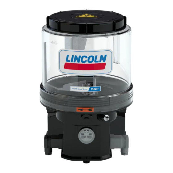
Page 68: Transparent Reservoir
8 l XNBO 1,2,3 544-31999-1 -MAX- -MAX- LINCOLN LINCOLN -MIN- -MIN- Delivery incl. 1= Lincoln/SKF Logo; 2= Directional arrow; 3= O-ring; 4 = Reservoir lid (not detachable) 544-31998-1 544-31999-1 -MAX- -MAX- Other transparent reservoirs on request LINCOLN LINCOLN -MIN- -MIN-... -
Page 69: Replacement Kit Control Pcb H
14. Spare parts 14.7 Replacement kit control PCB H Fig. 31 Designation Qty. Part number Replacement kit control PCB H 544-60242-1 Delivering including housing cover, drain hose, and the corresponding number of screws required for installation 14.8 Adapter with lubrication itting Fig. -
Page 70: Screw Cap
14. Spare parts Fig. 34 14.10 Screw cap Designation Qty. Part number Screw cap at pump housing 444-74158-1 14.11 Fixed paddle Fig. 35 Designation Qty. Part number Fixed paddle 4 XNBO 444-70490-1 Fixed paddle 8 XNBO (without figure) 444-70491-1 14.12 Reservoir lid Fig. -
Page 71: Connection Sockets And Cable
14. Spare parts 14.13 Connection sockets and cable Feature* Designation Qty. Part number Fig. 37 Connection socket with gasket and screw 544-32850-1 Connection cable 10 m [33 ft] with connection socket 664-36078-7 Connection cable 10 m [33 ft] ADR with connection socket 664-36862-1 Connection cable 10 m [33 ft] with bayonet socket (4/3 poles)H) 664-34167-6... -
Page 72: Electrical Connection
15. Connection diagrams Electrical connection 15.1 Cable colours following IEC 60757 Abbreviation Colour Abbreviation Colour Abbreviation Colour Abbreviation Colour black green white pink brown yellow orange turquoise blue violet ----- ----- The assignment of the following electrical connection diagrams is done according to the respective referenced type identification code characteris- tics. -
Page 73: Connection Diagram P203 V Dc With Control Pcb H And Square Plug
15. Connection diagrams 15.2 Connection diagram P203 V DC with control PCB H and square plug Connection diagram P203 V AC with control PCB H and square plug Fig. 38 31 30 15 3 2 1 0 No connection Motor E Square plug - control pcb / supply line 0 Without connecting socket, without cable 1 With connecting socket, without cable... -
Page 74: Connection Diagram P203 V Dc With Control Pbc H And Bayonet Plug
15. Connection diagrams 15.3 Connection diagram P203 V DC with control PBC H and bayonet plug Connection diagram P203 V AC with control PCB H and bayonet plug 4/3 Fig. 39 31 30 15 3 2 1 Motor 0 No connection 5 Bayonet plug, 4/3-pole n.c. - Page 75 Notes...
- Page 76 Notes...
- Page 77 Notes...
- Page 78 SKF Lubrication Systems Germany GmbH Walldorf Facilities Heinrich-Hertz-Str. 2-8 DE - 69190 Walldorf Phone: +49 (0) 6227 33-0 Fax: +49 (0) 6227 33-259 e-mail: Lubrication-germany@skf.com www.skf.com/lubrication 951-171-028-EN Version 01 28/03/2018...
Need help?
Do you have a question about the LINCOLN P203 and is the answer not in the manual?
Questions and answers