Table of Contents
Advertisement
Quick Links
Installation and Operation Manual
X-VA-MT3809G-MT3810G-eng
Part Number: 541B182AAG
December, 2014
®
Brooks
Models MT3809G and MT3810G
Metal Tube Variable Area Flowmeters
Explosion Proof Housing
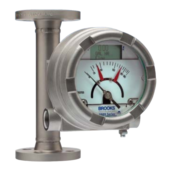
Model MT3809G
General Purpose Housing
Model MT3809G
Models MT3809G & MT3810G
Model MT3809G
Intrinsically Safe Housing
Advertisement
Table of Contents

Subscribe to Our Youtube Channel
Related Manuals for Brooks Instrument MT3809G


Summary of Contents for Brooks Instrument MT3809G
- Page 1 Installation and Operation Manual X-VA-MT3809G-MT3810G-eng Part Number: 541B182AAG Models MT3809G & MT3810G December, 2014 ® Brooks Models MT3809G and MT3810G Metal Tube Variable Area Flowmeters Model MT3809G General Purpose Housing Model MT3809G Model MT3809G Explosion Proof Housing Intrinsically Safe Housing...
- Page 2 Installation and Operation Manual X-VA-MT3809G-MT3810G-eng Part Number: 541B182AAG Models MT3809G & MT3810G December, 2014...
- Page 3 We appreciate this opportunity to service your flow measurement and control requirements with a Brooks Instrument device. Every day, flow customers all over the world turn to Brooks Instrument for solutions to their gas and liquid low-flow applications. Brooks provides an array of flow measurement and control products for various industries from biopharmaceuticals, oil and gas, fuel cell research and chemicals, to medical devices, analytical instrumentation, semiconductor manufacturing, and more.
- Page 4 Installation and Operation Manual X-VA-MT3809G-MT3810G-eng Part Number: 541B182AAG Models MT3809G & MT3810G December, 2014 THIS PAGE WAS INTENTIONALLY LEFT BLANK...
-
Page 5: Table Of Contents
Installation and Operation Manual Contents X-VA-MT3809G-MT3810G-eng Part Number: 541B182AAG Models MT3809G & MT3810G December, 2014 Paragraph Page Number Number Section 1 Introduction Description ............................ 1-1 Design Features ..........................1-1 Meter Specifications ........................1-1 Optional Accessories ........................1-9 Optional Electronic Equipment ...................... 1-9 1-5-1 Transmitter with or without Alarms Display and Pulse Output ............ - Page 6 Exploded View, Model MT3809G and MT3810G - Gas Service ........... 4-5 Exploded View, Model MT3809G and MT3810G - Liquid Service ..........4-6 Exploded View, Model MT3809G, Size 15 (Gas or Liquid Service Only) ........4-7 Exploded View, Model MT3809G, Size 16 (Liquid Service Only) ..........4-7 Meter Float Replacement &...
-
Page 7: Description
Installation and Operation Manual Section 1 Introduction X-VA-MT3809G-MT3810G-eng Part Number: 541B182AAG Models MT3809G & MT3810G December, 2014 1-1 Descripton ® The Brooks Models MT3809 and MT3810 are rugged, all metal flowmeters offering reliable operation based on the variable area principle. - Page 8 Installation and Operation Manual Section 1 Introduction X-VA-MT3809G-MT3810G-eng Part Number: 541B182AAG Models MT3809G & MT3810G December, 2014 Table 1-1 Specifications Meter MT3809 MT3809 MT3809 MT3809 MT3809 MT3809 ELF MT3809 ELF MT3809 ELF MT3809 ELF MT3809 ELF TFE Lined TFE Lined...
- Page 9 Installation and Operation Manual Section 1 Introduction X-VA-MT3809G-MT3810G-eng Part Number: 541B182AAG Models MT3809G & MT3810G December, 2014 Table 1-2A Model MT3809/MT3810 Capacities, Pressure Drop and Viscosity Immunity Ceiling Table 1-2B Model MT3809 ETFE Lined Capacities, Pressure Drop and Viscosity Immunity Ceiling...
- Page 10 Installation and Operation Manual Section 1 Introduction X-VA-MT3809G-MT3810G-eng Part Number: 541B182AAG Models MT3809G & MT3810G December, 2014 Table 1-3A Model MT3809/MT3810 Pressure Ratings, Flanged Table 1-3B Model MT3809/MT3810 Pressure Ratings, NPT Female...
- Page 11 Installation and Operation Manual Section 1 Introduction X-VA-MT3809G-MT3810G-eng Part Number: 541B182AAG Models MT3809G & MT3810G December, 2014 Table 1-3C Model MT3809/MT3810 Pressure Ratings, NPT Male Table 1-4 Temperature Cut-off Tables...
- Page 12 Installation and Operation Manual Section 1 Introduction X-VA-MT3809G-MT3810G-eng Part Number: 541B182AAG Models MT3809G & MT3810G December, 2014 Model 3809 & 3810 General Purpose Indicator Housing with Threaded Female St'd Connections mm [inches] 141 5.57 98 3.85 A 1.5[1/16] 137 5.40 Model 3809 &...
- Page 13 Installation and Operation Manual Section 1 Introduction X-VA-MT3809G-MT3810G-eng Part Number: 541B182AAG Models MT3809G & MT3810G December, 2014 Model 3809 Intrinsically Safe Indicator Housing with Threaded Female St'd Connections mm [inches] 160 6.29 A 1.5[1/16] 160 6.29 Model 3809 Intrinsically Safe Indicator Housing with Flanged Connections mm [inches] 160 6.29...
- Page 14 Installation and Operation Manual Section 1 Introduction X-VA-MT3809G-MT3810G-eng Part Number: 541B182AAG Models MT3809G & MT3810G December, 2014 Model 3809 Explosion Proof Indicator Housing with Threaded Female St'd Connections mm [inches] A 1.5[1/16] 172 6.75 165 6.50 Model 3809 Explosion Proof Indicator Housing with Flanged Connections mm [inches] 172 6.75...
-
Page 15: Optional Accessories
Installation and Operation Manual Section 1 Introduction X-VA-MT3809G-MT3810G-eng Part Number: 541B182AAG Models MT3809G & MT3810G December, 2014 1-4 Optional Accessories Needle valves and flow controllers may be externally piped into the inlet or outlet side of the instrument. Needle valves can be supplied up to size 12 1-1/2"... - Page 16 Installation and Operation Manual Section 1 Introduction X-VA-MT3809G-MT3810G-eng Part Number: 541B182AAG Models MT3809G & MT3810G December, 2014 Table 1-5 Approval Certificates Declarations Model Type Applicable Standards/ Directives Certificate/Status EC Declaration EMC Directive (2004/108/EC) Approved RoHS Directive (2011/65/EU) Approved Pressure Equipment Directive (97/23/EC)
- Page 17 Installation and Operation Manual Section 1 Introduction X-VA-MT3809G-MT3810G-eng Part Number: 541B182AAG Models MT3809G & MT3810G December, 2014 Table 1-8 Hazardous Location Certification: Intrinsic Safety (ia) / Non-sparking (nA) Model Type : Intrinsic safety (ia) / non-sparking (nA) Ambient -40°C to 70°C, Aluminum Housing –...
- Page 18 Installation and Operation Manual Section 1 Introduction X-VA-MT3809G-MT3810G-eng Part Number: 541B182AAG Models MT3809G & MT3810G December, 2014 Table 1-8 Hazardous Location Certification: Intrinsic Safety (ia) / Non-sparking (nA) (Continued) Electrical data Apparatus equipped with loop 4-20 mA circuit (J1 terminals 12+ and 13-):...
- Page 19 Installation and Operation Manual Section 1 Introduction X-VA-MT3809G-MT3810G-eng Part Number: 541B182AAG Models MT3809G & MT3810G December, 2014 Table 1-9 Process and Ambient Temperature Limits: Intrinsic Safety (ia) / Non-sparking (nA) Maximum Process Temperature (°C) Meter Option Without Digital Display With or without Digital Display...
- Page 20 Installation and Operation Manual Section 1 Introduction X-VA-MT3809G-MT3810G-eng Part Number: 541B182AAG Models MT3809G & MT3810G December, 2014 T T T T T r r r r r ansmitter Description ansmitter Description ansmitter Description ansmitter Description T T T T T able...
- Page 21 Installation and Operation Manual Section 1 Introduction X-VA-MT3809G-MT3810G-eng Part Number: 541B182AAG Models MT3809G & MT3810G December, 2014 Alarm wiring diagrams Refer to Figures 1-7 and 1-8. Alarm accessories Amplifier power supply (approved isolated barrier) 1 or 2 channel approved for intrinsically safe application, remotely mounted, 115 or 230 Vac power.
- Page 22 Installation and Operation Manual Section 1 Introduction X-VA-MT3809G-MT3810G-eng Part Number: 541B182AAG Models MT3809G & MT3810G December, 2014 1-5-3 Microprocessor Transmitter with or without Inductive Alarms This combined system provides both the sophistication of the microprocessor along with the simplicity of one or two switch inductive alarms.
- Page 23 Installation and Operation Manual Section 1 Introduction X-VA-MT3809G-MT3810G-eng Part Number: 541B182AAG Models MT3809G & MT3810G December, 2014 Figure 1-4A Wiring Diagram, Model MT3809 Transmitter, 4-20 mA 1-17...
- Page 24 Installation and Operation Manual Section 1 Introduction X-VA-MT3809G-MT3810G-eng Part Number: 541B182AAG Models MT3809G & MT3810G December, 2014 Figure 1-4B Wiring Diagram, Model MT3809 Transmitter, 4-20 mA 1-18...
- Page 25 Installation and Operation Manual Section 1 Introduction X-VA-MT3809G-MT3810G-eng Part Number: 541B182AAG Models MT3809G & MT3810G December, 2014 Figure 1-5A Wiring Diagram, Model MT3809, 4-20 mA Transmitter, One or Two Optical Alarms and PPU 1-19...
- Page 26 Installation and Operation Manual Section 1 Introduction X-VA-MT3809G-MT3810G-eng Part Number: 541B182AAG Models MT3809G & MT3810G December, 2014 Figure 1-5B Wiring Diagram, Model MT3809, 4-20 mA Transmitter, One or Two Optical Alarms and PPU 1-20...
- Page 27 Installation and Operation Manual Section 1 Introduction X-VA-MT3809G-MT3810G-eng Part Number: 541B182AAG Models MT3809G & MT3810G December, 2014 Figure 1-6A Wiring Diagram, Model MT3809 Explosion Proof, 4-20 mA Transmitter with Inductive Alarms, Optical Alarms and PPU 1-21...
- Page 28 Installation and Operation Manual Section 1 Introduction X-VA-MT3809G-MT3810G-eng Part Number: 541B182AAG Models MT3809G & MT3810G December, 2014 Figure 1-6B Wiring Diagram, Model MT3809 Explosion Proof, 4-20 mA Transmitter with Inductive Alarms, Optical Alarms and PPU 1-22...
- Page 29 Installation and Operation Manual Section 1 Introduction X-VA-MT3809G-MT3810G-eng Part Number: 541B182AAG Models MT3809G & MT3810G December, 2014 Figure 1-7A Wiring Diagram, Model MT3809, One or Two Inductive Alarms 1-23...
- Page 30 Installation and Operation Manual Section 1 Introduction X-VA-MT3809G-MT3810G-eng Part Number: 541B182AAG Models MT3809G & MT3810G December, 2014 Figure 1-7B Wiring Diagram, Model MT3809, One or Two Inductive Alarms 1-24...
- Page 31 Installation and Operation Manual Section 1 Introduction X-VA-MT3809G-MT3810G-eng Part Number: 541B182AAG Models MT3809G & MT3810G December, 2014 Figure 1-8A Wiring Diagram, Model MT3809, 4-20 mA Transmitter, One or Two Inductive Alarms 1-25...
- Page 32 Installation and Operation Manual Section 1 Introduction X-VA-MT3809G-MT3810G-eng Part Number: 541B182AAG Models MT3809G & MT3810G December, 2014 Figure 1-8B Wiring Diagram, Model MT3809, 4-20 mA Transmitter, One or Two Inductive Alarms 1-26...
- Page 33 Installation and Operation Manual Section 1 Introduction X-VA-MT3809G-MT3810G-eng Part Number: 541B182AAG Models MT3809G & MT3810G December, 2014 Loop Voltage vs. Load Resistance 1050 Loop Resistance (maximum ohms) = 30 X voltage + 16 1000 Loop Voltage Note: load resistance should also include I.S. barrier resistance. When using HART communicator the minimum load resistance is 250 ohms.
- Page 34 Installation and Operation Manual Section 1 Introduction X-VA-MT3809G-MT3810G-eng Part Number: 541B182AAG Models MT3809G & MT3810G December, 2014 THIS PAGE WAS INTENTIONALLY LEFT BLANK 1-28...
-
Page 35: General
2-3 Recommended Storage Practices If intermediate or long-term storage is required for equipment, as supplied by Brooks Instrument, it is recommended that the equipment be stored in accordance with the following: a. Within the original shipping container. b. Stored in a sheltered area, preferably a warm, dry, heated warehouse. -
Page 36: Return Shipment
Instrument must have been purged in accordance with the following: All flow instruments returned to Brooks requires completion of Form RPR003-1, Brooks Instrument Decontamination Statement, along with a Material Safety Data Sheet (MSDS) for the fluid(s) used in the instrument. Failure to provide this information will delay processing by Brooks personnel. - Page 37 Installation and Operation Manual Section 2 Installation X-VA-MT3809G-MT3810G-eng Part Number: 541B182AAG Models MT3809G & MT3810G December, 2014 Recommended installation for Models MT3809 and MT3810 is as follows: a. Carefully remove the covers from each end of the flowmeter. The float may be fixed to avoid damage during transport.
-
Page 38: Installation And Maximum Torques Of Model Mt3809 Etfe
Section 2 Installation Installation and Operation Manual X-VA-MT3809G-MT3810G-eng Part Number: 541B182AAG Models MT3809G & MT3810G December, 2014 2-5-1 Installation and Maximum Torques of Model MT3809 ETFE MAXIMUM TORQUES MODEL MT3809 ETFE Please refer to Table 2-1 below. • Select bolts and gaskets (customer supply) in keeping with the flange pressure rating or the operating pressure. - Page 39 Section 2 Installation X-VA-MT3809G-MT3810G-eng Part Number: 541B182AAG Models MT3809G & MT3810G December, 2014 Range parameter is set at 500 and the AO Lo-Range is set at 100. Like other common parameters, the AO Hi-Range and AO Lo-Range can be set by Brooks prior to shipment.
- Page 40 Section 2 Installation Installation and Operation Manual X-VA-MT3809G-MT3810G-eng Part Number: 541B182AAG Models MT3809G & MT3810G December, 2014 6. After installation and powering of the loop, the transmitter must be zeroed, both electrically and mechanically. This operation will compensate for any stray magnetic effects in the vicinity of the transmitter. Flow must be verified to be zero when the zero function is momentarily activated.
-
Page 41: Installation Of The Model Mt3809 Flowmeter With A Transmitter With Inductive Alarms (1 Or 2 Switches)
Section 2 Installation X-VA-MT3809G-MT3810G-eng Part Number: 541B182AAG Models MT3809G & MT3810G December, 2014 4. The shielded cable must be used for hook up. The shield should be connected to chassis ground at the transmitter end and should be taped up and not connected at the receiver end. -
Page 42: Installation Of The Model Mt3809 Flowmeter With Transmitter And Digital Display And Inductive Alarms
Section 2 Installation Installation and Operation Manual X-VA-MT3809G-MT3810G-eng Part Number: 541B182AAG Models MT3809G & MT3810G December, 2014 2. Intrinsically safe installations require the use of relay isolators for the alarms and a barrier for the transmitter, if equipped. Power supply limits and cable parameters must be as shown in the installation diagram. -
Page 43: Pre-Start Check
Installation and Operation Manual Section 3 Operation X-VA-MT3809G-MT3810G-eng Part Number: 541B182AAG Models MT3809G & MT3810G December, 2014 3-1 Pre-Start Check After the flowmeter has been properly installed in the process, it is ready for operation. When initiating flow, slowly open the valve to avoid a flow surge. -
Page 44: Operation Of The Model Mt3809 Flowmeter With A Transmitter With Or Without Optional Alarms And Pulse Output For Totalization
Section 3 Operation Installation and Operation Manual X-VA-MT3809G-MT3810G-eng Part Number: 541B182AAG Models MT3809G & MT3810G December, 2014 3-3 Operation of the Model MT3809 Flowmeter with a Transmitter with or without Optional Alarms and Pulse Output for Totalization * Start-up the meter as described in Section 3-2. - Page 45 Installation and Operation Manual Section 3 Operation X-VA-MT3809G-MT3810G-eng Part Number: 541B182AAG Models MT3809G & MT3810G December, 2014 Figure 3-1 Model MT3809 Electronics Basic Setup Menu Tree...
- Page 46 Section 3 Operation Installation and Operation Manual X-VA-MT3809G-MT3810G-eng Part Number: 541B182AAG Models MT3809G & MT3810G December, 2014 Figure 3-2 Model MT3809 Electronics Detailed Setup Menu Tree...
- Page 47 Section 3 Operation X-VA-MT3809G-MT3810G-eng Part Number: 541B182AAG Models MT3809G & MT3810G December, 2014 The alarms may be set at the minimum and maximum flow rate or at any other preferred high and low limits. The units of measure of the alarm limits are the same units of measure as the process variable itself.
- Page 48 Section 3 Operation Installation and Operation Manual X-VA-MT3809G-MT3810G-eng Part Number: 541B182AAG Models MT3809G & MT3810G December, 2014 Figure 3-3 Model MT3809 Electronics LOI Chart Menu...
-
Page 49: Operation Of The Model Mt3809 Flowmeter With A Transmitter And Inductive Alarms (1 Or 2 Switches)
Installation and Operation Manual Section 3 Operation X-VA-MT3809G-MT3810G-eng Part Number: 541B182AAG Models MT3809G & MT3810G December, 2014 3-4 Operation of the Model MT3809 Flowmeter with a Transmitter and Inductive Alarms (1 or 2 switches) a. Start-up the meter as described in Section 3-2. - Page 50 Section 3 Operation Installation and Operation Manual X-VA-MT3809G-MT3810G-eng Part Number: 541B182AAG Models MT3809G & MT3810G December, 2014 THIS PAGE WAS INTENTIONALLY LEFT BLANK...
-
Page 51: General Service Information
Installation and Operation Manual Section 4 Maintenance X-VA-MT3809G-MT3810G-eng Part Number: 541B182AAG Models MT3809G & MT3810G December, 2014 4-1 General Service Information... -
Page 52: Meter Float Replacement And Cleaning (Mt3809 & Mt3810)
Section 4 Maintenance Installation and Operation Manual X-VA-MT3809G-MT3810G-eng Part Number: 541B182AAG Models MT3809G & MT3810G December, 2014 WARNING If this equipment is not properly serviced, serious personal injury and/or damage to the equipment can result from potentially high operating pressures. Process line pressure should be removed prior to servicing. - Page 53 Installation and Operation Manual Section 4 Maintenance X-VA-MT3809G-MT3810G-eng Part Number: 541B182AAG Models MT3809G & MT3810G December, 2014 c. Size 8 (½") flanged, gas service 1. Remove the meter from the process line and lay the meter horizontal on a table.
- Page 54 Section 4 Maintenance Installation and Operation Manual X-VA-MT3809G-MT3810G-eng Part Number: 541B182AAG Models MT3809G & MT3810G December, 2014 4. Reassemble by inserting the float assembly inside the conical taper (as well as the spacer bushing, size 16 only). Then insert the complete float assembly into the bottom of the meter.
- Page 55 Installation and Operation Manual Section 4 Maintenance X-VA-MT3809G-MT3810G-eng Part Number: 541B182AAG Models MT3809G & MT3810G December, 2014 Figure 4-1 Exploded View, Model MT3809G and MT3810G - Gas Service...
- Page 56 Section 4 Maintenance Installation and Operation Manual X-VA-MT3809G-MT3810G-eng Part Number: 541B182AAG Models MT3809G & MT3810G December, 2014 Figure 4-2 Exploded View, Model MT3809G and MT3810G - Liquid Service...
- Page 57 Installation and Operation Manual Section 4 Maintenance X-VA-MT3809G-MT3810G-eng Part Number: 541B182AAG Models MT3809G & MT3810G December, 2014 Figure 4-3 Exploded View, Model MT3809G, Size 15 (Gas or Liquid Service Only) Figure 4-4 Exploded View, Model MT3809G, Size 16 (Liquid Service Only)
-
Page 58: Meter Float Replacement And Cleaning (Mt3809 Etfe Option)
Section 4 Maintenance Installation and Operation Manual X-VA-MT3809G-MT3810G-eng Part Number: 541B182AAG Models MT3809G & MT3810G December, 2014 4-3 Meter Float Replacement and Cleaning (MT3809 ETFE Option) (Refer to Figure 4-5) Flanged connections, all sizes, liquid or gas a. Remove the meter from the process line and lay the meter horizontal on a table. - Page 59 Installation and Operation Manual Section 4 Maintenance X-VA-MT3809G-MT3810G-eng Part Number: 541B182AAG Models MT3809G & MT3810G December, 2014 Sizes 7 & 8 Sizes 10, 12 & 13 Figure 4-5 Meter Float Replacement & Cleaning (ETFE Option) k. Replace the scale and tighten two clamping screws. Make sure that the alarm switch wires do not interfere with the alarm cam.
-
Page 60: Transmitter Replacement With Inductive Alarms
Section 4 Maintenance Installation and Operation Manual X-VA-MT3809G-MT3810G-eng Part Number: 541B182AAG Models MT3809G & MT3810G December, 2014 4-7 Transmitter Replacement with Inductive Alarms The transmitter is a self contained unit matched specifically to the associated flowmeter. If there is a need to replace, please contact your nearest authorized Brooks service representative. -
Page 61: Essential Instructions
Section A Essential Instructions Installation and Operation Manual X-VA-MT3809G-MT3810G-eng Part Number: 541B182AAG December, 2014 Models MT3809G & MT3810G Bulgarian Brooks Instrument Brooks Instrument. Brooks Instrument : (1) . (2) Brooks Instrument (PED) 0,5 bar (g) 25 mm 1" ( (PED). - Page 62 P ed instalací si p e t te následující instrukce! Spole nost Brooks Instrument konstruuje, vyrábí a testuje tento produkt tak, aby splnil mnoho národních a mezinárodních standard . P ístroje musí být ádn nainstalovány, používány a udržovány tak, aby byl zajišt n jejich nep etržitý provoz v rámci normálních technických specifikací. Musíte dodržovat následující...
- Page 63 Installation and Operation Manual X-VA-MT3809G-MT3810G-eng Part Number: 541B182AAG December, 2014 Models MT3809G & MT3810G Dansk Grundlæggende vejledninger Læs disse før anvendelse! Brooks Instruments designer, fremstiller og afprøver sine produkter således, at de tilpasser sig både de indenrigs og internationale standarder. Disse udstyr bør installeres, bruges og repareres omhyggeligt, så...
- Page 64 Lees ze voordat u verder gaat! Brooks Instrument ontwerpt, produceert en test haar producten zodanig dat ze voldoen aan vele nationale en internationale normen. Deze producten moeten correct worden geïnstalleerd, bediend en onderhouden zodat ze binnen hun normale specificaties blijven werken. De volgende instructies moeten worden toegevoegd aan en geïntegreerd in uw veiligheidsprogramma als u producten van Brooks Instrument installeert, bedient en onderhoudt.
- Page 65 Olulised juhised Enne kasutamist lugege hoolikalt läbi! Brooks Instrument konstrueerib, valmistab ja katsetab oma tooteid selliselt, et need vastaksid paljude erinevate riiklike ja rahvusvaheliste standardite nõuetele. Ainult nõuetekohane paigaldamine, kasutamine ja hooldamine tagab toodete katkematu talitluse tavaspetsifikatsiooni raames. Brooks Instrument'i toodete paigaldamisel, kasutamisel ja hooldamisel tuleb täita alljärgnevaid juhiseid ja integreerida need asjakohasesse ohutusprogrammi.
- Page 66 Perusohjeet Lue ensin ohjeet huolellisesti! Brooks Instrument suunnittelee, valmistaa ja testaa laitteensa vastaamaan useimpien kotimaisten ja kansainvälisten standardien vaatimuksia. Tuotteet tulee asentaa, käyttää ja huoltaa käyttöohjeiden mukaan jotta niiden toimivuus taataan. Brooks Instrumentin laitteiden asennuksessa, käytössä ja huollossa on noudatettava soveltuvia määräyksiä ja ohjeita, lisäksi mainitut ohjeet on huomioitava työsuojelun ohjeistuksessa.
- Page 67 Brooks Instrument et que des personnes qualifiées effectuent le remplacement. Les pièces et procédures non autorisées peuvent porter atteinte au fonctionnement du produit et mettre en péril la sécurité de votre procédé. Les remplacements par des pièces d’apparence similaire peuvent entraîner des incendies, des risques électriques ou un mauvais fonctionnement.
- Page 68 Bitte zuerst lesen! Brooks Instrument entwickelt, produziert und testet seine Produkte derart, dass sie viele nationale und internationale Standards erfüllen. Nur bei korrektem Einbau sowie richtiger Bedienung und Wartung dieser Produkte ist ein Betrieb unter Einhaltung der Standardvorgaben sichergestellt. Die folgenden Anweisungen müssen eingehalten werden und in Ihr Sicherheitsprogramm integriert werden, wenn Sie Brooks Produkte installieren, bedienen und warten.
- Page 69 Section A Essential Instructions Installation and Operation Manual X-VA-MT3809G-MT3810G-eng Part Number: 541B182AAG December, 2014 Models MT3809G & MT3810G Greek Brooks Instrument Brooks Instrument. ’ Brooks Instrument. : (1) . (2) Brooks Instrument. (PED) 0,5 bar (g) 25 mm (PED). PED.
- Page 70 üzemeltetni és karbantartani ahhoz, hogy mindenképpen a normál m ködési tartományuknak megfelel en üzemelhessenek. Az alábbi utasításokat be kell tartani, és be kell építeni a munkavédelmi programba a Brooks Instrument termékeinek telepítése, üzemeltetése és karbantartása során.
- Page 71 Leggerle subito! La Brooks Instrument progetta, fabbrica e collauda i propri prodotti in maniera tale che siano conformi ai vari standard nazionali ed internazionali. Tali apparecchiature devono essere installate, messe in esercizio e tenute in manutenzione in maniera adeguata affinché operino in conformità alle loro normali specifiche di funzionamento.
- Page 72 P rliecinieties par to, lai pirms instrumenta tehnisk s apkopes b tu likvid ts procesa l nijas spiediens. Ja ir nepieciešams veikt k du da u nomai u, nodrošiniet, lai tiktu izmantotas „Brooks Instrument” nor d t s da as un da u nomai u veiktu kvalific ts person ls. Neat autu da u un proced ru izmantošana var ietekm s ražojuma sniegumu un samazin t procesa droš...
- Page 73 25 mm arba 1 colio ar mažesni matuokliai atitinka tinkam inžinerijos praktik (SEP). Europoje taikomi elektromagnetinio suderinamumo (EMC) reikalavimai CE ženklu pažym ta „Brooks Instrument“ (elektrin / elektronin ) ranga buvo s kmingai išbandyta pagal elektromagnetinio suderinamumo reikalavimus (EMC direktyv 2004/108/EC).
- Page 74 Urz dzenia pomiarowe o wielko ci 25 mm lub 1 cala lub mniejsze podlegaj zaleceniom „Uznanej Praktyki In ynierskiej” (SEP). Europejska dyrektywa dotycz ca kompatybilno ci elektromagnetycznej (EMC) Urz dzenia elektryczne / elektroniczne firmy Brooks Instrument posiadaj ce oznaczenie CE, przesz y pozytywnie testy pod k tem spe niania przez nich wymogów kompatybilno ci elektromagnetycznej (Dyrektywa EMC 2004/108/EC).
- Page 75 Ler antes de proceder! A Brooks Instrument projecta, fabrica e testa os seus produtos de forma a satisfazer numerosas normas nacionais e internacionais. Estes equipamentos devem ser instalados, utilizados e mantidos de forma adequada, e devem funcionar dentro da sua gama de utilização. As instruções seguintes devem ser, durante a instalação, uso e/ou manutenção dos equipamentos da Brooks Instrument, apreendidas e integradas no plano de...
- Page 76 În m sura în care indica iile c r ii ma inii nu sunt suficient de l muritoare, lua i leg tura cu reprezentantul Brooks Instrument pentru clarificarea problemei.
- Page 77 Pre íta pred inštaláciou! Brooks Instrument svoje výrobky projektuje, vyrába a testuje takým spôsobom, aby tieto vyhoveli domácim aj medzinárodným normám. Tieto zariadenia je potrebné predpísaným spôsobom inštalova , prevádzkova a udržiava , na zabezpe enie ich spo ahlivej a normálnej prevádzky v celom pracovnom rozsahu.
- Page 78 Najprej preberite jih Brooks Instrument tako konstruira, izdeluje in terstira svoje izdelke, da oni ustrezajo številnim doma im in mednarodnim standardom. Te naprave se morajo ustrezno instalirati, koristiti in vzdrževati, da vsekakor delajo ustrezno normalnom podro ju funkcioniranja. Naslednjih navodil se mora držati in potrebno je vgraditi v program varstva pri delu pri instaliranju, koriš...
- Page 79 ¡Léalos primero! El Brooks Instrument proyecta, fabrica y prueba sus productos de manera que éstos respondan a numerosas normas nacionales e internacionales. Dichas instalaciones deben ser emplazadas, operadas y mantenidas adecuadamente, para que puedan marchar de todas formas en conformidad con el alcance normal de funcionamiento.
- Page 80 Läs detta innan du fortsätter ! Brooks Instrument konstruerar, tillverkar och testar sina produkter med syfte att uppfylla alla nationella och internationella standarder. Dessa produkter måste installeras på rätt sätt, handhas och underhållas för att de skall fungera kontinuerligt enligt deras normala specifikation. De följande anvisningarna bör följas och integreras till Ert säkerhetsprogram varje gång när Brooks Instruments produkter installeras, handhas och underhålls.
- Page 81 Installation and Operation Manual X-VA-MT3809G-MT3810G Part Number: 541B182AAG Models MT3809G & MT3810G December, 2014 THIS PAGE WAS INTENTIONALLY LEFT BLANK...
- Page 82 Europe +31 (0) 318 549 290 Asia +81 (0) 3 5633 7100 Due to Brooks Instrument's commitment to continuous improvement of our products, all specifications are subject to change without notice. TRADEMARKS Brooks ..................... .Brooks Instrument, LLC HART ..................HART Communications Foundation...
Need help?
Do you have a question about the MT3809G and is the answer not in the manual?
Questions and answers