
Subscribe to Our Youtube Channel
Related Manuals for Brooks Instrument Quantim QMC Series


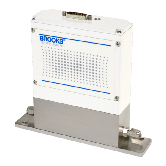
Summary of Contents for Brooks Instrument Quantim QMC Series
- Page 1 Installation & Operation Manual Quantim® QMC Series Mass Flow Controllers & Meters...
- Page 2 Read before proceeding! Brooks Instrument designs, manufactures and tests its products to meet many national and international standards. These products must be properly installed, operated and maintained to ensure they continue to operate within their normal specifications. The following instructions must be adhered to and integrated into your safety program when installing, operating and maintaining Brooks Instrument products.
- Page 3 Brooks Instrument Installation Manual Quantim QMC Quick Start Guide Step 2: Mounting the Quantim Step 1: Location/Orientation The instrument may be located anywhere in the process line, as long as the following conditions are met: • Before operation, you must be able to stop flow through the meter. During the zeroing procedure, flow must be stopped completely, and the flow meter sensor tube must be full of process fluid to achieve an accurate zero.
- Page 4 Brooks Instrument Installation Manual Quantim QMC Step 4: Zeroing Procedure Step 3: Electrical Connections NEMA 1 / IP40 Meter/Controller To assure measurement accuracy, the instrument must be zeroed to the operational installation conditions: • Apply power to instrument for approximately 45 minutes to D-Connector Functions Legends: reach a stable thermal condition prior to applying flow.
- Page 5 Fax (215) 362 3745 BrooksAm@BrooksInstrument.com PIN5 14 -2 7V dc PowerS ource A list of all Brooks Instrument locations and contact details can be found at www.BrooksInstrument.com 10 K PIN1 1 Brooks and Quantim are trademarks of Brooks Instrument, LLC.
-
Page 6: Table Of Contents
Brooks Instrument Installation Manual Quantim QMC Contents Quick Start Instructions Quick Start Instructions Location / Orientation and Mounting..........QS-1 Quick Start Instructions Electrical Connections, Zeroing and Operation ......QS-2 Quick Start Instructions Equipment Receipt and Return..........QS-2 Quick Start Instructions Warning and Caution ..............QS-3 Quick Start Instructions Connecting Alarm Output ............QS-3... - Page 7 Brooks Instrument Installation Manual Quantim QMC Contents Figures Figure Page Number Number Dimensional Drawing QMC IP40 ................4 Lay-In Dimensions Integral Valve ................4 Flow Direction Through the Quantim, as Indicated by the Arrow Engraved on the Meter/Controller Body.................. 8 Horizontal Inverted Installation ................
-
Page 8: Section 1 Introduction
Maintenance & Troubleshooting Back Cover Warranty, Local Sales/Service Contact Informatio The Quality System at Brooks Instrument conforms to the quality standards set forth in ISO 9001. This instruction manual is intended to provide the user with all the information necessary to install, operate and maintain the Quantim ®... -
Page 9: Performance Specifications
Brooks Instrument Installation Manual Quantim QMC Section 1 Introduction QMBC (Controller) QMBM (Meter) PERFORMANCE Tube Size: Nominal Flow Range Liquid (kg/hr): 0.15 0.78 7.97 0.19 1.30 13.50 Gas (kg/hr): 0.076 0.214 1.796 0.103 0.53 3.840 Gas (sccm) 1051 2955 24787... - Page 10 Brooks Instrument Installation Manual Quantim QMC Section 1 Introduction DIAGNOSTICS Status Lights: Status and Alarm LEDs Alarms: Mass Flow, Density, Volumetric Flow, Temperature, Slug Flow, Diagnostic Failure, Setpoint Deviation, Valve Drive ELECTRICAL Output Signal: Digital: RS485 S-Protocol (See RS485 Supplemental Manual – QMC for additional details)
-
Page 11: Dimensions
GG99/J INITIAL RELEASE PURPOSE OTHER THAN FOR EVALUATION, PROVIDED THAT, IF A CONTRACT IS AWARDED TO BROOKS INSTRUMENT LLC, AS A RESULT OF OR IN CONNECTION WITH THE SUBMISSION OF SUCH DATA, THE CUSTOMER SHALL HAVE THE RIGHT TO DUPLICATE, USE OR DISCLOSE THIS DATA TO THE EXTENT PROVIDED IN THE CONTRACT. -
Page 12: Section 2 Installation
If the packing case is damaged, the local carrier should be notified at once regarding their liability. A report should be submitted to Brooks Instrument. Visit the Brooks Instrument website at www.brooksinstrument.com/en/service-support Remove the envelope containing the packing list. Carefully remove the instrument from the packing case. -
Page 13: Transit Precautions
Brooks Instrument Installation Manual Quantim QMC Section 2 Installation Transit Precautions To safeguard against damage during transit, transport the instrument to the installation site in the same container used for transportation from the factory if circumstances permit. Fluid Connections General Mounting Practices Use good piping practices to minimize transmitting any torque or bend- ing loads onto the process connections on Quantim®. - Page 14 Brooks Instrument Installation Manual Quantim QMC Section 2 Installation Recommended installation procedures: All models should be mounted to a stable surface that is relatively free from mechanical shocks and mechanical vibration using the supplied mounting plate. Leave sufficient room for access to the electrical connections.
-
Page 15: Process Mounting
Brooks Instrument Installation Manual Quantim QMC Section 2 Installation Process Mounting Quantim® will function in any orientation if the Coriolis sensor and the control valve remain filled with process fluid. Entrapped gas in a liquid application and entrapped liquid in a gas application should be prevented as it may disturb the Coriolis sensor and the control valve. -
Page 16: Horizontal Right Side Up Installation
Brooks Instrument Installation Manual Quantim QMC Section 2 Installation topside of the pipe to limit the possibility of entrapped fluid collecting in the sensor, which can cause errors. (See Figure 2-3). Figure 2-3 Horizontal Right Side Up Installation Vertical Mounting If Quantim®... -
Page 17: Electrical Interfacing
Brooks Instrument Installation Manual Quantim QMC Section 2 Installation Electrical Interfacing Meter and Controller Flow Output (Pins 2, 4 and 10) Flow Output configuration is a factory selected option. Each Quantim® instrument is calibrated as either 0-5 (10) Vdc or (0) 4-20 mA at the factory as specified when ordering. - Page 18 Brooks Instrument Installation Manual Quantim QMC Section 2 Installation Secondary Outut, Density or Temperature (Pin 13 and Pin 10) Pin 13 indicates the density or temperature, represented by a (0) 4-20 mA or 0-5 (10) Vdc signal, proportional to density or temperature. The current and voltage signals are returned via Pin 10.
-
Page 19: General Wiring
Brooks Instrument Installation Manual Quantim QMC Section 2 Installation RS485 (S-Protocol) Communication Quantim® Model QMC is equipped with RS485 communication capability. Refer to Figure 2-1, D-Connector Electrical Pin Connections, that enables the device to communicate via a personal computer, PLC or DCS for process control. -
Page 20: Interconnection With Peripheral Equipment
Interconnection with Peripheral Equipment The following cables are available for connection of Quantim® Model QMC Me- ters and Controllers to the Brooks Instrument Microprocessor Control & Read- out Unit: Models # 0152, 0154, 0251 or 0254 Length: 3ft (1m); part number 124Y054AAA Length: 5ft (1.5m);... -
Page 21: Wire Color Codes For 'D' Connector Assembly
Brooks Instrument Installation Manual Quantim QMC Section 2 Installation Color Function Controller Meter Setpoint Common 0-5(10) Volt Flow Output (TTL) Open Collector Alarm Output (0)4-20 mA Flow Output Power Supply (14-27 V) Not Connected BLUE WHT/BLK (0)4-20 mA Setpoint Input... -
Page 22: Section 3 Operation
This condition can only be cleared by cycling power to the instrument. If the issue persists, call Technical Service at Brooks Instrument. Customer Service Brooks Technical Service is available to assist with start-up if you experience issues you cannot solve on your own. - Page 23 Brooks Instrument Installation Manual Quantim QMC Section 3 Operation After Quantim® has been fully installed, you must perform the zeroing procedure. This procedure ensures that the instrument responds properly to zero flow condition and sets a baseline for flow. To perform the zeroing operation on the meter/controller, use the ZERO button, which is located on top right hand side (outlet side) of the instrument.
-
Page 24: Calibration Procedure
Brooks Instrument Installation Manual Quantim QMC Section 3 Operation 4. After confirming that fluid flow through the instrument is completely stopped, actuate the zero function as previously stated. 5. The default zero sample interval is 30 seconds. A successful zero op- eration on the controller and meter will be indicated by a solid green color status LED. -
Page 25: General
Brooks Instrument Installation Manual Quantim QMC Section 4 Maintenance & Troubleshooting General There are no routine maintenance procedures required to keep your Quantim® instrument in good operating condition. It is however, very important to keep the fluid entering Quantim® clean, and as a result periodic replacement of the inlet guard filter is recommended at a frequency determined by the cleanliness of the fluid. -
Page 26: Troubleshooting
Brooks Instrument Installation Manual Quantim QMC Section 4 Maintenance & Troubleshooting Maintenance & Troubleshooting System Checks Quantim® Mass Flow Meters and Controllers are typically used as a critical component in fluid systems. These systems can be complex in nature and therefore isolating a malfunction has to be done with a system perspective. - Page 27 Valve out of adjustment. Adjust pressure to original Unstable inlet pressure. Contact Brooks Instrument. Defective PC board. Check external pressure regulator. Valves are tuned digitally and mechanically for a particular P. Contact Brooks Instrument.
- Page 28 Brooks Instrument Installation Manual Quantim QMC Section 4 Maintenance & Troubleshooting Table 4-1 Maintenance & Troubleshooting (continued) Observation Cause Resolution X-CM-QmC-eng/541B234AAG/2022-12...
- Page 29 Brooks Instrument Installation Manual Quantim QMC Section 4 Maintenance & Troubleshooting Bench Troubleshooting Quantim Bench Testing (Refer to Figure 4-1) Establish the proper electrical connection to the Quantim MFC/MFM. Do not connect the device to a fluid source yet. a. Connect a +14 Vdc to +27 Vdc power supply to Pin 5 and power supply common to Pin 9.
-
Page 30: Bench Troubleshooting Circuit
6. If the Quantim is functioning correctly, the problem may lie elsewhere in the flow system. Re-verify the installation as well as the upstream/ downstream fluid system configuration. 7. Please contact Brooks Instrument for further assistance visit our website www.brooksinstrument.com/en/service-support/ contact-techincal-services. - Page 31 Brooks Instrument can provide seminars and dedicated training to engineers, end users and maintenance persons. Please contact your nearest sales representative for more details. Due to Brooks Instrument's commitment to continuous improvement of our products, all specifications are subject to change without notice. TRADEMARKS Brooks is a trademark of Brooks Instrument, LLC All other trademarks are the property of their respective owners.
Need help?
Do you have a question about the Quantim QMC Series and is the answer not in the manual?
Questions and answers