Table of Contents
Advertisement
Quick Links
Advertisement
Table of Contents

Related Manuals for Brooks Instrument 0250 Series


Summary of Contents for Brooks Instrument 0250 Series
- Page 1 Installation & Operation Manual 0250 Series Secondary Electronics...
- Page 2 Read before proceeding! Brooks Instrument designs, manufactures and tests its products to meet many national and international standards. These products must be properly installed, operated and maintained to ensure they continue to operate within their normal specifications. The following instructions must be adhered to and integrated into your safety program when installing, operating and maintaining Brooks Instrument products.
-
Page 3: Table Of Contents
Brooks Instrument Contents Section 1 Introduction Description ..............................6 Architecture ..............................6 Communication ............................. 6 Process Controls ............................6 Operator Controls and Indicators ......................... 7 Diagnostic Capabilities ..........................7 Specifications (Reference Table 1-1) ......................7 Mounting Kit Options ............................ 9 Power Supply Options .......................... - Page 4 Brooks Instrument Contents Appendix A Engineering Units Available Engineering Units ......................44 Appendix B Blending Examples Examples 1 through 6 ........................45 Appendix C Serial Communications Protocol Overview................................. 46 RS232 Port Settings ............................46 Hyperterminal Set-Up ............................ 47 Command Structures ............................ 50 Command Addressing ..........................
- Page 5 2-4 Rack Installation ............................19 3-1 Home Screen............................20 3-2 Model 0251 - User Interface Screen Map ....................24 3-3 Model 0254 - User Interface Screen Map ....................25 Tables 1-1 Specifications - 0250 Series ........................8 3-1 Display Home Screen Fields ........................20...
-
Page 6: Description
Section 1 Introduction Brooks Instrument Description 0250 Series is a versatile full-featured measurement and control process instrument, available with single or multiple channel capabilities. The architecture supports a wide range of operating capabilities organized to meet the requirements of nearly any high-accuracy measurement and control application. -
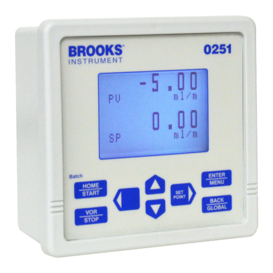
Page 7: Operator Controls And Indicators
The front panel key pad provides splash proofing and environment protection. The 0250 Series primary indicator is its large back lit liquid crystal graphic display - visible at a distance even in low light conditions - to view values, support programming operations, and indicate process state information. - Page 8 Brooks Instrument Section 1 Introduction Table 1-1 Specification - 0250 Series Performance Display 0251: 8 line x 20 character back-lit LCD display. 0254: 8 line x 40 character back-lit LCD display. Controls Keypad: 8-Key metal dome tactile push buttons with selectable audio beep for setpoint (rate, batch, blend), VOR, emergency stop, full operation and programming.
-
Page 9: Mounting Kit Options
Section 1 Introduction Mounting Kit Options The 0250 Series can be mounted using the following kits: Panel Mount Kit: Brackets accept panel thickness up to 0.25 in. (6.35 mm). Table Top Kit: Weighted base with fixed tilt for easy viewing. - Page 10 Brooks Instrument Section 1 Introduction Figure 1-1 Model 0251 Signal Wiring Figure 1-2 Model 0254 Signal Wiring Installation Manual 0250 Series...
-
Page 11: Section 2 Installation
Brooks Instrument Section 2 Installation General This section provides installation instructions for the 0250 Series Secondary Electronics device. Receipt of Equipment A Return Material Authorization (RMA) should be submitted to the nearest Brooks Instrument location via this page on our website: BrooksInstrument.com/Service... -
Page 12: Return Shipment
“as received.” Ventilation and Mounting Requirements Because of their low power consumption, the 0250 Series devices do not have ventilation requirements. However, the ambient temperature sur- rounding the 0251 Series devices should not exeed 122°F (50°C). The optional power supply modules are also ventilation-free and limited to an ambient temperature of 122°F (50°C). -
Page 13: Cable Requirements
Panel Mount Installation Instructions Cut a hole according to the cut-out dimensions shown in Figure 2-1. Pass the 0250 Series device enclosure through the cut-out. Position one of the two brackets included in the Panel Mount kit on the side of the enclosure, while aligning the two holes at the top and bottom of the bracket flange with the holes at the corners of the back of the enclosure. - Page 14 Brooks Instrument Section 2 Installation Model 0251 Model 0254 Figure 2-1 Panel Mount Cut-Out Dimensions Installation Manual 0250 Series...
-
Page 15: Tabletop Stand Assembly Instructions
Attach the four rubber mounting feet to the base, as shown in Figure 2-2. Use four of the provided screws to attach the two brackets to the base. Slide the 0250 Series device enclosure into the brackets. Use four screws to secure the enclosure to the brackets. CAUTION Do not over-tighten these attachment screws. - Page 16 Brooks Instrument Section 2 Installation Model 0251 Model 0254 Figure 2-2 Table Top Stand Mount Installation Installation Manual 0250 Series...
-
Page 17: Retrofit To Model 0152/0154 Tabletop Housing (Model 0254 Only)
Slide the enclosure into the box until the bezel is flush with the front of the box. Secure the bezel to the front of the box using the bezel screws. Connect the power supply AC cord to a power outlet. Installation Manual 0250 Series... -
Page 18: 19-In. Rack Assembly And Installation Instructions (Model 0254 Only)
19-in. Rack Assembly and Installation Instructions (Model 0254 only) Use these instructions whether you are installing the Model 0254 into your own rack or into the optional 19-in. rack assembly from Brooks Instrument. The optional 19-in. rack comes with a blind front plate covering half of the rack. - Page 19 Brooks Instrument Section 2 Installation Figure 2-3 Power Supply Bracket and Bezel Figure 2-4 Rack Installation Installation Manual 0250 Series...
-
Page 20: Home Screen
Brooks Instrument Section 2 Installation Home Screen The 0250 Series home screen is the instrument’s central information and navigation indicator. The home screen displays following initial power application, and automatically follows the make-model screen banner. It provides an overall view of the instrument’s operation. Table 3-1 below describes the main elements of the home screen. -
Page 21: Operating Controls
Quickly navigate to setpoint or valve override functions • Start and stop control functions • Select a blend control master • Execute the emergency stop function • Instructions for the using the above are described in their respective subsections throughout this section. Installation Manual 0250 Series... -
Page 22: Key Functions
Display Configuration Screen Zero PV Total when cursor points to PV Total. Program Screen Move blinking program selection to next left choice. All Screens: Selected Item Move cursor right. Home Screen HOT navigates to change channel setpoint value. Installation Manual 0250 Series... -
Page 23: Navigation
This screen shown is for Channel 2. Use the cursor keys to point to either Display Configuration to show the present PV Measurements and SP Status, or Instrument Configuration to program PV and SP values, and then press ENTER to proceed to the desired selection. Installation Manual 0250 Series... -
Page 24: User Interface Screen Map
Brooks Instrument Section 3 Operation User Interface Screen Map The Figures 3-2 and 3-3 show the screen mapping from the home page to the channel values. Figure 3-2 Model 0251 - User Interface Screen Map Installation Manual 0250 Series... - Page 25 Brooks Instrument Section 3 Operation Figure 3-3 Model 0254 - User Interface Screen Map Installation Manual 0250 Series...
-
Page 26: Process Values (Pv) And Setpoints (Sp)
The value displayed is updated in real time as the value changes. To clear an accumulated quantity to zero, point the cursor to PV Total and press the key. Note the value becomes zero. Installation Manual 0250 Series... -
Page 27: Pv-Sp Configuration
SP signal type and full-scale range • Channel service function • Channel override signal • SP values • SP programming source • The PV and SP values are static and are updated only after a value has been changed and saved. Installation Manual 0250 Series... -
Page 28: Value Programming
Setting the decimal has an arithmetic function that, when changed, automatically multiplies or divides an existing value so values continue to retain their power-of-ten value. The values so affected include PV and SP Full Scale, SP Rate, SP Batch. Installation Manual 0250 Series... - Page 29 This process is started using either the keypad or a serial communication command. Blending is terminated any time by pressing the STOP key from the home screen. Refer to “Blend Control” on p.38 for more details. Installation Manual 0250 Series...
- Page 30 SP Source This control enables selection of the source from which setpoints may be entered as either Keypad or Serial. When set for Serial, changing a set- point using the keypad is prohibited. Installation Manual 0250 Series...
-
Page 31: Global Settings
This is a factory-entered manufacturing serial number and does not relate directly to the device serial number. Version This is the date the firmware was last upgraded represented as year, month, and day, and is only for viewing. Installation Manual 0250 Series... -
Page 32: Global System Power
System Power. This will cause entry into the pow- er down state, the screen to become blank with its back-light off, and all signals and power to be removed from connected equipment. Power ON Press the START key to restore normal system operation. Installation Manual 0250 Series... -
Page 33: Global Control Services
Pwr SP Clear When this control is selected ON, power res- toration causes every channel SP value to be erased and made zero. Any VOR setting will be returned to normal. Installation Manual 0250 Series... -
Page 34: Global Communication
Position the cursor pointing towards the appropriate channel on the Home screen. Press the Enter/Menu key, and select Instrument Configuration by pressing the Enter/Menu key. Once in the Instrument Configuration screen, scroll down to the SP Function option and select Rate. Installation Manual 0250 Series... - Page 35 Setpoint hot key or the Instrument Configuration screen. Home Screen The delivery process can be monitored as shown on the real-time updated screens above and below. Observing that the SP Rate is the same as the monitored PV Rate. Installation Manual 0250 Series...
-
Page 36: Pv Configuration
Select Instrument Configuration by pressing the ENTER/MENU key. Once in the Instrument Configuration screen, scroll down to the PV Signal Type and PV Full Scale options and select the applicable PV Signal Type and PV Full Scale values that are desired. Installation Manual 0250 Series... -
Page 37: Batch Control
PV Rate properly indicates the desired delivery rate. The values in this screen are updated in real time. If the SP Function is set for Batch, the SP Batch quantity appears on this screen. Installation Manual 0250 Series... -
Page 38: Blend Control (Model 0254 Only)
Select a master channel and set its delivery SP Rate. One or more slave channels are then selected, and the process is started from the home screen. Once started, blending will continue and may ONLY be terminated by an operator. Installation Manual 0250 Series... -
Page 39: Blend Control Setup
5. Scroll down to the SP Rate option and input a zero flow rate setpoint (or via the Setpoint hot key). NOTE: If you input a flow rate setpoint other than zero, the Master Channel will immediately respond to that setpoint and will start to flow. Installation Manual 0250 Series... -
Page 40: Start Blend
SP Rate of the slave channels is the programmed proportion of the master rate. If desired, the Home screen can be reconfigured to replace SP Rate of the slave channels with SP Blend ratio, as described in “PV-SP Measures and Status” on p. 26. Installation Manual 0250 Series... -
Page 41: Terminate Blend In-Process
Once in the Instrument Configuration screen, scroll down to the SP VOR Function option and select the mode that is desired (Normal, Open, or Closed). The SP VOR selection can also be accessed directly by the VOR hot key. Installation Manual 0250 Series... -
Page 42: Totalization
Position the cursor pointing towards the appropriate channel on the Home screen. Press the ENTER/MENU key. Select Display Configuration by pressing the ENTER/MENU key. Once in the Display Configuration screen, scroll down and select the PV Total option. Installation Manual 0250 Series... -
Page 43: Emergency Off
To clear or reset an accumulated quantity to zero, point the cursor to PV Total and press the key. Note that the value is reset to zero. Emergency Off To shut down the instrument, press and hold the STOP/VOR button for three seconds. Installation Manual 0250 Series... -
Page 44: Available Engineering Units
Torr atm Volt mA oC oK oR oF g/cc lb/in^3 lb/ ft^3 lb/gal kg/m^3 g/ ml kg/l Note: “. ^3” means cubic “ . “ Installation Manual 0250 Series... -
Page 45: Appendix B Blending Examples
Blending ratio is = = 0.05 = 5% 1000 mbar Mass flow controller selections are: Master channel unit: 15 bar = Full Scale Value Slave channel unit: 20 l/min = Full Scale Value Blending ratio is = 50% Installation Manual 0250 Series... -
Page 46: Overview
The platform supports various com- munication facilities. Channels and Ports The 0250 Series is comprised of pairs of ports, each of which has an input and output to form a channel, with four channels total. Channel and port numbering... -
Page 47: Hyperterminal Set-Up
“Start->All Programs->Accessories->Communications- >Hyperterminal”. This shortcut will put up the screen shown below.” Enter a name for the connection and click the ‘OK’ button. In the next screen enter the right COM port number, see below. Installation Manual 0250 Series... - Page 48 Open the ‘File->Properties’ pull-down menu and click the ASCII Setup’ button and configure the settings as shown below. Dismiss both screens by clicking the OK button and enter the command ‘AZI’ to check if the connection was successful, as seen in the following screen. Installation Manual 0250 Series...
- Page 49 Brooks Instrument Appendix C Installation Manual 0250 Series...
-
Page 50: Command Structures
Sentinel indicating end of multiple packets message Transfer All messages are serial half-duplex send-response types. Baud Rate = 9600 Mastering The protocol initiator or originator is the master. The master is responsible for managing the communication link connection. Installation Manual 0250 Series... -
Page 51: Command Addressing
HOST SEND yyyyy <cr> + — message delim- iter +— command argument +— port sub-address +— unit address +— message prelimit- AZ[.xx]<argument><cr> Non-networked sub-addressed port AZ[yyyyy.xx]<argument><cr> Networked sub-addressed port RESPONSE - <argument> dependent Installation Manual 0250 Series... -
Page 52: General Commands
COMMANDS - Model 0254 V01.03.21 FD00 <cr><lf><lf> [M] Command Select Menu<cr><lf> Display Port Values<cr><lf> Send Measured<cr><lf> [I] Product Identify<cr><lf> [P] Program New Values<cr><lf> [Z] Clear Measured Values<cr><lf> [F] Batch Control Service<cr><lf> [B] Blend Control Service [G] Log Record Service Installation Manual 0250 Series... -
Page 53: View Programmed Channel Port Values
AZI<cr> Non-network AZ[yyyyy]I<cr> Network RESPONSE AZ,00000,4,BROOKS,0254,08,01.01.13,FE00,<sum><cr><lf> FIELDS Pre-limiter ,00000 Unit address Response type ,Brooks Instrument Make ,Model 0254 Model Port provision count ,V09.01.30 Code version date yy-mm- ,FE00 Start vector ,<sum> Negated mod256 sum <cr><lf> Delimiter Installation Manual 0250 Series... -
Page 54: Message Serial Character Pacing Controls
This command acts as an XOF to temporarily suspend unit from sending further characters: HOST SEND AZH<cr> Non-network AZ[yyyyy]H<cr> Network RESPONSE - none This command acts as an XON to allow or re-enable unit to continue sending characters: HOST SEND AZS<cr> Non-network AZ[yyyyy]S<cr> Network RESPONSE - none Installation Manual 0250 Series... -
Page 55: Serial Message Error Control
HOST SEND AZN<cr> Non-network AZ[yyyyy]N<cr> Network RESPONSE - none Installation Manual 0250 Series... -
Page 56: Measured Channel Values Command
Read Out device port number (input port channel 1) response type xxxxxxxx.xx Non resettable totalizer value 00162871.43 Totalizer value 0000003.27 process value … reserved parameters <sum> check sum <cr> carriage return character <If> l ine feed character Installation Manual 0250 Series... -
Page 57: Send Channel Input Port Programmed Values
Log Type <00> PV Signal Type 0-20mA <09> PV Full Scale 20.00 ml/m Each of the input port programmed operating values can be individually queried or changed in accordance with the procedures in Section C-5-1 and C-5-2. Installation Manual 0250 Series... -
Page 58: Program Channel Input Port Values
SP Batch 0.00 ml <45> SP Blend 0.000 % <46> SP Source Keypad Each of the port programmed operating values can be individually queried or changed in accordance with the procedures in Section C-5-1 and C-5-2. Installation Manual 0250 Series... -
Page 59: Batch And Blend Control Commands
[Batch] and [Batch Quantity] set greater than zero, with [Link] to the channel input port programmed to accumulate quantity. HOST SEND AZ F*<cr> start all channel batches AZ F<cr> stop all channel batches RESPONSE(S) AZ,[yyyyy.xx],5,FOK,DA,<cr><lf> batch started and in process AZ,[yyyyy.xx],5,FDONE,4E,<cr><lf> batch(s) completed AZ,[yyyyy.xx],5,FERROR,5D,<cr><lf> command error Installation Manual 0250 Series... - Page 60 The required master channel input port is specified in the start command by inserting its port sub-address [.xx] in the command, and must be one of the following: Channel Sub-Address HOST SEND AZ[.xx] B<cr> Start blending F<cr> Stop blend- RESPONSE - none Installation Manual 0250 Series...
-
Page 61: Global Setting Values
Section 3 using the <xx> value index. Communication Message Basics Messages between host and instrument are either polled (solicited) or un- polled (un-solicited), where the host is normally the polling (soliciting) party. Installation Manual 0250 Series... -
Page 62: Message Structure
MEASURE - channel input port values - sign convention as (+), space(+), or minus(-) ,xxx <reserved> ,QTY Quantity ,RATE Rate-Value ,xxx <reserved> ,xxx <reserved> CHECKSUM ,<sum> Negated mod256 sum PACKET DELIMITER <cr><lf> Packet end BLOCK DELIMITER <dle><etx> Block end Installation Manual 0250 Series... -
Page 63: Serial Value Programming
<present value> value of retrieved parameter <sum> check sum <cr> carriage return character <lf> line feed character The example below retrieves the setpoint, i.e. 20.00, for output port 8 channel 4 Request AZ.08P01?<cr> Response AZ,00909.08,4,P01,20.00,D- F<cr><if> Installation Manual 0250 Series... -
Page 64: Program A New Value
<new value> <sum> check sum <cr> carriage return character <lf> line feed character The example below configures the setpoint for output port 8 channel 4 to be 10.00. Request AZ.08P010.00<cr> Response AZ,00909.08,4,P01,10.00,D- F<cr><if> Installation Manual 0250 Series... -
Page 65: Channel Input Port Values
1 or 2 ascii chars with char range 0-2 not affecting proper operation 0 Off <reserved> 0-20mA 1 ascii char min 4-20mA 0-10V 2-10V 0-5V < 1-5V Excitation Type 1 ascii char optional <reserved> Measurement magnitude range Decimal Point xxx. 1 ascii char xx.x x.xx .xxx Installation Manual 0250 Series... - Page 66 1-7 ascii chars var dp Measurement per unit time relationship Rate Time Base 0 none (Scalar) 1 ascii char 1 sec 2 min 3 hrs 4 day Scale Factor by which interpolated channel units are multiplied 27 Gas Factor xxx.xxx 0 to ±999.999 1-7 ascii chars fix dp Installation Manual 0250 Series...
-
Page 67: Channel Output Port Values
0 to ±999.999 1-7 ascii char var Blend Mixing Set-Point SP Blend xxxxxx 0 to ±999.999 1-7 ascii char var dp (automatic % units) Set-Point Programming Source SP Source 1 ascii char 0 Keypad 1 Serial keypad prohibit Installation Manual 0250 Series... -
Page 68: Global Setting Values
Power Set-Points Clear - ON causes all channel set-points to become zero Pwr SP Clear 1 ascii char 0 Off 1 On Audio Annunciate Control - ON enables annunciate key activation and alarms Audio Beep 1 ascii char 0 Off 1 On Installation Manual 0250 Series... - Page 69 Brooks Instrument can provide seminars and dedicated training to engineers, end users and maintenance persons. Please contact your nearest sales representative for more details. Due to Brooks Instrument's commitment to continuous improvement of our products, all specifications are subject to change without notice. TRADEMARKS Brooks is a trademark of Brooks Instrument, LLC All other trademarks are the property of their respective owners.
Need help?
Do you have a question about the 0250 Series and is the answer not in the manual?
Questions and answers