
Related Manuals for Brooks Instrument 5860E


Summary of Contents for Brooks Instrument 5860E
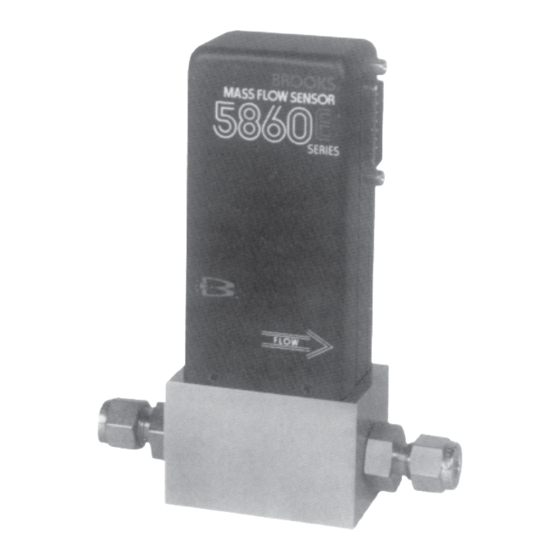
- Page 1 Installation and Operation Manual X-TMF-5860E-MFM-eng Part Number: 541B106AAG ® Brooks Model 5860E November, 2008 Model 5860E Mass Flow Meter...
- Page 2 Essential Instructions Read this page before proceeding! Brooks Instrument designs, manufactures and tests its products to meet many national and international standards. Because these instruments are sophisticated technical products, you must properly install, use and maintain them to ensure they continue to operate within their normal specifications.
- Page 3 We appreciate this opportunity to service your flow measurement and control requirements with a Brooks Instrument device. Every day, flow customers all over the world turn to Brooks Instrument for solutions to their gas and liquid low-flow applications. Brooks provides an array of flow measurement and control products for various industries from biopharmaceuticals, oil and gas, fuel cell research and chemicals, to medical devices, analytical instrumentation, semiconductor manufacturing, and more.
- Page 4 Installation and Operation Manual X-TMF-5860E-MFM-eng Part Number: 541B106AAG ® Brooks Model 5860E November, 2008 THIS PAGE WAS INTENTIONALLY LEFT BLANK...
-
Page 5: Table Of Contents
Contents Installation and Operation Manual X-TMF-5860E-MFM-eng Part Number: 541B106AAG Brooks ® Model 5860E November, 2008 Section 1 Introduction Paragraph Page Number Number Purpose ................1-1 Description ................ 1-1 Specifications ..............1-2 Section 2 Installation Receipt of Equipment ............2-1 Recommended Storage Practice ........2-1 Return Shipment .............. - Page 6 Recommended Filter Size ..........2-4 Bench Troubleshooting ............4-2 Sensor Troubleshooting ............. 4-2 Conversion Factors (Nitrogen Base) ........4-7 Model 5860E Standard Restrictors ........4-11 Model 5860E Replacement Parts List ........ 5-3 Tool and Spare Part Kits for 5860E ........5-3...
-
Page 7: Purpose
This instruction manual is intended to provide the user with all the information necessary to install, operate and maintain the Brooks 5860E Mass Flow Meter. This manual is organized into five sections: Section 1 - Introduction... -
Page 8: Specifications
Section 1 Introduction Installation and Operation Manual X-TMF-5860E-MFM-eng Part Number: 541B106AAG Brooks ® Model 5860E November, 2008 Figure 1-1 Typical Response to Flow Step Changes 1-3 Specifications Flow Ranges Any full scale flowrate from 3 sccm to 30 slpm, N *Standard temperature and pressure in accordance with SEMI (Semiconductor Equipment and Materials Institute) standard: 0°... - Page 9 Installation and Operation Manual X-TMF-5860E-MFM-eng Part Number: 541B106AAG ® Brooks Model 5860E November, 2008 Response Time Less than 3 seconds response to within 2% of full scale final value for a 0 to 100% command step. Control / Usable Range...
- Page 10 Section 1 Introduction Installation and Operation Manual X-TMF-5860E-MFM-eng Part Number: 541B106AAG Brooks ® Model 5860E November, 2008 THIS PAGE WAS INTENTIONALLY LEFT BLANK...
-
Page 11: Receipt Of Equipment
E-mail: BrooksEu@BrooksInstrument.com 2-2 Recommended Storage Practice If intermediate or long-term storage is required for equipment as supplied by Brooks Instrument, it is recommended that said equipment be stored in accordance with the following: a. Within the original shipping container. b. Store in a sheltered area with the following conditions: 1. -
Page 12: Return Shipment
Copies of the form can be obtained at one of the locations above. 2-4 Gas Connections Standard inlet and outlet connections supplied on the Model 5860E are 1/ 4" compression fittings for flow rates up to 10 slpm, and 3/8" compression fittings for higher flow rates. -
Page 13: Model 5860E Dimensions
1/4" Tube VCO 3.86 98.0 1/4" Tube VCR 4.18 106.2 3/8" Compression 4.44 Fitting 112.8 Figure 2-1 Model 5860E Dimensions PIN NO. FUNCTION COLOR CODE Cmd. Common (Command Pot "CCW") • Black 0-5 Volt Signal Output White Supply Common Valve Off •... -
Page 14: In-Line Filter
Plumbing should be checked carefully for leaks and the meter purged with dry Nitrogen before use. d. The Model 5860E Mass Flow Meter can be installed in any position. However mounting orientations other than the original factory calibration (see data sheet) will result in a ±0.5% maximum full scale shift after re-zeroing. - Page 15 Model 5860E. Avoid making connections marked in Figure 2-2 which are marked •. Also, the plug-in jumpers on the printed circuit board are not used by the Model 5860E and have no effect on performance. The following minimum electrical connections must be made for new...
- Page 16 Section 2 Installation Installation and Operation Manual X-TMF-5860E-MFM-eng Part Number: 541B106AAG Brooks ® Model 5860E November, 2008 THIS PAGE WAS INTENTIONALLY LEFT BLANK...
- Page 17 Model 5860E November, 2008 3-1 Theory of Operation The thermal mass flow sensing technique used in the 5860E works as follows: A precision power supply provides a constant power heat input (P) at the heater which is located at the midpoint of the sensor tube. (Refer to Figure 3-1) At zero or no flow conditions, the heat reaching each temperature sensor (one upstream and one downstream of the heater) is equal.
-
Page 18: Flow Sensor Operational Diagram
Adjust for the desired flow and assume normal operation. 3-3 Zero Adjustment Each Model 5860E is factory adjusted to provide a 0 ±10mVdc signal at zero flow. The adjustment is made in our calibration laboratory which is temperature controlled to 21.1°C (70°F ±2°F). After initial installation and warm-up in the gas system the zero flow indication may be other than the factory setting. - Page 19 November, 2008 3-4 Calibration Procedure NOTE 1: Calibration of the Model 5860E mass flowmeter requires the use of a digital voltmeter (DVM) a flow control valve or mass flow controller to set the flow rate and a precision flow standard calibrator such as the ®...
-
Page 20: Model 5860E Calibration Connections
Section 3 Operation Installation and Operation Manual X-TMF-5860E-MFM-eng Part Number: 541B106AAG Brooks ® Model 5860E November, 2008 Figure 3-2 Model 5860E Calibration Connections Figure 3-3 Adjustment Potentiometer Location Figure 3-4 Fast Response Adjustment... - Page 21 Installation and Operation Manual X-TMF-5860E-MFM-eng Part Number: 541B106AAG ® Brooks Model 5860E November, 2008 Example: What is the percent of full scale error when full scale is equal to 100 sccm? Measured flow rate = 50.0 sccm Indicated flow rate = 48.5 sccm h.
- Page 22 2 of D-Connector. TP4 may be used for ground. a. With the shut-off valve open adjust the metering valve so that the output voltage of the Model 5860E is 4.050 to 5.000 Vdc. Allow the output to become stable at this setting.
-
Page 23: Bench Troubleshooting
Brooks Model 5860E November, 2008 4-1 General No routine maintenance is required on the Model 5860E other than an occasional cleaning. If an in-line filter is used, the filtering element should periodically be replaced or ultrasonically cleaned. 4-2 Troubleshooting A. System Checks The Model 5860E is generally used as a component in gas handling systems which can be quite complex. - Page 24 Section 4 Maintenance Installation and Operation Manual X-TMF-5860E-MFM-eng Part Number: 541B106AAG Brooks ® Model 5860E November, 2008 Table 4-1 Bench Troubleshooting Trouble Possible Cause Check/Corrective Action Output stays at 0 Volts Clogged Sensor. Clean sensor. Refer to cleaning procedure. Section 4-4.
-
Page 25: Sensor Troubleshooting
Note: Do not attempt to disassemble the sensor. D. Cleaning Procedures Should the Model 5860E Mass Flow Meter require cleaning due to deposition, use the following procedures: 1. Remove the unit from the system. 2. Refer to Section 4-4 to disassemble the flowmeter. - Page 26 Refer to Section 3-4. 4-4 Disassembly and Assembly Note: The Model 5860E Mass Flow Meter may be disassembled and assembled in in the field by the user for cleaning, reranging or servicing. Disassemble and reassembly the meter as follows: A.
- Page 27 Installation and Operation Manual X-TMF-5860E-MFM-eng Part Number: 541B106AAG ® Brooks Model 5860E November, 2008 B. Assembly Note: It is recommended that all O-rings be replaced during flowmeter assembly. All O-rings should be lightly lubricated with Halocarbon lubricant (part of O-ring kit, Section 5) prior to their installation.
- Page 28 X-TMF-5860E-MFM-eng Part Number: 541B106AAG Brooks ® Model 5860E November, 2008 4-5 Use of the Conversion Tables If a mass flowmeter is operated on a gas other than the gas it was calibrated with, a scale shift will occur in the relationship between the output signal and the mass flow rate.
- Page 29 Section 4 Maintenance Installation and Operation Manual X-TMF-5860E-MFM-eng Part Number: 541B106AAG ® Brooks Model 5860E November, 2008 Table 4-3 Conversion Factors (Nitrogen Base) Ref. No. J836D508. GAS NAME FORMULA SENSOR ORIFICE DENSITY FACTOR FACTOR (kg/m Acetylene 0.615 0.970 1.173 Mixture 0.998...
- Page 30 Section 4 Maintenance Installation and Operation Manual X-TMF-5860E-MFM-eng Part Number: 541B106AAG ® Brooks Model 5860E November, 2008 Table 4-3 Conversion Factors (Nitrogen Base) Ref. No. J836D508 Continued. GAS NAME FORMULA SENSOR ORIFICE DENSITY FACTOR FACTOR (kg/m Hydrogen 1.008 0.269 0.090 Hydrogen Bromide 0.987...
- Page 31 115 mm water column pressure drop for a specific flow rate. This corresponds to the desired full scale flow rate. A list of restrictor assemblies used in the Model 5860E Series Mass Flowmeters is shown in Table 4-4.
- Page 32 Section 4 Maintenance Installation and Operation Manual X-TMF-5860E-MFM-eng Part Number: 541B106AAG Brooks ® Model 5860E November, 2008 Example: The desired gas is Silane (SiH The desired full scale flow rate is 200 sccm. Sensor conversion factor is 0.68 from Table 4-3.
- Page 33 Section 4 Maintenance Installation and Operation Manual X-TMF-5860E-MFM-eng Part Number: 541B106AAG ® Brooks Model 5860E November, 2008 Table 4-4 Model 5860E Standard Restrictors Range Part Number* sccm Air Equivalent Flow Size High Sintered ACLFE Wire Mesh 8.022 11.36 S110Z296 S110Z275 11.23...
- Page 34 Section 4 Maintenance Installation and Operation Manual X-TMF-5860E-MFM-eng Part Number: 541B106AAG Brooks ® Model 5860E November, 2008 THIS PAGE WAS INTENTIONALLY LEFT BLANK 4-12...
- Page 35 Section 5 Parts List Installation and Operation Manual X-TMF-5860E-MFM-eng Part Number: 541B106AAG ® Brooks Model 5860E November, 2008 5-1 General When ordering parts, please specify: Brooks Serial Number Model Number Part Description Part Number Quantity (Refer to Figure 5-1 and Tables 5-1 and 5-2).
-
Page 36: Model 5860E Parts Drawing
Section 5 Parts List Installation and Operation Manual X-TMF-5860E-MFM-eng Part Number: 541B106AAG Brooks ® Model 5860E November, 2008 Figure 5-1 Model 5860E Parts Drawing... - Page 37 50 Feet S124Z579AAA 8-32 Mounting Screw Customer Supplied ***QTA=Viton, SUA=Buna, TTA=Kalrez, AR=As Required, NS=Not Shown Table 5-2 Tool and Spare Part Kits for Model 5860E Model 5850 Service Tool Kit Model 5850 Break Out Board Assembly P/N S778D017AAA P/N S273Z668AAA...
- Page 38 Section 5 Parts List Installation and Operation Manual X-TMF-5860E-MFM-eng Part Number: 541B106AAG Brooks ® Model 5860E November, 2008 THIS PAGE WAS INTENTIONALLY LEFT BLANK...
- Page 39 CE mærkning af Masse Flow udstyr Dato Januar-1996. Brooks Instrument har gennemført CE mærkning af elektronisk udstyr med succes, i henhold til regulativet om elektrisk støj (EMC direktivet 89/336/EEC). Der skal dog gøres opmærksom på benyttelsen af signalkabler i forbindelse med CE mærkede udstyr.
- Page 40 Section A CE Certification Installation and Operation Manual X-TMF-5860E-MFM-eng Part Number: 541B106AAG Brooks ® Model 5860E November, 2008 English Brooks Instrument 407 West Vine St. Hatfield, PA 19440 U.S.A. Subject Addendum to the Instruction Manual. Reference CE certification of Mass Flow Equipment Date January-1996.
- Page 41 Section A CE Certification Installation and Operation Manual X-TMF-5860E-MFM-eng Part Number: 541B106AAG ® Brooks Model 5860E November, 2008 Français Brooks Instrument 407 West Vine St. Hatfield, PA 19440 U.S.A. Sujet Annexe au Manuel d’Instructions. Référence Certification CE des Débitmètres Massiques à Effet Thermique.
- Page 42 : Januari 1996 Dames en heren, Alle CE gemarkeerde elektrische en elektronische produkten van Brooks Instrument zijn met succes getest en voldoen aan de wetgeving voor Electro Magnetische Compatibiliteit (EMC wetgeving volgens 89/336/EEC). Speciale aandacht is echter vereist wanneer de signaalkabel gekozen wordt voor gebruik met CE gemarkeerde produkten.
- Page 43 Utførelse av signalkabel og tilhørende plugger: • Brooks Instrument tilbyr levert med utstyret egnet kabel som møter de krav som stilles til CE-sertifisering. • Dersom kunden selv velger kabel, må kabel med fullstendig, 100% skjerming av lederene benyttes.
- Page 44 Section A CE Certification Installation and Operation Manual X-TMF-5860E-MFM-eng Part Number: 541B106AAG Brooks ® Model 5860E November, 2008 Suomi Brooks Instrument 407 West Vine St. Hatfield, PA 19440 U.S.A. Asia : Lisäys Käyttöohjeisiin Viite : Massamäärämittareiden CE sertifiointi Päivämäärä : Tammikuu 1996 Brooksin CE merkillä...
- Page 45 Installation and Operation Manual X-TMF-5860E-MFM-eng Part Number: 541B106AAG ® Brooks Model 5860E November, 2008 THIS PAGE WAS INTENTIONALLY LEFT BLANK...
- Page 46 Within Netherlands 0318 549 290 Asia +011-81-3-5633-7100 Due to Brooks Instrument's commitment to continuous improvement of our products, all specifications are subject to change without notice. TRADEMARKS Brooks ............Brooks Instrument, LLC Freon TF .......... E. I. DuPont deNemours & Co.
Need help?
Do you have a question about the 5860E and is the answer not in the manual?
Questions and answers