
Related Manuals for Brooks Instrument 0154


Summary of Contents for Brooks Instrument 0154
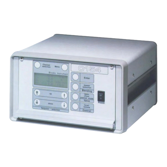
- Page 1 Installation and Operation Manual X-SE-0152-0154-eng Part Number: 541C052AAG ® Brooks Models 0152/0154 March, 2008 Gas and Liquid Mass Flow Secondary Electronics Brooks Model 0154 Four Channel Read Out Table Top Housing...
- Page 2 Essential Instructions Read this page before proceeding! Brooks Instrument designs, manufactures and tests its products to meet many national and international standards. Because these instruments are sophisticated technical products, you must properly install, use and maintain them to ensure they continue to operate within their normal specifications.
- Page 3 We appreciate this opportunity to service your flow measurement and control requirements with a Brooks Instrument device. Every day, flow customers all over the world turn to Brooks Instrument for solutions to their gas and liquid low-flow applications. Brooks provides an array of flow measurement and control products for various industries from biopharmaceuticals, oil and gas, fuel cell research and chemicals, to medical devices, analytical instrumentation, semiconductor manufacturing, and more.
- Page 4 Installation and Operation Manual X-SE-0152-0154-eng Part Number: 541C052AAG ® Brooks Models 0152/0154 March, 2008 THIS PAGE WAS INTENTIONALLY LEFT BLANK...
-
Page 5: Table Of Contents
Installation and Operation Manual Contents X-SE-0152-0154-eng Part Number: 541C052AAG Models 0152 / 0154 March, 2008 Paragraph Page Number Number Section 1 Introduction Description ............................1-1 Specifications ........................... 1-2 Optional Equipment .......................... 1-7 1-3-1 Connecting Flomega Series ......................1-7 1-3-2 Connecting Mass Flow and Pressure Series ..................1-7 1-3-3 Connecting Smart Series ......................... - Page 6 Figure Page Number Number Dimensions Table Top Models 0152/0154 ..................1-3 Dimensions Panel Mount Models 0152/0154 ................... 1-3 Dimensions of 1/2 19" Cassette ....................... 1-4 Mounting of 1/2 19" Cassette into 19" Rack ..................1-4 Mounting of Panel Mount Unit with Dimensions for the Panel Cut-Out ..........1-5 Electrical Configuration ........................
-
Page 7: Section 1 Introduction
This connector includes up to 4 channels with setpoint input and flowrate or pressure output. An RS-232 port is provided standard to control the 0152/0154 from a PC. This port enables connection of up to 4 analog (or analog configured devices) to a Model 0154. -
Page 8: Specifications
One 9-pin D connector for RS232 communication link to a PC. Display reading Model 0152: 2x 20 character and Model 0154: 4x 20 character display with back lighting. Percentage full scale or actual reading. Controls Membrane push buttons for setpoint, blending, valve override, local/ remote control, menu selection per channel and power switch. -
Page 9: Dimensions Table Top Models 0152/0154
Installation and Operation Manual Section 1 Introduction X-SE-0152-0154-eng Part Number: 541C052AAG ® Brooks Models 0152/0154 March, 2008 Figure 1-1 Dimensions Table Top Models 0152/0154 Figure 1-2 Dimensions Panel Mount Models 0152/0154... -
Page 10: Dimensions Of 1/2 19" Cassette
Installation and Operation Manual Section 1 Introduction X-SE-0152-0154-eng Part Number: 541C052AAG ® Brooks Models 0152/0154 March, 2008 All housing options consist of a standard 1/2 19" cassette ( 3HE x 42TE ) using three different parts: • Table Top Option: Table Top Housing •... -
Page 11: Mounting Of Panel Mount Unit With Dimensions For The Panel Cut-Out
Section 1 Introduction X-SE-0152-0154-eng Part Number: 541C052AAG ® Brooks Models 0152/0154 March, 2008 The panel mount option uses the cassette mounted into a panel using the panelmount bracket set. The dimensions for the panel cutout and the mounting details are:... - Page 12 Installation and Operation Manual Section 1 Introduction X-SE-0152-0154-eng Part Number: 541C052AAG ® Brooks Models 0152/0154 March, 2008 Figure 1-6 Electrical Configuration...
-
Page 13: Optional Equipment
Models 0152 or 0154, the following interconnecting cables are available: 1-3-1 Connecting Flomega Series For connecting the Models 0152 or 0154 to the Flomega series 5880 and 5890, the following cables are available: Length 3 m (9.84 ft); part number 124Z605ZZZ Length 6 m (19.69 ft);... -
Page 14: Connecting Quantim
Length: 10ft (3m); part number 124Z907ZZZ Length: 25ft (7m); part number 124Z908ZZZ Length: 50ft (15m); part number 124Z909ZZZ 1-3-5 RS-232 Communication For connecting the Model 0152/0154 to a personal computer an RS-232 cable is available: Length: 3 m (9.84 ft); part number 124Z901ZZZ Note: This cable is only required when using digital communication between Model 0152/0154 and a personal computer (see Section 4-1). -
Page 15: Section 2 Installation
This section provides installation instructions for the Brooks ® Models 0152 and 0154 Gas and Liquid Mass Flow Secondary Electronics devices. 2-2 Receipt of Equipment When the instrument is received, the outside packing case should be checked for damage incurred during shipment. If the packing case is damaged, the local carrier should be notified at once regarding his liability. -
Page 16: Return Shipment
E-mail: BrooksEu@EmersonProcess.com All flow instruments returned to Brooks requires completion of Form RPR003-1, Brooks Instrument Decontamination Statement, along with a Material Safety Data Sheet (MSDS) for the fluid(s) used in the instrument. Failure to provide this information will delay processing by Brooks personnel. -
Page 17: Ventilation And Mounting Requirements
X-SE-0152-0154-eng Part Number: 541C052AAG ® Brooks Models 0152/0154 March, 2008 2-7 Ventilation and Mounting Requirements The ventilation holes of the instrument must never be blocked or covered. When installing the instrument in a panel or a rack, always take care that proper ventilation is provided. -
Page 18: Connector Pinning
X-SE-0152-0154-eng Part Number: 541C052AAG ® Brooks Models 0152/0154 March, 2008 Two fuses are located in the power entry at the backside of the instrument. Remove the fuses by pulling out the fuse cartridge. The fuses must be replaced by fuses meeting the following requirements:... - Page 19 Installation and Operation Manual Section 2 Installation X-SE-0152-0154-eng Part Number: 541C052AAG ® Brooks Models 0152/0154 March, 2008 Table 2-1 Pinning of Channels 1 to 4 Connectors Input/ Function number Output Output +15Vdc/+24Vdc* Input Flow mA Output Setpoint mA Output Setpoint Volt...
- Page 20 Installation and Operation Manual Section 2 Installation X-SE-0152-0154-eng Part Number: 541C052AAG ® Brooks Models 0152/0154 March, 2008 Table 2-3 Pinning of Remote Connector Input/ Function Output number Output Flow Volt channel 1 Output Flow mA channel 1 Output Flow Volt channel 2...
-
Page 21: Jumper Settings And Functions
X-SE-0152-0154-eng Part Number: 541C052AAG ® Brooks Models 0152/0154 March, 2008 2-11 Jumper Settings and Functions As a standard, the required I/O selections are done at the factory upon ordering. When only 0-5 Vdc inputs and outputs are required, no optional I/O board has to be installed. -
Page 22: Adjustments Of Lcd Contrast And 5 V Reference
Installation and Operation Manual Section 2 Installation X-SE-0152-0154-eng Part Number: 541C052AAG ® Brooks Models 0152/0154 March, 2008 Table 2-6 Jumper Settings (Optional I/O Board Installed Input Jx01 Jx02 Jx03 Jx04 Jx06 Jx10 Jx11 Output 0-5 Vdc 0-10 Vdc 4(0)-20 mA... -
Page 23: Section 3 Operation
March, 2008 3-1 General The read-out function of the Models 0152 and 0154 and the controlling of the Mass Flow Controllers / Meters are designed for fast and easy usage. Basically, the flow output signals are shown on the display in percentage or in your own engineering units (full scale value and flow parameters can be adjusted per channel). - Page 24 Section 3 Operation X-SE-0152-0154-eng Part Number: 541C052AAG ® Brooks Models 0152/0154 March, 2008 Enter Confirmation key for confirmation of all changed settings. For example confirmation of selected setpoint value, master channel (blending), remote or local, valve function (valve control), certain menu selections, display layout or engineering unit.
-
Page 25: Start Up Screens
Section 3 Operation X-SE-0152-0154-eng Part Number: 541C052AAG ® Brooks Models 0152/0154 March, 2008 3-3 Start-Up Screens After power up, first the software version screen is displayed. This screen gives information about the software version currently installed. After a few seconds this screen is replaced by the flow information screen. -
Page 26: Changing The Setpoint Value
X-SE-0152-0154-eng Part Number: 541C052AAG ® Brooks Models 0152/0154 March, 2008 3-5 Changing the Setpoint Value If the setpoint value of a certain channel has to be changed, this channel has to be selected by the channel selection key first. After pushing one of the up and down keys, the display read-out of that channel changes from flow reading to the setpoint value. - Page 27 X-SE-0152-0154-eng Part Number: 541C052AAG ® Brooks Models 0152/0154 March, 2008 be active. All setpoints of the slave channel(s) remain as before power down, except the setpoint of the master channel(s). The setpoint of the master channel is determined in the “Start-up preferrence”...
-
Page 28: Using The Valve Control Function
Valve Override function is active again. The external Valve Control function can be used for overruling the internal 0152/0154 Valve Control funtion ( Valve Override open and close). Each channel can be controlled seperately. Valve Override open of the different channels can be activated externally by connecting one of the valve control inputs to resp. -
Page 29: Using The Remote Function
March, 2008 3-8 Using the Remote Function Every channel of the of the 0152/0154 can be placed in “remote” control. This means that the flow and setpoint signals can be read and controlled at remote distance e.g. in a control room. The local setpoint can be changed but does not have any impact on the connected controller as long as the controller is “Remote”... -
Page 30: Menu
Section 3 Operation X-SE-0152-0154-eng Part Number: 541C052AAG ® Brooks Models 0152/0154 March, 2008 3-9 Menu Pressing the Menu key will result in the menu screen on which the following menu selections can be activated: The remaining menu selections can be shown by scrolling through the screen with the up and down keys: The menu selection will be activated after confirmation with the Enter key. - Page 31 X-SE-0152-0154-eng Part Number: 541C052AAG ® Brooks Models 0152/0154 March, 2008 Full Scale Values The Full Scale Flow range is always 100.0 in case of using the default “%” as engineering unit. The Full Scale Value can not be changed in this case.
- Page 32 Section 3 Operation X-SE-0152-0154-eng Part Number: 541C052AAG ® Brooks Models 0152/0154 March, 2008 Totalizer Function and Display The totalizer display can be accessed by selecting “Totalizing” in the Menu (press the Menu button and use the up and down buttons to select).
- Page 33 Section 3 Operation X-SE-0152-0154-eng Part Number: 541C052AAG ® Brooks Models 0152/0154 March, 2008 Alarms Function and Display The alarm display can be accessed by selecting ‘Alarming’ in the Menu (press the Menu button and use the up and down buttons to select).
- Page 34 X-SE-0152-0154-eng Part Number: 541C052AAG ® Brooks Models 0152/0154 March, 2008 Set I/O Range and Range Selection Display The range selection display can be accessed by selecting ‘Set mA/Volts’ in the Menu (press the Menu button and use the up and down buttons to select).
-
Page 35: Section 4 Operation (Via Personal Computer)
Brooks has developed two executable software applications (Available is a TestPoint and LabView version, see Figures 11 and 12) for communication between Model 0152/0154 and a PC. For the LabView it is required to have a registered copy of LabView (the supplied file is a .LLB format) Both application versions handle the full capacity to control the connected devices. - Page 36 Installation and Operation Manual Section 4 Operation X-SE-0152-0154-eng (Via Personal Computer) Part Number: 541C052AAG ® Brooks Models 0152/0154 March, 2008 Figure 4-2 Testpoint...
-
Page 37: Appendix A Engineering Units
Installation and Operation Manual Appendix A Engineering Units X-SE-0152-0154-eng Part Number: 541C052AAG ® Brooks Models 0152/0154 March, 2008 A-1 Available Engineering Units ml/s g/min ml/min lb/s ml/h lb/min mls/s mls/min lb/h mls/h kg/s kg/min\ mln/s kg/h mln/min mln/hl/s ft^3/s l/min... - Page 38 Installation and Operation Manual Appendix A Engineering Units X-SE-0152-0154-eng Part Number: 541C052AAG ® Brooks Models 0152/0154 March, 2008 THIS PAGE WAS INTENTIONALLY LEFT BLANK...
- Page 39 Installation and Operation Manual Appendix B Blending Examples X-SE-0152-0154-eng Part Number: 541C052AAG ® Brooks Models 0152/0154 March, 2008 B-1 Blending Examples Example 1: Example 4: Master channel flow is 80 l/min Master channel flow is 100% Slave channel flow has to be 0.8 l/min...
- Page 40 Installation and Operation Manual Appendix B Blending Examples X-SE-0152-0154-eng Part Number: 541C052AAG ® Brooks Models 0152/0154 March, 2008 THIS PAGE WAS INTENTIONALLY LEFT BLANK...
- Page 41 CE mærkning af Masse Flow udstyr Dato Januar-1996. Brooks Instrument har gennemført CE mærkning af elektronisk udstyr med succes, i henhold til regulativet om elektrisk støj (EMC direktivet 89/336/EEC). Der skal dog gøres opmærksom på benyttelsen af signalkabler i forbindelse med CE mærkede udstyr.
- Page 42 Installation and Operation Manual Appendix C CE Certification X-SE-0152-0154-eng Part Number: 541C052AAG ® Brooks Models 0152/0154 March, 2008 English Brooks Instrument 407 West Vine St. Hatfield, PA 19440 U.S.A. Subject Addendum to the Instruction Manual. Reference CE certification of Mass Flow Equipment Date January-1996.
- Page 43 Installation and Operation Manual Appendix C CE Certification X-SE-0152-0154-eng Part Number: 541C052AAG ® Brooks Models 0152/0154 March, 2008 Français Brooks Instrument 407 West Vine St. Hatfield, PA 19440 U.S.A. Sujet Annexe au Manuel d’Instructions. Référence Certification CE des Débitmètres Massiques à Effet Thermique.
- Page 44 : Januari 1996 Dames en heren, Alle CE gemarkeerde elektrische en elektronische produkten van Brooks Instrument zijn met succes getest en voldoen aan de wetgeving voor Electro Magnetische Compatibiliteit (EMC wetgeving volgens 89/336/EEC). Speciale aandacht is echter vereist wanneer de signaalkabel gekozen wordt voor gebruik met CE gemarkeerde produkten.
-
Page 45: Appendix C Ce Certification
UTFØRELSE AV SIGNALKABEL OG TILHØRENDE PLUGGER: • Brooks Instrument tilbyr levert med utstyret egnet kabel som møter de krav som stilles til CE-sertifisering. • Dersom kunden selv velger kabel, må kabel med fullstendig, 100% skjerming av lederene benyttes. -
Page 46: Ce Certification Of Mass Flow Equipment
Installation and Operation Manual Appendix C CE Certification X-SE-0152-0154-eng Part Number: 541C052AAG ® Brooks Models 0152/0154 March, 2008 Suomi Brooks Instrument 407 West Vine St. Hatfield, PA 19440 U.S.A. Asia : Lisäys Käyttöohjeisiin Viite : Massamäärämittareiden CE sertifiointi Päivämäärä : Tammikuu 1996 Brooksin CE merkillä... - Page 47 Installation and Operation Manual X-SE-0152-0154-eng Part Number: 541C052AAG ® Brooks Models 0152/0154 March, 2008 THIS PAGE WAS INTENTIONALLY LEFT BLANK...
-
Page 48: Labview
Seller. BROOKS LOCAL AND WORLDWIDE SUPPORT Brooks Instrument provides sales and service facilities around the world, ensuring quick delivery from local stock, timely repairs and locally based sales and service facilities. Our dedicated flow experts provide consultation and support, assuring successful applications of the Brooks flow measurement and control products.
Need help?
Do you have a question about the 0154 and is the answer not in the manual?
Questions and answers