Table of Contents
Advertisement
Quick Links
Sho-Rate Series Models
1350G/1355G (Sizes 2-6)
Glass Tube Variable Area Flow Meters
Installation & Operation Manual
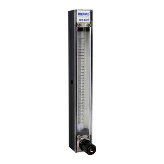
Sho-Rate
Model 1350G
(No Valve)
Sho-Rate
Model 1355G
(No Valve)
Sho-Rate
Model 1350G
with optional
integrated
flow controller
Sho-Rate
Model 1355G
with optional
integrated
flow controller
Sho-Rate
Model 1350G
with optional
needle valve
Sho-Rate
Model 1355G
with optional
needle valve
Advertisement
Table of Contents

Subscribe to Our Youtube Channel
Related Manuals for Brooks Instrument Sho-Rate Series


Summary of Contents for Brooks Instrument Sho-Rate Series
- Page 1 Sho-Rate Series Models 1350G/1355G (Sizes 2-6) Glass Tube Variable Area Flow Meters Installation & Operation Manual Sho-Rate Sho-Rate Sho-Rate Model 1350G Model 1350G Model 1350G (No Valve) with optional with optional integrated needle valve flow controller Sho-Rate Sho-Rate Sho-Rate Model 1355G...
- Page 2 Essential Instructions Read before proceeding! for local sales office contact information. Save this instruction manual for future reference. this warning can result in serious personal injury and / or damage to the equipment. result in serious personal injury and / or damage to the equipment. Connect all products to the proper electrical and pressure sources.
-
Page 3: Table Of Contents
Contents Section 1 Introduction Description ..............................1 Specifications ..............................1 Optional Equipment ............................4 Section 2 Installation General..............................5 Receipt of Equipment ..........................5 Unpacking ..............................5 Return Shipment ............................5 Recommended Storage Practice ........................ 5 Installation ..............................6 Section 3 Operation Operation .............................. - Page 4 Figures Typical Flowmeter Installation ........................7 Dimensions - Sho-Rate 1350G ........................ 7 Dimensions - Sho-Rate 1350G Panel Mount .................... .8 Dimensions - Sho-Rate 1350G Bezel ......................8 Dimensions - Sho-Rate 1355G Panel Mount .................... .9 Dimensions - Sho-Rate 1355G Bezel ....................... 10 Dimensions - Model 1350G/1355G with Flow Controller ................
-
Page 5: Section 1 Introduction
Section 1 Introduction Section 1: Introduction Description The Sho-Rate Flowmeters are variable area, glass tube, flow rate indicating meters. The basic elements are a tapered glass metering tube and a metering float. Features include quick and simple removal or installation of the tube and float while the meter remains in the process piping. -
Page 6: Specifications For Sho-Rate Models 1350G And 1355G
Section 1 Introduction Table 1-1 Specifications for Sho-Rate Models 1350G and 1355G Performance... -
Page 7: Tube And Float Code - Eighth And Ninth Digit In Model Code For Scale Configuration
Section 1 Introduction Table 1-2 Capacities - Rib Guide Tubes, Spherical Floats for use with 1350G Series Only Water Meter Tube Float SCFH NLPH Size Material Glass 0.010 0.041 0.12 Sapphire 0.021 0.079 0.19 R-2-65-A G Stainless Steel 0.049 0.18 0.37 Carboloy 0.10... -
Page 8: Optional Equipment
Section 1 Introduction Table 1-5 Capacities - Rib Guide Tubes, Spherical Floats for use with 1355G Series Only Meter Tube Float Maximum Flow Rate* Size Material Water (CC/Min) Glass 0.59 50 SCC/M Sapphire 79 SCC/M R-2-15-AAAA G Stainless Steel 150 SCC/M Carboloy 280 SCC/M Tantalum... -
Page 9: Section 2 Installation
Instrument must have been purged in accordance with the following: Recommended Storage Practice If intermediate or long term storage is required for equipment, as supplied by Brooks Instrument, it is recommended that said equipment be stored in accordance with the following: • Within the original shipping container. -
Page 10: Installation
Section 2 Installation Upon removal from storage, a visual inspection should be conducted to verify the condition of equipment is “as received”. If the equipment has been in storage for an excess of two (2) years or in conditions in excess of those recommended, all pressure boundary seals should be replaced and the device subject to a hydrostatic/pneumatic pressure test to 150% of rated pressure. -
Page 11: Typical Flowmeter Installation
Section 2 Installation HORIZONTAL VERTICAL LINE LINE FLOWMETER FLOWMETER A - Inlet Valve B - Outlet Valve C - Bypass Valve D - Control Valve E - Drain Valve Figure 2-1 Typical Flowmeter Installation It is recommended that a final leak test of the system plumbing and meter be performed before subjecting it to process fluid. -
Page 12: Dimensions - Sho-Rate 1350G Panel Mount
Section 2 Installation Figure 2-3 Dimensions - Sho-Rate 1350G Panel Mount Figure 2-4 Dimensions - Sho-Rate 1350G Bezel... -
Page 13: Dimensions - Sho-Rate 1355G Panel Mount
Section 2 Installation Figure 2-6 Dimensions - Sho-Rate 1355G Panel Mount... -
Page 14: Dimensions - Sho-Rate 1355G Bezel
Section 2 Installation Figure 2-7 Dimensions - Sho-Rate 1355G Bezel... -
Page 15: Dimensions - Model 1350G/1355G With Flow Controller
Section 2 Installation Figure 2-8 Dimensions - Model 1350G/1355G with Flow Controller... -
Page 16: Section 3 Operation Operation
Section 3 Operation Section 3: Operation After the flowmeter has been installed in the flow system, it is ready for operation. An optional built-in needle control valve may be provided to control the flow through the flowmeter. These control valves are designed for fine control. -
Page 17: Section 4 Bistable Inductive Limit Switches
Section 4: Bistable Inductive Limit Switches Description The Brooks bistable limit switches are inductive ring initiators designed to be slipped over the glass tube. The switch operates as a coil that is inductively actuated by a 316 Stainless Steel or Carboloy ball float. The limit switches can be set to any desired limit values, by sliding the switch along the metering tube. -
Page 18: Power Supply/Relay Unit
The power supply/relay unit must fulfill NAMUR requirement, EN 50227 (DIN 19234). Maximum operating temperature The maximum fluid temperature for the Sho-Rate series with the inductive switches is 70°C. Recommended spares Model... -
Page 19: Alarm Settings
Section 5: Alarm Settings Alarm Settings The minimum setting distance of a switch and a fitting is 8 mm, and the minimum setting distance between 2 switches is approx. 30 mm, see figure 1. The standard alarm function is a bistable (latching) function, see figure 2. Once the ball float moves inside the inductive switch, the alarm function is activated, it remains activited, even if the float continues to move towards the alarm zone, thus leaving the inductive switch. -
Page 20: Section 6 Maintenance
Section 6 Maintenance Section 6: Maintenance Disassembly and Cleaning It is recommended the user periodically inspect the tube and float, and clean if necessary. Dirt or foreign materials adhering to the tube and float may cause inaccuracy and sticking of the float. The metering tube (Borosilicate glass) and related parts may be cleaned with any solvent which does not attack glass. -
Page 21: Reassembly Procedure
Section 6 Maintenance Reassembly Procedure 1. Use the reverse of Steps 1 through 5 of the disassembly procedure to reassemble the meter. 2. Prior to installing the needle control valve assembly make certain that the valve stem is turned completely counterclockwise (full open position) to prevent damage to the valve seat. -
Page 22: General
Section 7 Parts List Section 7: Parts List General When ordering parts please specify: Brooks Serial Number Model Number Part Number Description and Quantity (Refer to Figure 5-1 and Table 5-1) -
Page 23: Parts Drawing Sho-Rate Models 1350G And 1355G
Section 7 Parts List Figure 7-1 Parts Drawing Sho-Rate Models 1350G and 1355G... - Page 24 Section 7 Parts List Table 7-1 Sho-Rate 1350G/1355G Parts List COMPONENT PART NUMBER for PART DESCRIPTION QTY. 1350G 1355G SEAL END FITTING Brass 325A110GGJ 325A110GGJ SS/STEEL Std Mat'l 325A109BMA 325A109BMA JACK PLUG Std Mat'l 817A088BMA 817A088BMA O RING (Jack Plug) Viton 375B012QTA 375B012QTA...
- Page 25 Section 7 Parts List Table 7-1 Sho-Rate 1350G/1355G Parts List (Continued) COMPONENT PART NUMBER for PART DESCRIPTION QTY. 1350G 1355G ADAPTERS from End Fitting ( to 5/16-24 UNF ) **2 if no FCA, 1 if with FCA 2 or 1 NO PART NO PART NONE (integral 5/16-24 UNF Thds)
- Page 26 Section 7 Parts List Table 7-1 Sho-Rate 1350G/1355G Parts List (Continued) COMPONENT PART NUMBER for PART DESCRIPTION QTY. 1350G 1355G 20 INLET FLOAT STOP R-2-65-AG,BG,CG Std Teflon 846B141QMA R-2-65-DG Std Teflon 846B144QMA R-6-65-AG Std Teflon 846B147QMA R-6-65-BG Std Teflon 846B150QMA R-2-15AAAAG,AG,DG Std Teflon 846B143QMA...
- Page 27 Section 7 Parts List Table 7-1 Sho-Rate 1350G/1355G Parts List (Continued) COMPONENT PART NUMBER for PART DESCRIPTION 1350G 1355G QTY. ADAPTER: Flow Controller to Cust Connection (1/4" M-NPT to) 1/8" (F) NPT 315T050BMA 315T050BMA 1/4" (F) NPT NO PART NO PART 1/8"...
- Page 28 Section 7 Parts List Table 7-1 Sho-Rate 1350G/1355G Parts List (Continued) VALVE O-RING MATERIAL TYPE SIZE BUNA VITON KALREZ EPR/EPM KALREZ/TEFLON BUTYL 947N091BMA 947N092BMA 947N095BMA 947N094BMA 947N096BMA 947N093BMA CARTRIDGE 3 947N097BMA 947N098BMA 947N101BMA 947N100BMA 947N102BMA 947N099BMA HIGH 947N103BMA 947N104BMA 947N107BMA 947N106BMA 947N108BMA 947N105BMA...
- Page 29 Section 7 Parts List Table 7-1 Sho-Rate 1350G/1355G Parts List (Continued) Sho-Rate G Valve Sizing - AIR Sho-Rate G Valve Sizing - WATER Recommended Recommended Recommended Recommended Max Flow (SCCM Max Flow (GPH Tube/Float Valve (CART) (10 Valve (NRS) Tube/Float Valve (CART) (10 Valve (NRS) Air @ STP) Sho-...
- Page 30 Brooks Instrument can provide seminars and dedicated training to engineers, end users and maintenance persons. Please contact your nearest sales representative for more details. Due to Brooks Instrument's commitment to continuous improvement of our products, all specifications are subject to change without notice. TRADEMARKS Brooks, Sho-Rate and NRS are trademarks of Brooks Instrument, LLC All other trademarks are the property of their respective owners.
Need help?
Do you have a question about the Sho-Rate Series and is the answer not in the manual?
Questions and answers