Bender ISOMETER isoRW425 Manual
Insulation monitoring device for unearthed it ac-, ac/dc and dc systems
Hide thumbs
Also See for ISOMETER isoRW425:
- Manual (72 pages) ,
- Quick start manual (13 pages) ,
- Quick start manual (12 pages)
Table of Contents

Related Manuals for Bender ISOMETER isoRW425


Summary of Contents for Bender ISOMETER isoRW425
- Page 1 Manual ISOMETER® isoRW425 Insulation monitoring device for unearthed IT AC-, AC/DC and DC systems (IT systems) for railway applications up to 3(N)AC, AC/DC 400 V Software version: D418 V2.xx isoRW425_D00052_03_M_XXEN / 02.2017...
- Page 2 Postbox 1161 • 35301 Gruenberg • Germany Tel.: +49 6401 807-0 Fax: +49 6401 807-259 E-Mail: info@bender.de Web: http://www.bender.de © Bender GmbH & Co. KG All rights reserved. Reprinting only with permission of the publisher. Subject to change! Photos: Bender archives and bendersystembau archives.
-
Page 3: Table Of Contents
Table of contents 1. Important information ..................7 How to use this manual ................. 7 Technical support: Service and support ..........8 1.2.1 First level support ..................... 8 1.2.2 Repair service ..................... 8 1.2.3 Field service ......................8 Training courses ....................9 Delivery conditions .................. - Page 4 Inhaltsverzeichnis 3.2.10 External, combined test or reset button T/R ........22 3.2.11 Fault memory ....................22 3.2.12 History memory HiS ..................23 3.2.13 Interface/protocols ..................23 4. Installation, connection and commissioning ........... 25 Installation ....................... 25 Connection ...................... 27 Commissioning ....................30 5.
- Page 5 Inhaltsverzeichnis 7.2.2 ISOMETER® answer to the master ............46 Exception code ....................47 7.3.1 Structure of the exception code .............. 47 8. Modbus register assignment of the ISOMETER® ........48 Device-specific data type of the ISOMETER® ........56 8.1.1 Device name ....................56 8.1.2 Measuring values ...................
-
Page 7: Important Information
1. Important information 1.1 How to use this manual Always keep this manual within easy reach for future reference. To make it easier for you to understand and revisit certain sections in this man- ual, we have used symbols to identify important instructions and information. The meaning of these symbols is explained below: This signal word indicates that there is a high risk of danger that will result in death or serious injury if not avoided. -
Page 8: Technical Support: Service And Support
Important information 1.2 Technical support: Service and support For commissioning and troubleshooting Bender offers you: 1.2.1 First level support Technical support by phone or e-mail for all Bender products Questions concerning specific customer applications Commissioning Troubleshooting ... -
Page 9: Training Courses
ZVEI (Zentralverband Elektrotechnik- und Elektronikindus- trie e.V.) (German Electrical and Electronic Manufacturers' Association) also applies. Sale and delivery conditions can be obtained from Bender in printed or elec- tronic format. 1.5 Inspection, transport and storage Inspect the dispatch and equipment packaging for damage, and compare the contents of the package with the delivery documents. -
Page 10: Warranty And Liability
Important information The devices must only be stored in areas where they are protected from dust, damp, and spray and dripping water, and in which the specified storage tem- peratures can be ensured. 1.6 Warranty and liability Warranty and liability claims in the event of injury to persons or damage to property are excluded if they can be attributed to one or more of the follow- ing causes: Improper use of the device. - Page 11 13th August 2005 must be taken back by the manufacturer and disposed of prop- erly. For more information on the disposal of Bender devices, refer to our homepage at www.bender.de -> Service & support. isoRW425_D00052_03_M_XXEN / 02.2017...
-
Page 12: Safety Instructions
2. Safety instructions 2.1 General safety instructions Part of the device documentation in addition to this manual is the enclosed "Safety instructions for Bender products". 2.2 Work activities on electrical installations Only skilled persons are permitted to carry out the work necessary to install, commission and run a de- vice or system. -
Page 13: Intended Use
Safety instructions 2.3 Intended use The ISOMETER® monitors the insulation resistance (R mode) or the insulation impedance (Z mode) of unearthed AC/DC main circuits (IT systems) with nom- inal system voltages of 3(N)AC, AC, AC/DC or DC 0 … 400 V. DC components existing in 3(N)AC, AC/DC systems do not influence the operating characteris- tics, when a minimum load current of DC 10 mA flows. -
Page 14: Function
RS-485 (galvanically isolated) including the following protocols: – BMS interface (Bender measuring device interface) for data exchange with other Bender components – Modbus RTU – IsoData (for continuous data output) Password protection to prevent unauthorised parameter changes ... -
Page 15: Functional Description
Function 3.2 Functional description The ISOMETER® measures the insulation resistance R and the leakage capac- itance C between the system to be monitored (L1/+, L2/-) and earth (PE). Z mode (selectable in the "SEt" menu) calculates the insulation impedance Z from R and C with a system frequency parameter f... -
Page 16: Monitoring Of The Insulation Resistance (R Mode)
Function If the values R or U do not exceed their release value (response value plus hysteresis) for the period t without interruption, the alarm relays will switch back to their initial position and the alarm LEDs AL1/ AL2 stop lighting. If the fault memory is activated, the alarm relays remain in alarm condition and the LEDs light until the reset button "R"... -
Page 17: Undervoltage/Overvoltage Monitoring
Function The lower resistance component of R or X determines the amount of Z . The higher resistance component of R or X can have a higher tolerance due to the measuring signal resolution. If the insulation impedance Z reaches or falls below the activated values Z1 or Z2, an alarm message will be signalled. - Page 18 Function Error codes If, contrary to expectations, a device error should occur, error codes will ap- pear on the display. Some of these are described below: Error code Meaning PE connection error The connections E or KE to earth are interrupted. E.01 Action: Check connection, eliminate error.
- Page 19 Function After eliminating the fault, the alarm relays switch back automatically or they return to the initial position by pressing the reset button. The self test can take a few minutes. It can be suppressed for the duration of the device start by setting the parameter in the menu "SEt" to "S.Ct = off".
-
Page 20: Malfunction
LEDs ON/AL1/AL2 will flash. If the error occurs again after restarting the device or after a reset to factory settings, then contact Bender Service. 3.2.6 Assignment of the alarm relays K1/K2... - Page 21 Function The measuring pulse is produced by the measuring pulse generator integrat- ed in the ISOMETER® . The measuring times for C and R % are syn- chronous. System disturbances may lead to extended measuring times. In contrast, the time for the system voltage measurement U is independent and considerably shorter.
-
Page 22: Password Protection (On, Off)
Function An alarm will continuously be signalled until the threshold value of the re- spective measuring value is not violated (including hysteresis) for the period of t without interruption. Each time the threshold value is not violated for the period of t , the delay-on release t restarts once again. -
Page 23: History Memory His
The ISOMETER® uses the serial hardware interface RS-485 with the following protocols: The BMS protocol is an essential component of the Bender measuring device interface (BMS bus protocol). ASCII characters are used for the data transfer. Modbus RTU ... - Page 24 Function With "Adr = 0", the menu entries baud rate and parity are not shown in the menu and the IsoData protocol is activated. With a valid bus address (i.e. not equal to 0), the menu item "baud rate" is displayed in the menu. The parameter value "---"...
-
Page 25: Installation, Connection And Commissioning
4. Installation, connection and commissioning Risk of electric shock! Touching uninsulated live conductors can result in death or serious injury. Therefore avoid any physical contact with active conductors and ensure compliance with the DANGER regulations for working on electrical installations. If the ISOMETER®... - Page 26 Installation, connection and commissioning 36 mm The front plate cover can be opened at the lower part marked with an arrow. isoRW425_D00052_03_M_XXEN / 02.2017...
-
Page 27: Connection
Installation, connection and commissioning 4.2 Connection Connect the terminals A1 and A2 to the supply voltage according to IEC 60364-4-43, i.e. the connections are to be protected against short-circuit by means of a protective device (a 6 A fuse is recommended). Devices for protection against short-circuit in conformity with IEC 60364-4-43 for the coupling of terminals L1/L2 to the IT system to be monitored can be omitted if the wiring is carried out in such a manner as to reduce the risk of a... - Page 28 Installation, connection and commissioning Connect the device as illustrated in the wiring diagram: L1/+ L2/- L1/+ COM460IP Test / Reset isoRW425 RS-485 isoRW425_D00052_03_M_XXEN / 02.2017...
- Page 29 Installation, connection and commissioning For details about the conductor cross sections required for wiring, refer to the technical data on Page 67. Wiring diagram legend: Terminal Connections Connection to the supply voltage via fuse (line protection). A1, A2 If supplied from an IT system, both lines have to be protected by a fuse.
-
Page 30: Commissioning
Installation, connection and commissioning 4.3 Commissioning 1. Check that the ISOMETER® is properly connected to the system to be monitored. 2. Connect the supply voltage to the ISOMETER® The device carries out a calibration, a self test and adjusts itself to the IT system to be monitored. -
Page 31: Device Operation
5. Device operation The menu structure is illustrated schematically on the following pages. After pressing the "MENU" button for > 1.5 seconds, the first menu item "AL" appears. Use (Enter) buttons for navigation and settings. Up and down button: - to navigate up or down the menu settings - increasing or decreasing values Pressing the MENU/Enter button for more than 1.5 s:... -
Page 32: Display Elements In Use
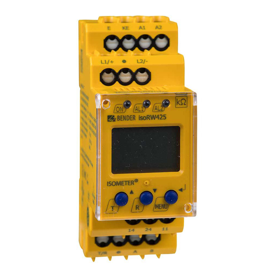
Device operation 5.1 Display elements in use Device front/display Function green - on Assignment according to yellow - alarm table on Page 35 yellow - alarm AL1 AL2 Up button Test button ( press > 1.5 s) Down button Reset button (press > 1.5 s) ENTER MENU button (press >... -
Page 33: Menu Structure
Device operation 5.2 Menu structure Measurement display Standard display Menu selection Menu Enter t > 5 min. Z [kΩ] Enter R [kΩ] C [μF] Parameter selection U L1 L2 [ V] UL1 [ V] UL2 [ V] . . . R [ %] U R [kΩ] Enter... -
Page 34: Menu "Al
Device operation 5.3 Menu "AL" 5.3.1 Response value setting Only after activating Z mode in the "SEt" menu, the response values Z1 as well as Z2 appear on the display and are activated. Simultaneously, the response values R1 and R2 are set to position off, but can then be set to on again. Display Activation Setting value Description... -
Page 35: Menu "Out
Device operation 5.4 Menu "out" 5.4.1 Configuration of the relay operating mode Relay K1 Relay K2 Description Display Display Operating mode of n.c. n.c. the relay n.c./n.o. FAC = Factory setting; Cs = User settings 5.4.2 Relay alarm assignment "r1" and "r2" and LED assignment In the alarm assignment, each alarm is assigned to the corresponding relay with the setting "on". - Page 36 Device operation Alarm K1 "r1" K2 "r2" LEDs description Display Display ON AL1 AL2 Alarm +R2 < Ω Fault R at L1/+ +R2 <Ω Alarm -R2 < Ω Fault R at L2/- -R2 < Ω ...
-
Page 37: Fault Memory Configuration
Device operation 5.4.3 Fault memory configuration Display Description Memory function for alarm messages (fault memory) FAC = Factory setting; Cs = User settings 5.4.4 Interface configuration Display Setting value Description Range Adr = 0 deactivates BMS as well as Modbus and Bus- 0 / 3 …... -
Page 38: Menu "T
Device operation 5.5 Menu "t" 5.5.1 Time configuration Display Setting value Description Alarm assignment 0 … 10 s Start-up time when starting the device 0 … 99 s Response delay K1 and K2 toff 0 … 99 s Delay on release K1 and K2 OFF / 1 / 24 test h Repetition time device test... -
Page 39: Menu "Set
60.0 50.0 ated system fre- quency f Test the system connec- tion during device test S.Ct Device test during device start Restore factory settings For Bender Service only FAC = Factory setting; Cs = User settings isoRW425_D00052_03_M_XXEN / 02.2017... -
Page 40: Measuring Value Display And History Memory
Device operation 5.7 Measuring value display and history memory In R mode only R and in Z mode only Z is permanently shown on the display (standard display). All other measuring value displays switch to the standard display after a maximum of 5 minutes. The fault location will only be stored in the history memory (HiS) in R mode. - Page 41 Device operation Display Description Fault location in % -100% …+100% Indication only from U ≥ 20 V ± R = (200% * R ) / (100% + x%) = (200% * R ) / (100% - x%) Insulation resistance 1 kΩ...
- Page 42 Device operation isoRW425_D00052_03_M_XXEN / 02.2017...
-
Page 43: Data Access Using The Bms Protocol
6. Data access using the BMS protocol The BMS protocol is an essential component of the Bender measuring device interface (BMS bus protocol). ASCII characters are used for the data transfer. BMS channel Operation value Alarm Pre-alarm R1 Alarm R2... -
Page 44: Data Access Using The Modbus Rtu Protocol
7. Data access using the Modbus RTU protocol Requests to the ISOMETER® can be made using the function code 0x03 (read multiple registers) or the command 0x10 (write multiple registers). The ISOMETER® generates a function-related answer and sends it back. 7.1 Reading out the Modbus register from the ISOMETER®... -
Page 45: Command Of The Master To The Isometer
Data access using the Modbus RTU protocol 7.1.2 Answer of the ISOMETER® to the master Byte Name Example Byte 0 ISOMETER® Modbus address 0x03 Byte 1 Function code 0x03 Byte 2 Number of data bytes 0x02 Byte 3, 4 Data 0x0047 Byte 7, 8 CRC16 Checksum... -
Page 46: Isometer® Answer To The Master
Data access using the Modbus RTU protocol 7.2.2 ISOMETER® answer to the master Byte Name Example Byte 0 ISOMETER® Modbus address 0x03 Byte 1 Function code 0x10 Byte 2, 3 Start register 0x0BBB Byte 4, 5 Number of registers 0x0001 Byte 6, 7 CRC16 Checksum 0x722A... -
Page 47: Exception Code
Data access using the Modbus RTU protocol 7.3 Exception code If a request cannot be answered for whatever reason, the ISOMETER® will send a so-called exception code with which possible faults can be narrowed down. Exception Description code 0x01 Impermissible function 0x02 Impermissible data access 0x03... -
Page 48: Modbus Register Assignment Of The Isometer
8. Modbus register assignment of the ISOMETER® The information in the registers is: the measuring value without alarm; the measuring value with alarm 1; the measuring value with alarm 2; or only the device fault, depending on the device condition. Measuring value Device Register... - Page 49 Modbus register assignment of the ISOMETER® Measuring value Device Register fault Without Alarm 1 Alarm 2 alarm 1012 System leakage 1015 capacitance (82) [no alarm] 1016 Voltage (76) [no alarm] 1019 1020 Voltage (76) [no alarm] 1023 Fault loca- 1024 tion in % 1027...
- Page 50 Modbus register assignment of the ISOMETER® Measuring value Device Register fault Without Alarm 1 Alarm 2 alarm Actual meas- 1032 urement --- Device (1022) [no fault (115) 1035 alarm] [device fault ( ) = Channel description code (refer to Chapter 8.2 ) [ ] = Alarm type (refer to Chapter 8.1.2.2 ) Permissi Description...
- Page 51 Modbus register assignment of the ISOMETER® Permissi Description Format Unit Value range Register Activation Pre-alarm value 0 = Inactive 3004 UINT 16 resistance 1 = Active measurement "R1" Pre-alarm value 3005 resistance UINT 16 kΩ R2 … 990 measurement "R1" Activation alarm value 0 = Inactive...
- Page 52 Modbus register assignment of the ISOMETER® Permissi Description Format Unit Value range Register Alarm value 3011 Overvoltage UINT 16 U< … 500 "U >" Memory func- tion for alarm 0 = Inactive 3012 messages UINT 16 1 = Active (Fault memory) "M"...
- Page 53 Modbus register assignment of the ISOMETER® Permissi Description Format Unit Value range Register Start-up delay "t" 3018 during device UINT 16 0 …10 start Response delay 3019 "ton" for relays UINT 16 0 … 99 K1 and K2 Delay on release 3020 "toff"...
- Page 54 Modbus register assignment of the ISOMETER® Permissi Description Format Unit Value range Register Device test dur- 0 = Inactive 3025 ing device start UINT 16 1 = Active "S. Ct" Request stop mode (0 = deac- 0 = Stop 3026 UINT 16 tivate device) 1 = ---...
- Page 55 Modbus register assignment of the ISOMETER® Permissi Description Format Unit Value range Register Software version Software 9821 UINT 16 number version Software 9822 UINT 16 version: Year Software 9823 UINT 16 version: Month Software 9824 UINT 16 version: Day Modbus driver 9825 UINT 16 version...
-
Page 56: Device-Specific Data Type Of The Isometer
Modbus register assignment of the ISOMETER® 8.1 Device-specific data type of the ISOMETER® 8.1.1 Device name The data format of the device name is specified below. Word 0x01 0x02 0x03 ------------------- 0x08 0x09 0x00 10 Words in total Each Word contains two ASCII characters 8.1.2 Measuring values Each measuring value is available as a channel and consists of 8 bytes (4 reg-... -
Page 57: Float = Floating Point Value Of The Channels
Modbus register assignment of the ISOMETER® 8.1.2.1 Float = Floating point value of the channels 0x00 0x01 HiByte LoByte HiByte LoByte S E E E E E E E E M M M M M M M M M M M M M M M M M M M M M M M Presentation of the bit order for processing analogue measuring values ac- cording to IEEE 754 S = Sign... -
Page 58: At&T = Alarm Type And Test Type (Internal/External)
Modbus register assignment of the ISOMETER® 8.1.2.2 AT&T = Alarm type and test type (internal/external) Meaning No alarm Prewarning Device error Reserved Warning Alarm Reserved … … … Reserved Reserved No test Internal test External test The alarm type is coded by bits 0 to 2. Bits 3, 4 and 5 are reserved and always have the value 0. -
Page 59: R&U = Range And Unit
Modbus register assignment of the ISOMETER® 8.1.2.3 R&U = Range and unit Meaning Invalid (init) No unit Ω Baud °C °F Second Minute Hour Month Actual value The actual value is lower The actual value is higher Invalid value isoRW425_D00052_03_M_XXEN / 02.2017... -
Page 60: Alarm Assignment Of The Relays
Modbus register assignment of the ISOMETER® The units of bits 0 to 4 are coded. Bits 6 and 7 describe the validity range of a value. Bit 5 is reserved. The complete byte is calculated from the sum of the unit and the range of validity. - Page 61 Modbus register assignment of the ISOMETER® Display Meaning indication Alarm Z2 Z2 < Ω Alarm message U U < V Undervoltage Alarm message U U > V Overvoltage Manually started self test test Device start with alarm S.AL When reading, always 0 Reserved When writing, any value When reading, always 0...
-
Page 62: Channel Descriptions
Modbus register assignment of the ISOMETER® 8.2 Channel descriptions Measuring value description / Alarm Parameter Note message / Operating message 1 (0x01) Insulation fault 71 (0x47) Insulation fault Insulation resistance in Ω 76 (0x4C) Voltage Measured value in V 77 (0x4D) Undervoltage 78 (0x4E) Overvoltage... - Page 63 Modbus register assignment of the ISOMETER® To convert parameter data, data type descriptions are required. Text representation is not necessary in this case. Parameter Description of parameters 1023 (0x3FF) Parameter/measured value invalid. The menu item of this parameter is not displayed. 1022 (0x3FE) No measured value/no message 1021 (0x3FD)
- Page 64 Modbus register assignment of the ISOMETER® Parameter Description of parameters 1009 (0x3F1) Factor multiplication [*] 1008 (0x3F0) Factor division [/] 1007 (0x3EF) Baud rate isoRW425_D00052_03_M_XXEN / 02.2017...
-
Page 65: Isodata Data String
9. IsoData data string In IsoData mode, the ISOMETER® continuosly sends the whole data string with a cycle time of approximately 1 second. Communication with the ISOME- TER® within this mode is not possible and no additional sender may be con- nected via the RS-485 bus cable. - Page 66 IsoData data string String Description Approximate asymmetrical insulation resistance 1234, 5; [kΩ] Alarm message [hexadecimal] (without leading "0x") The alarms are included in this value with the OR function. Assignment of the alarms: 0x0002 Device fault 0x0004 Prewarning insulation resistance R at L1/+ 0x0008 Prewarning insulation resistance R at L2/-...
-
Page 67: Technical Data
10. Technical data 10.1 Tabular presentation ( )* = factory setting Insulation coordination acc. to IEC 60664-1/IEC 60664-3 Definitions: Measuring circuit (IC1) ...........................L1/+, L2/- Supply circuit (IC2) ............................A1, A2 Output circuit (IC3)........................... 11, 14, 24 Control circuit (IC4) ...........................E, KE, T/R, A, B Rated voltage................................. - Page 68 Technical data Frequency range U ............................. 47…63 Hz Power consumption ..........................≤ 3 W, ≤ 9 VA IT system being monitored Nominal system voltage U ....................3(N)AC, AC/DC 0…400 V Tolerance of U ..............................+25 % Frequency range of U ........................
- Page 69 Technical data Displays, memory Display..................... LC display, multi-functional, not illuminated Display range measured value insulation resistance (R ) ................ 1 kΩ…4 MΩ Display range measured value impedance (Z ) with f = 50 / 60 Hz............. 1 kΩ…1 MΩ in R mode, Z Operating uncertainty (R in Z mode)...............
- Page 70 Technical data Transport ..............................-50…+80 ºC Storage ..............................-55…+80 ºC Climatic class acc. to IEC 60721 Stationary use (IEC 60721-3-3)..........................3K7 Transport (IEC 60721-3-2) ............................2K4 Long-time storage (IEC 60721-3-1)........................1K6 Classification of mechanical conditions acc. to IEC 60721 Stationary use (IEC 60721-3-3) ..........................3M7 Transport (IEC 60721-3-2) .............................
-
Page 71: Standards, Approvals And Certifications
Technical data Other Operating mode ........................... continuous operation Mounting ..................... cooling slots must be ventilated vertically Degree of protection, built-in components (DIN EN 60529) ................. IP30 Degree of protection, terminals (DIN EN 60529) ....................IP20 Enclosure material ............................ polycarbonate DIN rail mounting acc. to..........................IEC 60715 Screw fixing ......................... - Page 72 Technical data isoRW425_D00052_03_M_XXEN / 02.2017...
-
Page 73: Index
INDEX Fault memory 22 Alarm assignment of the relays 35 History memory 23 How to use this manual 7 Commissioning 30 Configuration 35 - Fault memory 37 Installation and connection 25 - Function 39 Interface/protocol 23 - Interfaces 37 IsoData - Relay operating mode 35 - Data string 65 - Time 38... - Page 74 Operating time 21 Wiring diagram 28 Operation 31 Work activities on electrical installations 12 Ordering information 71 Z mode 13 Password protection 22 Protocol - BMS 23 - IsoData 23 - Modbus RTU 23 R mode 13 Reset button T/R 22 Response delay 21 Response times 20 Response value setting 34...
- Page 76 Bender GmbH & Co. KG Londorfer Str. 65 • 35305 Grünberg • Germany Postfach 1161 • 35301 Grünberg • Germany Tel.: +49 6401 807-0 Fax: +49 6401 807-259 E-Mail: info@bender.de Web: http://www.bender.de Group Fotos: Bender Archiv.
Need help?
Do you have a question about the ISOMETER isoRW425 and is the answer not in the manual?
Questions and answers