Bender ISOMETER isoRW425 Manual
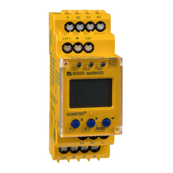
Insulation monitoring device for unearthed it ac-, ac/dc and dc systems for railway applications up to ac/dc 400 v
Hide thumbs
Also See for ISOMETER isoRW425:
- Manual (76 pages) ,
- Quick start manual (13 pages) ,
- Manual (72 pages)

Related Manuals for Bender ISOMETER isoRW425


Summary of Contents for Bender ISOMETER isoRW425
- Page 1 Manual ISOMETER® isoRW425 Insulation monitoring device for unearthed IT AC-, AC/DC and DC systems for railway applications up to AC/DC 400 V Software version: D418 V1.0x isoRW425_D00052_01_M_XXEN / 03.2014...
- Page 2 Bender GmbH & Co. KG Londorfer Str. 65 • 35305 Grünberg • Germany P.O. Box 1161 • 35301 Grünberg • Germany Tel.: +49 6401 807-0 Fax: +49 6401 807-259 E-Mail: info@bender.de Web: http://www.bender.de © Bender GmbH & Co. KG All rights reserved.
-
Page 3: Table Of Contents
Table of Contents 1. Making effective use of this document ............5 How to use this manual ................. 5 Information about factory setting ............. 5 2. Safety instructions ................... 7 General safety instructions ................7 Work activities on electrical installations ..........7 Intended use ...................... - Page 4 Table of Contents Connection ...................... 17 Commissioning ....................20 5. Operation and configuration ..............21 Factory setting ....................21 Getting to know the user interface ............22 Understand the display elements ............23 5.3.1 Querying measured values ................ 24 5.3.2 Alarm indication when an insulation fault has been detected ..26 Display in menu mode ................
-
Page 5: Making Effective Use Of This Document
1. Making effective use of this document 1.1 How to use this manual This manual is intended for electrically skilled persons working in electrical engineering and electronics! To make it easier for you to understand and revisit certain sections of text and instructions in the manual, we have used symbols to identify important in- structions and information. - Page 6 Making effective use of this document isoRW425_D00052_01_M_XXEN / 03.2014...
-
Page 7: Safety Instructions
2.1 General safety instructions In addition to these operating instructions, the "Important safety instructions for Bender products“, which are also included in the scope of supply, are an in- tegral part of the device documentation. 2.2 Work activities on electrical installations... - Page 8 Safety instructions DC components existing in AC/DC systems do not influence the operating characteristics. A separate supply voltage allows de-energised systems to be monitored too. The maximum permissible system leakage capacitance is 300μF. isoRW425_D00052_01_M_XXEN / 03.2014...
-
Page 9: Function
N/C operation or N/O operation selectable Automatic device self test BMS interface (Bender measuring device interface) for data exchange with other Bender components; RS-485 electrically isolated Start-up delay, response delay and delay on release ... - Page 10 Function A fault at conductor L+ or L– or a symmetrical insulation fault is shown on the display. In case of asymmetrical DC faults, a + or a - sign will be displayed in addition to the value. Pressing the arrow up and down button allows scrolling up and down in the display via the division of the insulation resistance up to the percentage value.
-
Page 11: Undervoltage/Overvoltage Monitoring
Function 3.2.1 Undervoltage/overvoltage monitoring In the response value menu AL both parameters can be activated resp. deac- tivated. The maximum undervoltage value is limited by the overvoltage value. 3.2.2 Connection monitoring After connecting to the supply voltage, the following connections are checked periodically, every 24 h (can be adjusted) or by pressing the test but- ton T: –... -
Page 12: Malfunction
Function While the internal test button T is pressed and held, all display elements avail- able for this device are shown. During the test, the display indicates "tES". 3.2.5 Malfunction In the event of an internal malfunction, all three LEDs will flash. An error code will appear on the display, refer to page 53. -
Page 13: Password Protection (On, Off)
Function 3.2.8 Password protection (on, OFF) If password protection has been activated (on), settings can only be made subject to the correct password being entered (0…999). 3.2.9 Automatic adaptation of the pulse duration After connection to the supply voltage, the device automatically adjusts itself to the leakage capacitance and the insulation resistance of the system to be monitored. - Page 14 Function ated measured values from the fault memory are imported to the history memory. This data can be read out using the HiS menu item. In order to be able to record a new data record for a subsequent fault, the history memory must first be cleared via the menu using the Clr button.
-
Page 15: Installation, Connection And Commissioning
4. Installation, connection and commissioning Risk of electric shock! Touching uninsulated live conductors can result in death or seri- ous injury. Therefore avoid any physical contact with active con- ductors and ensure compliance with the regulations for working on electrical installations. isoRW425 complies with the EMC limits for Class A devices in- tended for use in industrial environments. - Page 16 Installation, connection and commissioning Dimension diagram, sketch for screw mounting, push-wire terminal con- nection: 36 mm The front plate cover can be opened at the lower part marked with an arrow. isoRW425_D00052_01_M_XXEN / 03.2014...
-
Page 17: Connection
Installation, connection and commissioning 4.2 Connection Connect the terminals A1 and A2 to the supply voltage according to IEC 60364-4-43, i.e. the connections are to be protected against short-circuit by means of a protective device (a 6 A fuse is recommended). Devices for protection against short-circuit in conformity with IEC 0100-430 for the coupling of terminals L1/L2 to the IT system to be monitored can be omitted if the wiring is carried out in such a manner as to reduce the risk of a... - Page 18 Installation, connection and commissioning Connect the device as illustrated in the wiring diagram: L1/+ COM460IP Test / Reset isoRW425 RS-485 isoRW425_D00052_01_M_XXEN / 03.2014...
- Page 19 Installation, connection and commissioning For details about the conductor cross sections necessary for the wiring refer to page 51. Terminal Connections Connection to the supply voltage via fuse (line protection). A1, A2 If being supplied from an IT system, both lines have to be pro- tected by a fuse.
-
Page 20: Commissioning
Installation, connection and commissioning 4.3 Commissioning 1. Check that the ISOMETER® is properly connected to the system to be monitored. 2. Connect the supply voltage to the ISOMETER®. The device carries out a calibration, a self test and adjusts itself to the IT system to be monitored. -
Page 21: Operation And Configuration
5. Operation and configuration Factory setting The most important settings are listed in the summary below. A complete list is presented in section 5.4.2 starting on page 29. Response value R (prewarning): 40 kΩ Response value R (alarm): 10 kΩ Response value Z (Alarm): deactivated... -
Page 22: Getting To Know The User Interface
Operation and configuration 5.2 Getting to know the user interface User interface Element Function Lights continuously: Power On LED; green flashes: system fault or malfunction of connection monitoring LED Alarm 1 lights continuously: Response value 1 reached, manual self test LED Alarm 1 flashes: Yellow Overvoltage or system fault;... -
Page 23: Understand The Display Elements
Operation and configuration 5.3 Understand the display elements L1L2 > µ kM % < test onoff MAdr 1. Display field of measurement modes: U = mains voltage, R = insulation resistance, Z = insulation impedance, C = leakage capacitance 2. Display field of the conductors being monitored 3. -
Page 24: Querying Measured Values
Operation and configuration 5.3.1 Querying measured values The standard display shows the currently measured insulation resistance in its default setting. The measured values below can be queried by scrolling with the UP or DOWN button. If a value other than the insulation resistance is to be permanently displayed, the selection is to be confirmed with Enter. - Page 25 Operation and configuration Measured Explanation/ Measured variable value display additional information 8. Switch display 9. System voltage L1/+ against PE Display of the DC value V 10. Switch display 11. System voltage L2/– against PE; Display of the DC value V 12.
-
Page 26: Alarm Indication When An Insulation Fault Has Been Detected
Operation and configuration 5.3.2 Alarm indication when an insulation fault has been detect- When the value falls below the response value R the LED AL1 signals a prewarning. AL1 AL2 When the value of the insulation resistance meas- ured falls below the response value R too, the LED AL2 signals an alarm. -
Page 27: Display In Menu Mode
– Activate or deactivate password protection, change password – Switch the connection monitoring on or off – Restore factory setting – Service menu SyS (for Bender Service only) Querying software version Querying and clearing the history memory, also refer to page 13 Go to the next highest menu level (back) isoRW425_D00052_01_M_XXEN / 03.2014... -
Page 28: Navigation Within The Menu
Operation and configuration 5.4.2 Navigation within the menu The menu structure is illustrated briefly on the following pages. After pressing the "MENU" button for approx. 2 seconds the first menu item AL appears. The Up and Down buttons and the Enter button can be used for navigating between the menus and to carry out settings. - Page 29 Operation and configuration Factory setting Menu Activati Menu Value Configurable parameter to call Menu Response value R < R1 – 40 kΩ (prewarning AL1) Response value R < R2 – 10 kΩ (Alarm AL2) – Response value Z < Z 10 kΩ...
- Page 30 Repetition time self test Password protection deactiva. System frequency for imped- – 50 Hz ance calculation – Connection monitorin. system Restore factory settings For Bender-Service only – – – – Display software version Display fault memory for the – –...
-
Page 31: Selecting Menus
Operation and configuration 5.4.3 Selecting menus Press and hold down the MENU button for more than 1.5 seconds to call up the menu. Menus are available for a variety of settings. The out menu provides an additional menu level for each of the K1/K2 relays. Description/Configurable parameters Menu/Button to call Query and set response values:... - Page 32 Switch the monitoring function of the system connection on or off Restore factory settings Service menu SyS for Bender Service only 4. Press the UP/DOWN buttons to go to the menu. Querying software version 5.
-
Page 33: Making Settings In The Al Menu
Operation and configuration 5.4.4 Making settings in the AL menu When carrying out settings, take into account that: R is always smaller than , the response value for undervoltage is always smaller than the response value for overvoltage. 1. Select menu item AL. 2. - Page 34 Operation and configuration Activate/deactivate pa- Change parameter Change/apply par- AL menu Select sub menu rameters value display 6. Switch sub menu 7. Set response value for under- voltage 8. Switch sub menu 9. Set response value for over- voltage 10. Switch sub menu 11.
-
Page 35: Making Settings In The Out Menu
Operation and configuration 5.4.5 Making settings in the out menu 1. Select the out menu. 2. Change the parameters as illustrated. To go back to the menu level after parameter change, press and hold down the MENU button for more than 1.5 seconds once you have modified the pa- rameter(s). - Page 36 Operation and configuration Menu item Change/activate/deacti- Change parameter Change/apply par- Select sub menu vate/change param value display 4. Set the alarm relay K1 to N/O operation (n.o.) 5. Set the alarm relay K1 to N/C operation (n.c.) 6. Switch sub menu 7.
- Page 37 Operation and configuration Menu item Change/activate/deacti- Change parameter Change/apply par- Select sub menu vate/change param value display 8. Set alarm relay K2 to N/C oper- ation (n.c.) 9. Switch sub menu 10. Set BMS address 11. Switch sub menu 12. Assign category device error to alarm relay K1 13.
- Page 38 Operation and configuration Menu item Change/activate/deacti- Change parameter Change/apply par- Select sub menu vate/change param value display 16. Assign pre- warning insula- tion fault R at L2/– to alarm relay K1 17. Switch category 18. Assign alarm insulation fault R at L1/+ to alarm relay K1 19.
- Page 39 Operation and configuration Menu item Change/activate/deacti- Change parameter Change/apply par- Select sub menu vate/change param value display 24. Assign under- voltage fault to alarm relay K1 25. Switch category 26. Assign overvolt- age fault to alarm relay K1 27. Switch category 28.
- Page 40 Operation and configuration Menu item Change/activate/deacti- Change parameter Change/apply par- Select sub menu vate/change param value display 34. Switch back to the out menu No alarm activated due to deactivated alarm relay Deactivating an alarm relay (K1/K2) via the menu prevents alarm signalling by the respective NO contact! An alarm will be sig- nalled by the respective alarm LED (AL1/AL2) only! Check the settings in the out menu!
-
Page 41: Making Settings In The Menu Item T
Operation and configuration 5.4.6 Making settings in the menu item t 1. Select menu t. 2. Change the parameters as illustrated. 3. To go back to the menu level after parameter change, press and hold down the MENU button for more than 1.5 seconds. Activate/deactivate pa- Change parameter Change/apply par-... - Page 42 Operation and configuration Activate/deactivate pa- Change parameter Change/apply par- Menu t Select sub menu rameters value display 8. Switch sub menu 9. Switch back to menu t isoRW425_D00052_01_M_XXEN / 03.2014...
-
Page 43: Making Settings In The Set Menu
Operation and configuration 5.4.7 Making settings in the SEt menu 1. Select the SEt menu. 2. Change the parameters as illustrated. 3. To go back to the menu level after parameter change, press and hold down the MENU button for more than 1.5 seconds. Change/activate/deacti- Change parameter Change/apply par-... - Page 44 Operation and configuration Change/activate/deacti- Change parameter Change/apply par- SEt menu Select sub menu vate/change param value display 3. Deactivate password pro- tection 4. Switch sub menu 5. Select system frequency for impedance measurement 6. Switch sub menu 7. Switch on mon- itoring for sys- tem connection isoRW425_D00052_01_M_XXEN / 03.2014...
- Page 45 Operation and configuration Change/activate/deacti- Change parameter Change/apply par- SEt menu Select sub menu vate/change param value display 8. Switch off the monitoring function for sys- tem connection 9. Switch sub menu 10. Restore factory setting "run" appears on the display and the device is reset to the factory settings automatically 11.
- Page 46 Operation and configuration Change/activate/deacti- Change parameter Change/apply par- SEt menu Select sub menu vate/change param value display 13. Switch sub menu 14. Go back to SEt menu isoRW425_D00052_01_M_XXEN / 03.2014...
-
Page 47: Querying Software Number And Software Version With The Inf
Operation and configuration 5.4.8 Querying software number and software version with the INF menu 1. Select the INF menu. The software number and software version is displayed as a running text. Once all information is shown on the display, you can use the UP/DOWN but- tons to select individual data sections. - Page 48 Operation and configuration Explanation/ HiS menu Error display/Sub menu additional information 6. Switch error display 7. Query system voltage L1/+ Example: L1L2 against L2/– Display of the r.m.s. value V < the AC system 8. Switch error display 9. Query system voltage L1/+ against PE Display of the DC value V 10.
-
Page 49: Technical Data
6. Technical data 6.1 Tabular presentation ( )* = factory setting Insulation coordination acc. to IEC 60664-1/IEC 60664-3 Rated voltage (A1, A2) - (11, 14, 24) ........................300 V Rated voltage (L1/+, L2/-, E, KE, T/R, A, B)......................400 V Rated impulse withstand voltage .......................... - Page 50 Technical data Response value Z ..........................1…990 kΩ (off)* Operating uncertainty....................... ± 15 %, at least ±1 kΩ Hysteresis ............................25 %, at least 1 kΩ Undervoltage detection ........................10…499 V (off)* Overvoltage detection........................11…500 V (off)* Operating uncertainty........................± 5 %, at least ± 5 V Hysteresis ..............................
- Page 51 Technical data Contact 11-24 ..............................Alarm 2 Electrical endurance, number of cycles ....................... 10000 Contact data acc. to IEC 60947-5-1: Utilisation category.............. AC-12..AC-14 ..DC-12 ..DC-12 ..DC-12 Rated operational voltage .............230 V...230 V.....24 V..110 V..220 V Rated operational current ............5 A....2 A ....1 A ... 0.2 A ..0.1 A Minimum contact rating ......................
-
Page 52: Standards, Approvals And Certifications
Technical data flexible with ferrules ....................0.2…1.5 mm2 (AWG 24…16) Stripping length ..............................10 mm Opening force................................50 N Test opening, diameter............................2.1 mm Other Operating mode ..........................continuous operation Mounting...................... cooling slots must be ventilated vertically Degree of protection, built-in components (DIN EN 60529) ................. IP30 Degree of protection, terminals (DIN EN 60529) .................... -
Page 53: Error Codes
If necessary, eliminate connection error, otherwise per- E.xx form reset. Restore the device to the factory setting. The error code will be erased automatically once the error has been eliminated. Should the error persist, contact Bender Service. isoRW425_D00052_01_M_XXEN / 03.2014... - Page 54 Technical data isoRW425_D00052_01_M_XXEN / 03.2014...
-
Page 55: Index
INDEX Activate or deactivate the fault memory 35 Factory setting 13 Activate or diactivate password 27 Fault memory 13 Adaptation of the measuring pulse length Getting to know the user interface 22 Adjustable parameters, list 29 AL menu 33 Alarm indication when an insulation fault HiS menu 47 has been detected 26 History memory 13... - Page 56 INDEX - out (fault memory, alarm relay) 29 - Set (device control) 30 Safety instructions 7 - t (timing check) 30 Selecting menus 31 Menu item out 35 Self test, automatic 11 Menu structure 28 Self test, manual 11 Set BMS address 27 Navigation within the menu 28 SEt menu 43 Setting time delays 41...
- Page 57 INDEX isoRW425_D00052_01_M_XXEN / 03.2014...
- Page 58 INDEX isoRW425_D00052_01_M_XXEN / 03.2014...
- Page 60 D0005201MXXEN Bender GmbH & Co. KG Londorfer Str. 65 • 35305 Grünberg • Germany Postfach 1161 • 35301 Grünberg • Germany Tel.: +49 6401 807-0 Fax: +49 6401 807-259 E-Mail: info@bender.de Web: http://www.bender.de...
Need help?
Do you have a question about the ISOMETER isoRW425 and is the answer not in the manual?
Questions and answers