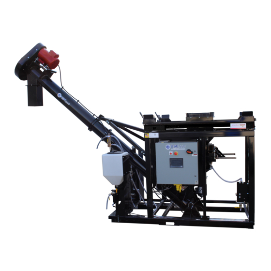
USC AT500H Operator's Manual
Automated treater w/loss in weight seed metering
Hide thumbs
Also See for AT500H:
- Operator's manual (42 pages) ,
- Quick start manual (8 pages) ,
- Troubleshooting (4 pages)
Table of Contents

Related Manuals for USC AT500H


Summary of Contents for USC AT500H
- Page 1 AT500H AUTOMATED TREATER W/LOSS IN WEIGHT SEED METERING Operators Manual Software Release: AT500 v2.1 TD-09-06-1078 Revision: B 2023 Document: Effective Date: JAN 2320 124th Road, Sabetha, Kansas 66534 www.uscllc.com Phone (785) 431-7900...
- Page 2 OVERVIEW The purpose of this manual is to provide you with the basic information needed to operate and maintain the AT500H Automated Treater. It does not hold USC, LLC liable for any accidents or injuries that may occur. The technical information provided in this document is based on extensive testing under controlled conditions at the USC research and development facility.
-
Page 3: Table Of Contents
Main Control Panel Connections ..........16 Section C Mechanical Operation ............18 AT500H Automated Treater Overview ........18 Loss In Weight Slide Gate and Atomizer Overview ....19 Peristaltic Pump Head and Motor ........... 20 Seed Treatment Valves ............21 Flow Meters ................ -
Page 4: Section A
AT500H TREATER Safety Instructions Section Every year accidents in the work place maim, kill and injure people. Although it may be impossible to prevent all accidents, with the right combination of training, operating practices, safety devices and operator vigilance, the number of accidents can be significantly reduced. - Page 5 AT500H TREATER Mandatory Lockout Power Symbol. Disconnect, lockout and tagout electrical and other energy sources before inspecting, cleaning or performing maintenance on this panel. International Safety Alert Symbol. The exclamation point (!) surrounded by a yellow triangle indicates that an injury hazard exists.
- Page 6 AT500H TREATER LOCKOUT / TAGOUT PROCEDURES Lockout/Tagout is the placement of a lock/tag on an energy isolating device in accordance with an established procedure. When taking equipment out of service to perform maintenance or repair work, always follow the lockout/tagout procedures as outlined in OSHA Standard 1910.147.
- Page 7 PPE is being used: 29 CFR § 1910.333 and 29 CFR § 1910.137. No responsibility is assumed by USC, LLC for any consequences arising out of the use of this material.
- Page 8 AT500H TREATER YOU are responsible for the SAFE operation and maintenance of your USC, LLC equipment . YOU must ensure that you and anyone else who is going to operate, maintain or work around the equipment be familiar with the operating and maintenance procedures and related SAFETY information contained in this manual.
- Page 9 AT500H TREATER 4. Provide a fire extinguisher for use in case of an accident. Store in a highly visible place. 5. Do not allow children, spectators or bystanders within hazard area of machine. 6. Wear appropriate protective gear. This includes but is not limited A hard hat •...
- Page 10 AT500H TREATER PLACEMENT SAFETY 1. Move only with the appropriate equipment 2. Stay away from overhead power lines when moving equipment. Electrocution can occur without direct contact. 3. Be familiar with machine hazard area. If anyone enters hazard areas, shut down machine immediately.
-
Page 11: Safety Labels
Small air pockets can be pierced with a pin and smoothed out using the piece • of sign backing paper. Located on the USC equipment you will find safety labels. Always be sure to read and follow all directions on the labels. Guards provided with USC equipment are to remain in place during operation. - Page 12 AT500H TREATER Think SAFETY! Work SAFELY! REMEMBER—If safety labels have been damaged, removed, become illegible, or parts replaced without safety labels, new labels must be applied. New safety labels are available from your authorized dealer. Part # 09-02-0003 Part # 09-02-0002...
- Page 13 AT500H TREATER Part # 09-02-0001 Part # 09-02-0010 Part # 09-02-0012 Page 13...
-
Page 14: Section B
2. Be sure there is enough clearance from overhead obstructions and power lines or other equipment to move the machine into its working position. 3. Using a forklift, place the AT500H Treater in the desired position on a level surface. USC highly recommends that the AT500H Treater be set up inside... - Page 15 Provide convenient shut- down switches, comply with local electrical codes and ensure that the system is properly grounded and bonded. All USC control panels must be connected adhering to the same electrical re- quirements as specified in the main control panel...
-
Page 16: Main Control Panel Connections
AT500H TREATER MAIN CONTROL PANEL CONNECTIONS MAIN CONTROL PANEL CONNECTIONS 1. To use the U-Connect Mini remote support capabilities; connect an internet connected ethernet cable to the Customer Supplied Internet port. 2. There are three MODBUS TCP Ethernet connectors on the Control Panel. These are used to connect to pump # 3&4, wireless access point for tablet control, printer,... - Page 17 AT500H TREATER MAIN CONTROL PANEL CONNECTIONS 8. Connect the cable from the Pump #2 Motor to the Motor Pump #2 connector. The number two pump is the one farthest from the control panel. This is factory connected. 9. Auger motor power cord. This is factory connected.
-
Page 18: Section C
AT500H TREATER Mechanical Operation Section AT500H AUTOMATED TREATER OVERVIEW Auger Drive Belt Assembly Pro Box Auger Motor Platform Additive Automated Feeder Control Panel Treatment Valves Treatment Tank Pump Motor Atomizer Plumbing Chamber To Atomizer Atomizer Motor Page 18... -
Page 19: Loss In Weight Slide Gate And Atomizer Overview
AT500H TREATER LOSS IN WEIGHT SLIDE GATE AND ATOMIZER CHAMBER The atomizer chamber consists of a patented design which disperses treatment evenly to each seed. A motor drives the atomizer head at approximately 1725 RPM’s. As treatment is being pumped into the atomizer chamber, it drops into the atomizer head. -
Page 20: Peristaltic Pump Head And Motor
AT500H TREATER PERISTALTIC PUMP HEAD AND MOTOR The pump stand utilizes a variable speed pump motor and special norprene pump tubing for liquid metering. Each pump comes equipped with 1 peristaltic pump head. Liquid will only come into contact with the inside diameter of the pump tubing and not the pump. -
Page 21: Seed Treatment Valves
AT500H TREATER SEED TREATMENT VALVES SEED TREATMENT VALVES (Left Pump Stand): When the handle of the bottom valve is in the horizontal position the liquid recirculates back into the top of the tank. In the vertical position it sends the liquid up to the top valve. -
Page 22: Flow Meters
AT500H TREATER FLOW METERS The pump stands are equipped with volumetric flow meters. A flow meter is used to perform real - time chemical flow adjustments and monitoring without the operator having to handle the chemical. The flow meter reading will be displayed on the HMI touch screen and can be set to read in oz / min or ml / min. -
Page 23: Section D
Never allow anyone who has not read and familiarized themselves with the owner’s manual to open or work on the control panels. USC recommends the use of a surge protection device with NOTICE a minimum rating of 400 Joules for all automated main control panels. -
Page 24: Main Screen
AT500H TREATER MAIN SCREEN This screen informs the operator of the status of all system motors and electrical devices and allows for control / adjustment of system operations. 1. DATE & TIME: The date and time are displayed in the upper left corner of the screen. - Page 25 AT500H TREATER MAIN SCREEN DESCRIPTIONS 2. TREATER STATUS DISPLAY: Displays the current treater status. Here the operator will be able to identify if the treater is in an Emergency Stop state, in an Alarm state, Recipe Not Satisfied, or Idle.
- Page 26 AT500H TREATER MAIN SCREEN DESCRIPTIONS 9. HARDWARE STATUS DISPLAY: Displays current status of all configured hardware. Listed are devices such as the Scale Weight, Inlet Conveyor (if used), High Level Proximity Sensor, Seed Present Proximity Sensor, Seed Metering, Atomizer, Auger, Auxiliary Controls, Pump Controls.
- Page 27 AT500H TREATER MAIN SCREEN DESCRIPTIONS 11. RUN SETUP (Continued): Pressing the Device Settings will allow the Device Settings to be viewed and edited. Here, Start Delays and Stop Delays can be adjusted to meet the needs of the automated run.
-
Page 28: H-O-A Screen
AT500H TREATER Treater H-O-A (HAND-OFF-AUTO) SCREEN These H-O-A buttons force the selected component to be energized (HAND), de-energized (OFF), or automatically energized by the normal logic sequence (AUTO). The HAND function will cause the component to operate independent of whatever else the system is trying to do automatically. These functions should not normally be used if the automated sequencing is active. - Page 29 AT500H TREATER Ingredient H-O-A (HAND-OFF-AUTO) SCREEN Page 29...
- Page 30 AT500H TREATER H-O-A (HAND-OFF-AUTO) SCREEN 1. DEVICE NAME DISPLAY: Displays the device name. 2. REVERSE BUTTON: Pressing this button will put the corresponding device in the Reverse state. In the Reverse state the motor will energize and run opposite of the standard direction.
- Page 31 AT500H TREATER H-O-A (HAND-OFF-AUTO) SCREEN 13. PUMP CALIBRATION BUTTON: Pressing this button will present the Pump Cali- bration popup. Here a pump can be calibrated to the Ingredient that is assigned to it. Pressing the Pump 1 button or Pump 2 button will select that pump for calibration.
-
Page 32: Profile Editing Screens
AT500H TREATER PROFILE EDIT SCREENS There are commonalities between each of the profile editing screens. Editing screens include Reports, Customers, Ingredients, Seed Profiles, and Recipes. Each profile screen has a Navigation pane shown on the left. Pressing Find Name will bring up a keyboard allow the operator to search for a record. -
Page 33: Reports Screen
At the bottom half of the Reports page Ingredient Usage is detailed and whether the Auxiliary controls were used during the run. If a USC 8.5”x11” printer is connected to the system, the Print button can be pressed to print the currently selected report. -
Page 34: Customers
AT500H TREATER PROFILE EDITING SCREENS CUSTOMERS: Pressing Customers from the Navigation Bar will present the Customer screen. Select a Customer on the Profile Navigation Pane at the left to edit an existing customer. To create a new customer press the New button and edit the needed fields. -
Page 35: Ingredients
AT500H TREATER PROFILE EDITING SCREENS INGREDIENTS: Pressing Ingredients from the Navigation Bar will present the Ingredients screen. Select an ingredient on the Profile Navigation Pane at the left to edit an existing ingredient. To create a new ingredient press the New button and edit the needed fields. -
Page 36: Seed Profiles
AT500H TREATER PROFILE EDITING SCREENS SEED PROFILES: Pressing Seed Profiles from the Navigation Bar will present the Seed Profiles screen. Select a seed profile on the Profile Navigation Pane at the left to edit an existing seed profile. To create a new seed profile press the New button and edit the needed fields. -
Page 37: Recipes
AT500H TREATER PROFILE EDITING SCREENS RECIPES: Pressing Recipes from the Navigation Bar will present the Recipes screen. Select a recipe on the Profile Navigation Pane at the left to edit an existing ingredient. To create a new recipe press the New button and edit the needed fields. Press the Save button to save changes. -
Page 38: Events Screen
AT500H TREATER EVENTS SCREEN The Events screen shows a listing of system alarms and messages both current and reset. It also allows you to silence an active alarm and clear non active entries. To view the Alarms, the operator can press the Alarms in the top left of the screen. To view the Messages, the operator can press the Messages in the top left of the screen. -
Page 39: Section E
AT500H. Use the steps below for proper load cell calibration. 1. Ensure the machine is placed on level ground, scale transport levers (x4) are in the “down” position, and that the 4 feet from the scale are resting on the AT500H frame in a non-binding fashion. - Page 40 AT500H TREATER LOAD CELL CALIBRATION (CONTINUED) 7. Press and hold the calibration switch through the opening from the removal of the screw in the prior step for approximately 2 seconds until the display changes to SEtUP. This is best done with a small tool.(e.g. a 3/32 or 2mm Hex Key Wrench or small screwdriver.)
-
Page 41: Seed Flow Calibration
AT500H TREATER SEED FLOW CALIBRATION 1. Press the Run Setup button from the Main screen. Enter in the Target Treating Rate in pounds per minute. 2. Press the Seed Profile Screens button. Select the seed profile you wish to calibrate. The seed profile may be edited and the seed actuator gate may be calibrated for that seed. - Page 42 AT500H TREATER SEED FLOW CALIBRATION 3. (Continued): Return to the Seed Profile screen. Press the Min Gate Position button and use the keypad to enter the position discovered. Press Save to save the updates. Page 42...
-
Page 43: Flow Meter Calibration
AT500H TREATER FLOW METER CALIBRATION Due to the composition of some types of chemicals, additional flow meter calibration may be required. It is recommended that, like other calibration devices, the flow meter is checked regularly and calibrated when needed. When calibrating the flow meter, each chemical must be checked and adjusted for. - Page 44 4. From the Treater HOA screen, press the Pump Calibration button. Press the number of the pump you wish to calibrate and a calibration run time for the calibration. The longer the run time the more accurate the calibration. USC recommends a minimum of 60 seconds. Place a measuring receptacle under the calibration fitting discharge tube on the top valve.
-
Page 45: Treating Seed
AT500H TREATER TREATING SEED 1. From the HOA screen, press the Auto All Devices button to place the Actuator, Atomizer, and the Auger in Auto. The pumps and auxiliary devices will set themselves to Auto based on the currently selected recipe when leaving the HOA screen. - Page 46 AT500H TREATER TREATING SEED 3. (Continued): The pump will turn on the same way. Waiting for the pump start delay time defined in the Device Settings. The pump may be set to turn on a second or two before seed is flowing to ensure thorough coating of the first seed out of the box. The operator may open the seed gate first so after pressing the start button, the treating processing will begin immediately after the system is up and running.
- Page 47 AT500H TREATER TREATING SEED Pause Button Shutdown Button Page 47...
-
Page 48: Section F
AT500H TREATER Troubleshooting Section TROUBLESHOOTING Below is a table describing the most frequent problems and solutions with the USC AT500H Treater . For further assistance, contact your authorized dealer. Problem Possible Cause Solution Seed Gate Actuator will not 1. Loss in weight seed gate 1. - Page 49 AT500H TREATER Problem Possible Cause Solution Flow Meter is fluctuating 1. Pump is sucking air. Check and tighten all hose connections. 2. Restriction in the line. 1. Check filter to see if gasket is 3. Flow meter is not full of liquid missing or cracked.
- Page 50 AT500H TREATER Problem Possible Cause Solution Pump will not turn off in AUTO 1. Proximity switch is dirty. 1. Clean proximity switch when seed runs out. 2. Proximity switch is set too 2. Adjust the pump proximity sensitive. switch sensitivity by turning adjustment screw counter- clockwise.
-
Page 51: Proximity Sensor Adjustment Guide
AT500H TREATER PROXIMITY SWITCH ADJUSTMENT GUIDE If a proximity switch is not working properly, this can be caused by wear, dust, or even moisture. The first step is to clean the lens of the proximity switch. If this does not solve the problem, the next step would be to adjust the sensitivity of the proximity switch. -
Page 52: Section G
Section Maintenance Proper maintenance of the AT500H Treater is critical for peak performance, reliability and accuracy of this system. The following is a guideline for the type of maintenance and servicing that should be performed on this unit. Your environment and uses may require additional maintenance and service beyond this list to assure a reliable and safe unit. -
Page 53: Atomizer
AT500H TREATER ATOMIZER To access the inside of the atomizer housing, disconnect the motor power cable from the atomizer motor, push up on the quick release handle and slide out the atomizer. After completing maintenance, slide the atomizer back into the operating position, pull down quick release handle to lock it in place and reconnect the motor power cord. -
Page 54: Belt Tensioning And Alignment
AT500H TREATER DRIVE BELT TENSION & ALIGNMENT Power to the auger belt is transmitted through a V-belt. The V-belt drive system must be maintained at the proper belt tension and pulley alignment to obtain the desired performance and life. When maintaining the belt drive system for the electric drive... -
Page 55: Belt Tensioning Specification
AT500H TREATER V-Belt tensioning adjustment can be made using a tension meter or other type spring scale using the following procedure. After seating the belts in the groove and adjusting center distance so as to take up the slack in the belts, further increase the tension until only a slight bow on the slack side is apparent while the drive is operating under load. -
Page 56: Pumps-Plumbing-Flow Meter
AT500H TREATER PUMPS - PLUMBING - FLOW METER 1. Check pump in forward and reverse. 2. Make sure pump heads open and close smoothly. 3. Inspect tubing for uneven wear. Replace pump tubing often to ensure high flow rates can be achieved. - Page 57 AT500H TREATER Only use the vinegar and water solution mixed in these proportions to clean the flow meter. Use of any other cleaners, NOTICE especially cleaners containing harsh chemicals may perma- nently damage the sensors and seals inside the flow meter.
-
Page 58: Section H
Section Storage When storing the AT500H Seed Treater for long periods of time, the following procedure must be followed to reduce the chance of rust, corrosion and fatigue of the treater. You can also use these steps when storing the machine for the winter. - Page 59 AT500H TREATER Proper Storage of the treater for long periods of time is critical to reduce the chance of rust, corrosion and fatigue of the equipment. This is especially true when storing the treater in below freezing temperatures. The following is a guideline for the type of cleaning and maintenance that should be performed on this unit prior to storage.
- Page 60 AT500H TREATER NOTES: Page 60...
-
Page 61: Section I
4.Other Statements: Manufacturer’s employees or representatives’ oral or other written statements do not constitute warranties, shall not be relied upon by Buyer, and are not a part of the contract for sale or this limited warranty. The USC Warranty Manager is the final decision point for all warranty claims. - Page 62 AT500H TREATER DOCUMENT REVIEW RECORD DATE 10-2022 1-2023 USC, LLC 2320 124th Road Sabetha, KS 66534 Phone (785) 431-7900 EMAIL: sales-team@uscllc.com WEB: www.uscllc.com Page 62...
Need help?
Do you have a question about the AT500H and is the answer not in the manual?
Questions and answers