Table of Contents
Advertisement
Quick Links
Download this manual
See also:
Installation Manual
Advertisement
Table of Contents
Troubleshooting

Related Manuals for Emerson Daniel 3814


Summary of Contents for Emerson Daniel 3814
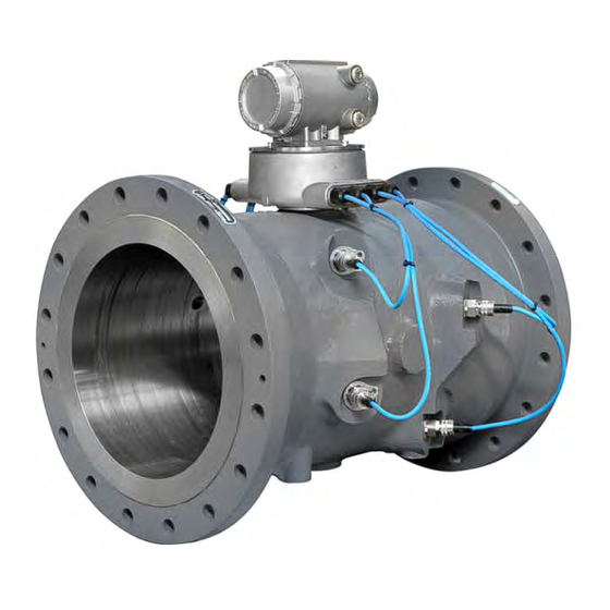
- Page 1 Maintenance and Troubleshooting Manual P a r t N u m b e r 3 - 9 0 0 0 - 7 6 4 R e v i s i o n F D e c e m b e r 2 0 1 7 Daniel 3814 Liquid Ultrasonic Flow Meter...
- Page 3 +44 (0)1786.433400 +44 (0)1786.433401 Middle East Africa (Dubai, UAE) +971 4 8118100 +971 4 8865465 Daniel Measurement and Control, Inc. (Headquarters) 11100 Brittmoore Park Drive Houston, TX 77041 USA http://www.Emerson.com Email • Customer Service: Daniel.SystemSales@Emerson.com • Customer Support: Daniel.SystemSales@Emerson.com •...
- Page 4 S i g n a l w o r d s a n d s y m b o l s Pay special attention to the following signal words, safety alert symbols and statements: Safety alert symbol This is a safety alert symbol. It is used to alert you to potential physical injury hazards. Obey all safety messages that follow this symbol to avoid possible injury or death.
- Page 5 I m p o r t a n t s a f e t y i n s t r u c t i o n s Daniel Measurement and Control, Inc. (Daniel) designs, manufactures and tests products to function within specific conditions. Because these products are sophisticated technical instruments, it is important that the owner and operation personnel strictly adhere both to the information printed on the product and to all instructions provided in this manual prior to installation, operation, and maintenance.
- Page 6 Product Operation Personnel: • To prevent personal injury, personnel must follow all instructions of this manual prior to and during operation of the product. • Follow all warnings, cautions, and notices marked on, and supplied with, this product. • Verify that this is the correct instruction manual for your Daniel product. If this is not the correct documentation, contact Daniel at 1-713-827-6314.
- Page 7 PRODUCT NAMES USED HEREIN ARE FOR MANUFACTURER OR SUPPLIER IDENTIFICATION ONLY AND MAY BE TRADEMARKS/REGISTERED TRADEMARKS OF THESE COMPANIES. DANIEL AND THE DANIEL LOGO ARE REGISTERED TRADEMARKS OF DANIEL INDUSTRIES, INC. THE EMERSON LOGO IS A TRADEMARK AND SERVICE MARK OF EMERSON ELECTRIC CO.
- Page 8 W a r r a n t y a n d L i m i t a t i o n s 1. LIMITED WARRANTY: Subject to the limitations contained in Section 2 herein, Daniel Measurement & Control, Inc. ("Daniel") warrants that the licensed firmware embodied in the Goods will execute the programming instructions provided by Daniel, and that the Goods manufactured by Daniel will be free from defects in materials or workmanship under normal use and care and Services will be performed by trained personnel using proper equipment and instrumentation for the particular Service provided.
-
Page 9: Table Of Contents
Maintenance and Troubleshooting Manual Table of Contents 3-9000-764 Rev F December 2017 Contents Preface Section 1: Routine maintenance Meter maintenance ..................1 Field hydrostatic pressure testing procedures ........... 3 Routine Maintenance ..................4 1.3.1 Maintenance logs and reports ................4 1.3.2 Pipeline cleaning maintenance ................ - Page 10 Table of Contents Maintenance and Troubleshooting Manual December 2017 3-9000-764 Rev F Transducer housing removal and installation ........... 43 3.3.1 Manually modifying the Calibration Parameters ..........48 Transducer cable removal and installation ............52 Replace the meter electronics ................ 60 3.5.1 Replace CPU Module or optional I/O Module............61 3.5.2 Fuse Replacement ....................63...
- Page 11 Maintenance and Troubleshooting Manual List of Tables 3-9000-764 Rev F December 2017 List of Tables Table 2-1 Troubleshooting ......................12 Table 2-2 Maintenance ........................20 Table A-1 Conversion factors per units of measurement ..............75 List of Tables...
- Page 12 List of Tables Maintenance and Troubleshooting Manual December 2017 3-9000-764 Rev F List of Tables...
- Page 13 Maintenance and Troubleshooting Manual List of Figures 3-9000-764 Rev F December 2017 List of Figures Figure 1-2 Flange stabilizers ......................2 Figure 1-3 Maintenance log collection parameters ................ 4 Figure 1-4 Trend log collection ...................... 5 Figure 1-5 Archive log collection parameters................. 6 Figure 1-6 High Viscosity meter tube and Venturi piping requirements .........
- Page 14 List of Figures Maintenance and Troubleshooting Manual December 2017 3-9000-764 Rev F Figure 3-21 Transmitter electronics ....................60 Figure 3-22 CPU or I/O Module replacement.................. 61 Figure 3-23 Transmitter electronics enclosure security seals ............62 Figure 3-24 Fuse holder cap ......................63 Figure 3-25 Backplane board replacement ...................
-
Page 15: Section 1: Routine Maintenance
3-9000-764 Rev F December 2017 Section 1: Routine maintenance Meter maintenance This section includes discussion of the maintenance of Daniel 3814 Liquid Ultrasonic Flow Meters. For reference, you may download the Daniel MeterLink Quick Start Manual from: http://www2.emersonprocess.com/en-US/brands/daniel/Flow/ultrasonics/Pages/Ultrasonic.aspx SURFACE TEMPERATURE HAZARD The meter body and piping may be extremely hot or cold Wear appropriate personal protective equipment when coming in contact with the meter. -
Page 16: Figure 1-2 Flange Stabilizers
Section 1: Routine maintenance Maintenance and Troubleshooting Manual December 2017 3-9000-764 Rev F CRUSHING HAZARD Do not remove flange stabilizers Attempting to do so may allow the meter to roll, resulting in serious injury or equipment damage. Figure 1-2 Flange stabilizers A. -
Page 17: Field Hydrostatic Pressure Testing Procedures
3-9000-764 Rev F December 2017 Field hydrostatic pressure testing procedures The Daniel 3814 Liquid Ultrasonic Flow Meter can be hydro-tested without any special preparations. The transducers are not exposed to the process pressure and can remain installed in the meter. -
Page 18: Routine Maintenance
Section 1: Routine maintenance Maintenance and Troubleshooting Manual December 2017 3-9000-764 Rev F Routine Maintenance Routine maintenance operations requires adherence to all applicable regulations and laws and safety training for personnel to perform the maintenance operations. Review your organization’s best practices procedures before performing routine maintenance. 1.3.1 Maintenance logs and reports To monitor the performance health of the meter, and ensure it is operating within acceptable... -
Page 19: Figure 1-4 Trend Log Collection
Maintenance and Troubleshooting Manual Section 1: Routine maintenance 3-9000-764 Rev F December 2017 Trend maintenance log collection Merging the results of two or more Maintenance logs into a single file, allows you to build a historical database of the meter’s performance. Trending the logs indicates changes from the original installation of the meter over time. -
Page 20: Figure 1-5 Archive Log Collection Parameters
Section 1: Routine maintenance Maintenance and Troubleshooting Manual December 2017 3-9000-764 Rev F Archive log collection Archive logs may be collected and the options include: • Daily log - generated every 24 hours on the Contract Hour. • Hourly log - generated every hour at the top of the hour. •... -
Page 21: Pipeline Cleaning Maintenance
Maintenance and Troubleshooting Manual Section 1: Routine maintenance 3-9000-764 Rev F December 2017 1.3.2 Pipeline cleaning maintenance BURST HAZARD Before pipeline cleaning and maintenance (“pigging operations”), remove straightening vanes or flow conditioners. Failure to do so may cause excessive pressure in the meter system, resulting in serious injury/death or equipment damage. -
Page 22: High Viscosity Piping Requirements
Section 1: Routine maintenance Maintenance and Troubleshooting Manual December 2017 3-9000-764 Rev F 1.3.3 High Viscosity piping requirements The piping requirements for High Viscosity meter applications are shown in Figure 1-6. HIGH VISCOSITY FLOW MEASUREMENT METER RECALIBRATION In high viscosity meter applications, if the connection between the upstream meter flange (Figure 1-6, Item... -
Page 23: Section 2: Troubleshooting
Maintenance and Troubleshooting Manual Section 2: Troubleshooting 3-9000-764 Rev F December 2017 Section 2: Troubleshooting APPENDIX A:DANIEL METERLINK Meter status alarms Run Daniel MeterLink and open the Meter Monitor (Summary) view to perform a diagnostics health check. Figure 2-1 Meter Monitor status alarms If the meter is measuring flow and operating within the established parameters the Meter Status LED is green. -
Page 24: Check Status
Section 2: Troubleshooting Maintenance and Troubleshooting Manual December 2017 3-9000-764 Rev F 2.1.1 Check status Click the button if any of the LEDs are yellow or red to see more specific Check Status information causing the status alarm. Some alarms do not require an acknowledge and will clear automatically when the alarm condition goes away. -
Page 25: Chord A, Chord B, Chord C And Chord D Alarm
Daniel MeterLink and the connected meter. For troubleshooting communications with the 475 Field Communicator for the HART® Protocol, refer to Section 5 of the Emerson 475 Field Communicator User’s Manual, Rev D. This manual may be downloaded from the following location: http://www2.emersonprocess.com/en-US/brands/Field-Communicator/Pages/Support.aspx... -
Page 26: Troubleshooting The Meter
Section 2: Troubleshooting Maintenance and Troubleshooting Manual December 2017 3-9000-764 Rev F Troubleshooting the meter and the following sections show errors that may occur with the meter hardware, Table 2-1 firmware or connections and recommended actions to resolve the problem(s). Table 2-1 Troubleshooting Error Recommended action(s) - Page 27 Maintenance and Troubleshooting Manual Section 2: Troubleshooting 3-9000-764 Rev F December 2017 Table 2-1 Troubleshooting Error Recommended action(s) CPU Module LINK LED is on but I If you are connecting for the first time, can't communicate with the meter • Enable the DHCP switch on the CPU Module using Ethernet •...
- Page 28 Section 2: Troubleshooting Maintenance and Troubleshooting Manual December 2017 3-9000-764 Rev F Table 2-1 Troubleshooting Error Recommended action(s) Communication issues due to • Blocked network ports on the computer running Daniel MeterLink or on a company blocked network ports LAN can prevent connections to the meter or prevent certain features from working.
- Page 29 December 2017 Table 2-1 Troubleshooting Error Recommended action(s) • Cannot communicate with 475 Field Refer to the Emerson 475 Field Communication User’s Manual, Rev F. This manual may Communicator be downloaded from the following location: http://www2.emersonprocess.com/en-US/brands/Field-Communicator/Pages/ Documentation.aspx — Note: The 375 Field Communicator is no longer available for purchase since the release of the 475 Field Communicator.
- Page 30 Section 2: Troubleshooting Maintenance and Troubleshooting Manual December 2017 3-9000-764 Rev F Table 2-1 Troubleshooting Error Recommended action(s) Flow pressure is outside the alarm • Startup Issues: limits — Verify that there is voltage to the pressure sensor from either the meter's power supply board or from an external power supply.
- Page 31 Maintenance and Troubleshooting Manual Section 2: Troubleshooting 3-9000-764 Rev F December 2017 Table 2-1 Troubleshooting Error Recommended action(s) • Program download failed during If the meter power fails during a firmware upgrade process, perform a backup firmware upgrade upgrade in an attempt to connect to the meter and download the program again. —...
- Page 32 Section 2: Troubleshooting Maintenance and Troubleshooting Manual December 2017 3-9000-764 Rev F Table 2-1 Troubleshooting Error Recommended action(s) One or more of the chords is not • Check for loose connections at the cable connectors. indicating a reading (reporting Ω •...
-
Page 33: Meter Maintenance
Maintenance and Troubleshooting Manual Section 2: Troubleshooting 3-9000-764 Rev F December 2017 2.2.1 Meter maintenance The Monitor (Summary) includes the direction of flow measurement, velocity rate, units of measurement, uncorrected or corrected flow (if applicable for your meter) and a bar graph for a visual comparison between the velocities for each chord. - Page 34 Section 2: Troubleshooting Maintenance and Troubleshooting Manual December 2017 3-9000-764 Rev F The following details the information displayed in this dialog box. • Flow Properties Table - the table at the top of the Meter Monitor dialog box shows basic information about the condition of the flow in the meter.
- Page 35 Maintenance and Troubleshooting Manual Section 2: Troubleshooting 3-9000-764 Rev F December 2017 Table 2-2 Maintenance Daniel MeterLink utility Diagnostics Action(s) Meter Monitor (Detailed) view • • Flow Profile Flow profile ratios can be viewed by clicking on the arrows in the upper left of the chart.
- Page 36 Section 2: Troubleshooting Maintenance and Troubleshooting Manual December 2017 3-9000-764 Rev F Table 2-2 Maintenance Daniel MeterLink utility Diagnostics Action(s) • • Meter Monitor (Summary) view Flow velocity Check the flow direction. If reverse Meter Flow Properties Table flow is detected, check for valve leaks. •...
- Page 37 Maintenance and Troubleshooting Manual Section 2: Troubleshooting 3-9000-764 Rev F December 2017 Table 2-2 Maintenance Daniel MeterLink utility Diagnostics Action(s) Meter Monitor (Detailed) view • • Electronics Temperature out of Temperature of the electronics is out Meter Data List range of nominal operating range below -40 °C or above 100 °C (-40 °F or above 212 °F).
- Page 38 Section 2: Troubleshooting Maintenance and Troubleshooting Manual December 2017 3-9000-764 Rev F Table 2-2 Maintenance Daniel MeterLink utility Diagnostics Action(s) • • MeterLink Tools Menu Analog outputs Run Analog Outputs test and verify outputs are within 4mA -20mA range — 0% = 4mA —...
- Page 39 Maintenance and Troubleshooting Manual Section 2: Troubleshooting 3-9000-764 Rev F December 2017 Meter Hardware Diagnostics Action(s) Meter Electronics • • Acquisition Module communications error Check firmware revision and upgrade if necessary using Daniel MeterLink Tools>Pro- gram Download. • If the CPU Module LED 5 is not flashing green, check interconnect cable between acquisition Module and the CPU Module.
- Page 40 Section 2: Troubleshooting Maintenance and Troubleshooting Manual December 2017 3-9000-764 Rev F Meter Hardware Diagnostics Action(s) • • MeterLink Tools>Edit/ Meter performed a Cold Start The meter configuration has reset to default Compare Configura- values and the meter is not configured tion Menu correctly to measure flow.
- Page 41 Maintenance and Troubleshooting Manual Section 2: Troubleshooting 3-9000-764 Rev F December 2017 Meter Components Visual Inspection Action(s) Security seals • • Endcap seals Only authorized personnel may • remove security seals. Follow your Endcaps latches standard operating procedure to • Transmitter Electronics Enclosure report seals that have been tampered •...
-
Page 42: Unable To Connect Direct Serial Or External Serial Modem
Address and Baud rate are correct in the Meter Directory record. For additional information on wiring and configuring the meter for the various communication options refer to the Daniel 3814 Liquid Ultrasonic Flow Meter Installation Manual (P/N 3-9000- 760, Section 3.5). -
Page 43: Troubleshoot Maintenance Log Files And Trend Files
Maintenance and Troubleshooting Manual Section 2: Troubleshooting 3-9000-764 Rev F December 2017 Troubleshoot Maintenance log files and trend files 2.3.1 Files Do Not Appear in Workbook Maintenance Log files and Trend files that exist on the PC do not appear in the Microsoft® Excel®... -
Page 44: Maintenance Logs Or Trend Files Are Not Created
Section 2: Troubleshooting Maintenance and Troubleshooting Manual December 2017 3-9000-764 Rev F 2.3.3 Maintenance Logs or Trend files are not created When using Excel® XP or later, some of the worksheets in the Maintenance Logs or Trend files are not created. If the Inspection sheet of the Maintenance Log file or the Charts sheet of a Trend file is not generated, it is probably because Excel®... -
Page 45: Figure 2-7 Excel® Trusted Access Setting
Maintenance and Troubleshooting Manual Section 2: Troubleshooting 3-9000-764 Rev F December 2017 Click the radio button and click to apply your Trust access to Visual Basic Project OKAY selections. Figure 2-7 Excel® Trusted Access Setting To enable Excel® 2007 to work with Daniel MeterLink customize the Ribbon to include the Developer tab, Figure 2-8 Excel®... -
Page 46: Figure 2-9 Excel® 2007 Developer Tab - Macro Security
Section 2: Troubleshooting Maintenance and Troubleshooting Manual December 2017 3-9000-764 Rev F Select Macro Security to access the Trust Center. Figure 2-9 Excel® 2007 Developer tab - Macro Security Select Macro Settings from the left panel, then click the Enable all macros (not recommended;... -
Page 47: Windows® Xp With Security Update
Maintenance and Troubleshooting Manual Section 2: Troubleshooting 3-9000-764 Rev F December 2017 2.3.4 Windows® XP with Security Update The Security Update for Windows® XP (823980) has a problem that causes the Show only maintenance log and trend workbooks check box in Daniel MeterLink to be ineffective. http://www.microsoft.com/downloads/en/details.aspx?FamilyID=2354406c-c5b6-44ac- 9532-3de40f69c074 Additionally, it may take longer to validate a workbook when you attempt to add it to the... - Page 48 Section 2: Troubleshooting Maintenance and Troubleshooting Manual December 2017 3-9000-764 Rev F Windows® XP with Security Update...
-
Page 49: Section 3: Meter Maintenance
December 2017 Section 3: Meter maintenance Meter maintenance This section includes discussion of the maintenance of Daniel 3814 Liquid Ultrasonic Meters. SURFACE TEMPERATURE HAZARD The meter body and piping may be extremely hot or cold Wear appropriate personal protective equipment when coming in contact with the meter. -
Page 50: Figure 3-2 Flange Stabilizers
Reference, Installation and Operation Manual December 2017 3-9000-764 Rev F Prior to lifting the unit, refer to the Daniel 3814 Liquid Ultrasonic Flow Meter nameplate or outline dimensional (general arrangement) drawing for the assembled weight. CRUSHING HAZARD Do not remove flange stabilizers Attempting to do so may allow the meter to roll, resulting in serious injury or equipment damage. - Page 51 Maintenance and Troubleshooting Manual Section 3: Meter maintenance 3-9000-764 Rev F December 2017 FLUID CONTENTS MAY BE UNDER PRESSURE When the meter is under pressure, DO NOT attempt to remove or adjust the transducer housing. Attempting to do so may release pressurized fluid, resulting in serious injury or equipment damage. FLUID CONTENTS MAY BE HAZARDOUS The meter must be fully depressurized and drained before attempting to remove the transducer housing.
- Page 52 Section 3: Meter maintenance Reference, Installation and Operation Manual December 2017 3-9000-764 Rev F CRUSHING HAZARD During meter installation or removal, always place the unit on a stable platform or surface that supports its assembled weight. Failure to do so could allow the meter to roll, resulting in serious injury or equipment damage. Meter maintenance...
-
Page 53: Transducer Field Removal And Installation
Maintenance and Troubleshooting Manual Section 3: Meter maintenance 3-9000-764 Rev F December 2017 Transducer field removal and installation The liquid ultrasonic meter transducers are a spring-loaded assembly with the piezoelectric element at one end and the electrical connection at the other end. Daniel 3810 Series Ultrasonic Flow Meters are supplied with transducers which are extractable while the line is pressurized. -
Page 54: Figure 3-5 Transducer Assembly
Section 3: Meter maintenance Reference, Installation and Operation Manual December 2017 3-9000-764 Rev F Figure 3-5 Transducer assembly A. Transducer cable (P/N 1-360-01-600) (max. length 15 ft.) B. Coupling nut C. Transducer retainer D. Transducer E. Transducer housing locking ring F. -
Page 55: Transducer Removal And Installation
Maintenance and Troubleshooting Manual Section 3: Meter maintenance 3-9000-764 Rev F December 2017 3.2.1 Transducer removal and installation CUTTING HAZARD Sharp edges may be present on the meter. Wear appropriate personal protective equipment when working on the meter. Failure to do so may cause serious injury. -
Page 56: Figure 3-7 Transducer Security Seal Removal
Section 3: Meter maintenance Reference, Installation and Operation Manual December 2017 3-9000-764 Rev F Supplies needed: • Dow Corning 111 Silicone compound • Dow Corning 200 Silicon oil • Loctite® Nickel anti-seize compound Before removing and installing transducer(s), connect to the meter using Daniel MeterLink and collect and save a Maintenance Log and configuration files. -
Page 57: Figure 3-8 Transducer Installation
Maintenance and Troubleshooting Manual Section 3: Meter maintenance 3-9000-764 Rev F December 2017 For all other transducers, place three drops of Dow Corning 200 Silicon Oil (12,500 Centistokes) (P/N 1-360-01-650) on the face of the transducer to be installed. Place the new transducer into the transducer housing. Rotate the transducer so that the alignment notch on the back of the transducer fits over the indexing pin on the back of the transducer housing. -
Page 58: Transducer Housing Removal And Installation
Section 3: Meter maintenance Reference, Installation and Operation Manual December 2017 3-9000-764 Rev F Transducer housing removal and installation Daniel 3810 Series Ultrasonic Flow Meters utilize transducer housings that contain the transducer and act as the pressure barrier between the transducers and the fluid. Under normal maintenance such as transducer replacement, the transducer housings do not need to be removed. -
Page 59: Figure 3-10 Transducer Disassembly
Maintenance and Troubleshooting Manual Section 3: Meter maintenance 3-9000-764 Rev F December 2017 FLUID CONTENTS MAY BE HAZARDOUS The meter must be fully depressurized and drained before attempting to remove the transducer housing. If fluid begins to leak from the transducer housing, immediately reinstall it. Failure to do so may cause serious injury or equipment damage. - Page 60 Section 3: Meter maintenance Reference, Installation and Operation Manual December 2017 3-9000-764 Rev F Before removing the transducer housing(s), slowly vent all line pressure on the meter to atmosphere pressure and drain the meter of fluid. Remove the transducer(s) security seals. See Warnings on Pages 39 and 40 of this document.
- Page 61 Maintenance and Troubleshooting Manual Section 3: Meter maintenance 3-9000-764 Rev F December 2017 Screw the transducer housing into the meter body. Ensure the transducer housing threads are properly aligned (avoid cross-threading the housing) with the meter body, then use a wrench on the hex bolt of the housing and slowly screw in a clockwise direction.
-
Page 62: Figure 3-11 Transducer Installation
Section 3: Meter maintenance Reference, Installation and Operation Manual December 2017 3-9000-764 Rev F Slide the locking ring onto the transducer housing in an orientation so that the locking ring bolt can be installed through the slot of the locking ring and into the threaded hole in the meter body. -
Page 63: Manually Modifying The Calibration Parameters
Maintenance and Troubleshooting Manual Section 3: Meter maintenance 3-9000-764 Rev F December 2017 3.3.1 Manually modifying the Calibration Parameters Use the Tools|Transducer Swap-out utility in Daniel MeterLink to easily update parameters such as path lengths, delay times, and delta times for chord. This is necessary anytime transducers or housings have to be replaced for a chord or if the meter has performed a cold start. -
Page 64: Figure 3-13 Transducer Swap Out Wizard - Select Components Page
Section 3: Meter maintenance Reference, Installation and Operation Manual December 2017 3-9000-764 Rev F Chord select components page When transducer pairs are replaced or the meter has performed a cold start, the corresponding meter calibration parameters must be updated for accurate operation. Select the chord parameters which have changed (see Figure 3-13 example: Transducers and Housings are... -
Page 65: Figure 3-14 Transducer Swap Out Wizard - Select Components Page
Maintenance and Troubleshooting Manual Section 3: Meter maintenance 3-9000-764 Rev F December 2017 Update Chord parameters page Enter the chord values for the removed components, the components added and the new Delay time and Delta time on this page. After the values are entered, click the Write to Meter button to apply the changes. - Page 66 Section 3: Meter maintenance Reference, Installation and Operation Manual December 2017 3-9000-764 Rev F Chord “L” Dimension Calculation The chord “L” dimension is calculated from the meter housing length and the transducer housing lengths as shown in Equation 3-2. The lengths of t he transducer housings are etched on on the individual components.
-
Page 67: Transducer Cable Removal And Installation
Maintenance and Troubleshooting Manual Section 3: Meter maintenance 3-9000-764 Rev F December 2017 Transducer cable removal and installation Daniel 3810 Series Ultrasonic Flow Meters have blue transducer cables and a transducer cable nut that threads directly into the back of the transducer housing. The cables use plastic glands that come with the meter. -
Page 68: Figure 3-16 Transducer Security Seal Removal
Section 3: Meter maintenance Reference, Installation and Operation Manual December 2017 3-9000-764 Rev F CUTTING HAZARD Sharp edges may be present on the meter. Wear appropriate personal protective equipment when working on the meter. Failure to do so may cause serious injury. -
Page 69: Figure 3-17 Flow Meter Transducer Tie Wraps
Maintenance and Troubleshooting Manual Section 3: Meter maintenance 3-9000-764 Rev F December 2017 Cut the tie wraps for the transducer cable you are replacing Figure 3-17 Flow meter transducer tie wraps A. Base enclosure transducer cable glands B. Cable ties (two locations for large size meters) C. - Page 70 Section 3: Meter maintenance Reference, Installation and Operation Manual December 2017 3-9000-764 Rev F Carefully prop the Transmitter Electronics Enclosure to the side. Make sure the enclosure is stable and does not roll. CRUSHING HAZARD During meter installation or removal, always place the unit on a stable platform or surface that supports its assembled weight.
-
Page 71: Figure 3-18 Flow Meter Acquisition Module Wiring
Maintenance and Troubleshooting Manual Section 3: Meter maintenance 3-9000-764 Rev F December 2017 Figure 3-18 Flow meter Acquisition Module wiring The relative position of the contacts is shown on the Acquisition Module label adjacent to the terminal block. When terminating the connector wires, ensure that the contacts clamp on the bare wires and not on the wire insulation. - Page 72 Section 3: Meter maintenance Reference, Installation and Operation Manual December 2017 3-9000-764 Rev F Inspect the Transmitter Electronics Enclosure gasket for wear and replace it if necessary. If replacing the gasket, lubricate it with Dow Corning 111 (P/N 2-9-9960-135). Attach one desiccant pack to the underside of the Base Enclosure cover. Place the Transmitter Electronics Enclosure onto the Base Enclosure.
-
Page 73: Figure 3-19 Transmitter Electronics Enclosure Security Seals
Maintenance and Troubleshooting Manual Section 3: Meter maintenance 3-9000-764 Rev F December 2017 If required, install the security seal wire into and through one of the two holes in the end cap. Choose holes that minimize counterclockwise rotation of the end cap when the security wire is taut (maximum wire diameter.078 inch;... -
Page 74: Figure 3-20 Base Enclosure Security Seals
Section 3: Meter maintenance Reference, Installation and Operation Manual December 2017 3-9000-764 Rev F If required, attach the security wire seals on the Base Enclosure. Figure 3-20 Base Enclosure security seals A. Transmitter Electronics Enclosure B. Security wire seals C. Transmitter Electronics endcap security latch D. -
Page 75: Replace The Meter Electronics
Maintenance and Troubleshooting Manual Section 3: Meter maintenance 3-9000-764 Rev F December 2017 Replace the meter electronics The following procedure should be performed by a qualified service technician or trained personnel. Observe all warning labels on the meter before starting this procedure. The Daniel 3410 Series Gas Ultrasonic Flow Meter Transmitter Electronics Enclosure consists of the following: •... -
Page 76: Replace Cpu Module Or Optional I/O Module
Section 3: Meter maintenance Reference, Installation and Operation Manual December 2017 3-9000-764 Rev F 3.5.1 Replace CPU Module or optional I/O Module Remove power to the meter. Refer to Figure 3-6 for the tools required to complete this procedure. Disconnect security seals on the Transmitter Electronics Enclosure (see Figure 3-7), loosen the end cap security latches using a 3 mm Allen wrench... -
Page 77: Figure 3-23 Transmitter Electronics Enclosure Security Seals
Maintenance and Troubleshooting Manual Section 3: Meter maintenance 3-9000-764 Rev F December 2017 If you are not replacing other electronics, replace the end caps and security latches (requires a 3 mm Allen wrench). If required, install the security seal wire into and through one of the two holes in the end cap. -
Page 78: Fuse Replacement
Section 3: Meter maintenance Reference, Installation and Operation Manual December 2017 3-9000-764 Rev F 3.5.2 Fuse Replacement Remove power to the meter. Refer to Figure 3-6 for the tools required to complete this procedure. Disconnect the Transmitter Electronics Enclosure security seals (see Figure 3-19), loosen the end cap security latch (requires a 3 mm Allen wrench) on the terminal end of... -
Page 79: Replace Backplane, I.s. Barrier Or Power Supply Board
Maintenance and Troubleshooting Manual Section 3: Meter maintenance 3-9000-764 Rev F December 2017 This completes the fuse replacement procedure. 3.5.3 Replace Backplane, I.S. Barrier or Power Supply board The following sections detail removal of the Backplane board, the I.S. Barrier Board and the Power Supply Board. - Page 80 Section 3: Meter maintenance Reference, Installation and Operation Manual December 2017 3-9000-764 Rev F Remove the Power Supply (if it was not removed with the Backplane board) and I.S. Barrier boards from the enclosure. The I.S. Barrier Board has a notched tab that secures the board to the Guide Plate.
-
Page 81: Figure 3-26 I.s. Barrier Board Replacement
Maintenance and Troubleshooting Manual Section 3: Meter maintenance 3-9000-764 Rev F December 2017 I.S. Barrier Board replacement If replacing the I.S. Barrier board, remove power to the meter. Refer to Figure 3-6 for the tools required to complete this procedure. Disconnect the Transmitter Electronics Enclosure security seals, loosen the end cap security latches with a 3mm Allen wrench and remove both end caps (see Figure... -
Page 82: Figure 3-27 Transmitter Electronics Enclosure Security Seals
Section 3: Meter maintenance Reference, Installation and Operation Manual December 2017 3-9000-764 Rev F Reinstall the terminal blocks (3 mm Allen wrench required) on the CPU Module, Optional I/O Module, I.S. Barrier Board and the Power Supply. Recheck the connections, wiring and switch settings before replacing the end caps. If replacing other electronics, continue with the following procedures before replacing the end caps and sealing the enclosure. -
Page 83: Figure 3-28 Power Supply Board Replacement
Maintenance and Troubleshooting Manual Section 3: Meter maintenance 3-9000-764 Rev F December 2017 Power Supply Board replacement If replacing the Power Supply board remove power to the meter. Refer to Figure 3-6 for the tools required to complete this procedure. Disconnect the Transmitter Electronics Enclosure security seals, loosen the end cap security latches with a 3mm Allen wrench and remove both end caps (see Figure... - Page 84 Section 3: Meter maintenance Reference, Installation and Operation Manual December 2017 3-9000-764 Rev F Recheck the connections, wiring and switch settings before replacing the end caps. If replacing other electronics, continue with Section 3.5.4 before replacing the end caps and sealing the enclosure. If you are not replacing other electronics, replace the Transmitter Electronics Enclosure end caps, install the end cap security latches (3mm Allen wrench required).
-
Page 85: Acquisition Module Replacement
Maintenance and Troubleshooting Manual Section 3: Meter maintenance 3-9000-764 Rev F December 2017 3.5.4 Acquisition Module replacement Remove power to the meter. Refer to Figure 3-6 for the tools required to complete this procedure. If the installation has rigid conduit, use a medium size crescent wrench and loosen the hex nuts on the Transmitter Electronics Enclosure. -
Page 86: Figure 3-30 Transmitter Electronics Enclosure And Base Enclosure Security Seal Removal
Section 3: Meter maintenance Reference, Installation and Operation Manual December 2017 3-9000-764 Rev F If the meter is equipped with security seals, remove the seals from the bolts on the Base Enclosure. Figure 3-30 Transmitter Electronics Enclosure and Base Enclosure security seal removal A. -
Page 87: Figure 3-31 Transmitter Electronics Enclosure Removal
Maintenance and Troubleshooting Manual Section 3: Meter maintenance 3-9000-764 Rev F December 2017 Figure 3-31 Transmitter Electronics Enclosure removal A. Transmitter electronics enclosure B. Base enclosure bolts C. Base enclosure Acquisition Module replacement... -
Page 88: Figure 3-32 Acquisition Module Cable And Transducer Wiring
Section 3: Meter maintenance Reference, Installation and Operation Manual December 2017 3-9000-764 Rev F Use a 1/8 inch (3 mm) flat head screw driver and disconnect the Acquisition cable terminal block and the transducer wire terminal blocks from the Acquisition Module inside of the Base enclosure. - Page 89 Maintenance and Troubleshooting Manual Section 3: Meter maintenance 3-9000-764 Rev F December 2017 When you have completed attaching the transducer wire terminal blocks and the Acquisition cable terminal block to the Acquisition Module, check the Base Enclosure O-ring and reinstall if necessary. Reattach the Transmitter Electronics Enclosure to the Base Enclosure with the two hex head bolts and lock washers.
- Page 90 Section 3: Meter maintenance Reference, Installation and Operation Manual December 2017 3-9000-764 Rev F Acquisition Module replacement...
-
Page 91: Appendix A: Conversion Factors
Maintenance and Troubleshooting Manual Appendix A: Conversion factors 3-9000-764 Rev F December 2017 Appendix A: Conversion factors Conversion factors per units of measurement The following table includes conversion factors for many of the Metric and U.S. Customary units of measure used with Daniel 3412 Liquid Allocation Ultrasonic Flow Meters and Daniel MeterLink™. -
Page 92: K Factor Conversions
Appendix A: Conversion factors Maintenance and Troubleshooting Manual December 2017 3-9000-764 Rev F K Factor conversions A.2.1 K-Factor and inverse K-Factor Equation A-1 Frequency volumetric flow rate K-Factor FreqQ FullScale KFactor --------------------------------------------------------- - MaxFreq )3600s hr § Equation A-2 Frequency volumetric flow rate inverse K-Factor MaxFreq ) 3600s hr §... -
Page 93: Appendix B: Engineering Drawings
Maintenance and Troubleshooting Manual Engineering Drawings 3-9000-764 Rev F December 2017 Appendix B: Engineering Drawings APPENDIX BPAGE 498 Daniel 3410 Series Ultrasonic Flow Meter Drawings List of Engineering Drawings This appendix contains the following engineering drawing(s) for the ultrasonic meter: DMC-004936 Daniel 3810 Series Liquid Ultrasonic Flow Meter System Wiring Diagram Daniel 3410 Series Ultrasonic Flow Meter Drawings... - Page 94 Engineering Drawings Maintenance and Troubleshooting Manual December 2017 3-9000-764 Rev F Daniel 3410 Series Ultrasonic Flow Meter Drawings...
-
Page 99: Appendix C: Index
Maintenance and Troubleshooting Manual Index 3-9000-764 Rev F December 2017 Appendix C: Index APPENDIX 0: Electronics is out of nominal operating range ....15 Electronics Temperature is out of range ......15 Ethernet Connections ............28 C.1 Manual Index Ethernet connections ............ - Page 100 Index Maintenance and Troubleshooting Manual December 2017 3-9000-764 Rev F Power Failure Transducer assembly ................18 ............39 Power Loss Transducer Field Removal and ................11 Power Supply Installation Procedures ................60 ...........38 Program download failed Transducer holder removal and installation .............
- Page 102 Daniel Measurement and Control, Inc. ("Daniel") is an Emerson Automation Solutions business unit. The Daniel name and logo are trademarks of Daniel Industries, Inc. The Emerson logo is a trademark and service mark of Emerson Electric Co. All other trademarks are the property of...
Need help?
Do you have a question about the Daniel 3814 and is the answer not in the manual?
Questions and answers