Keysight Technologies X Series Custom Installation Notes
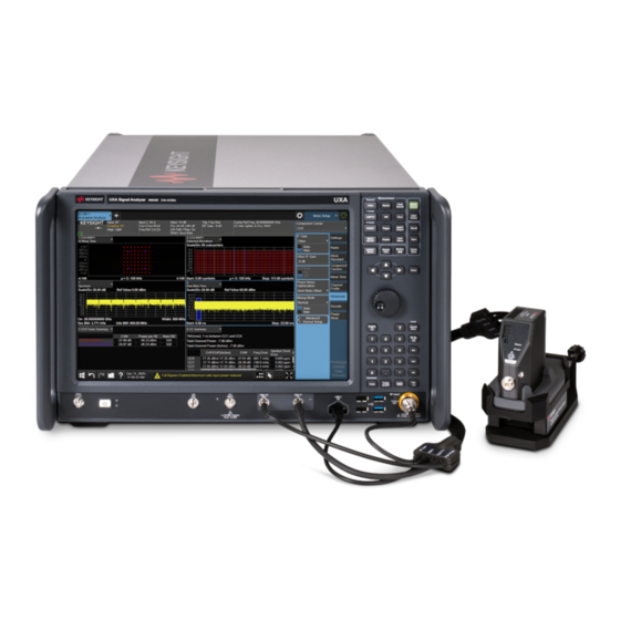
Signal analyzer
Hide thumbs
Also See for X Series:
- Service manual (671 pages) ,
- User manual (502 pages) ,
- Measurement manual (83 pages)

Related Manuals for Keysight Technologies X Series


Summary of Contents for Keysight Technologies X Series
- Page 1 Keysight X-Series Signal Analyzer N9042B IQ Streaming Option ST1 and ST2 INSTALLATION NOTE...
- Page 2 The information contained in this document is subject to change without notice. Keysight Technologies makes no warranty of any kind with regard to this material, including but not limited to, the implied warranties of merchantability and fitness for a particular purpose.
- Page 3 Option ST1 and ST2 – IQ Streaming Option ST1 and ST2 – IQ Streaming Products Affected: UXA N9042B To Be Performed By: (X) Keysight Service Center ( ) Advanced User ( ) User Estimated Installation Time: 2.0 Hours Estimated Adjustment Time: 0.0 Hours Estimated Verification Time: 1.0 Hours...
-
Page 4: Table Of Contents
Option ST1 and ST2 – IQ Streaming What you will find in this document Information......................page 5 Upgrade Contents......................page 7 Tools Required....................... page 8 Initial Instrument Functionality Check ................ page 8 Instrument Software Revision Check ................page 8 Instrument Configuration Determination .............. -
Page 5: Esd Information
Option ST1 and ST2 – IQ Streaming ESD Information Protection from Electrostatic Discharge Electrostatic discharge (ESD) can damage or destroy electronic components. All work on electronic assemblies should be performed at a static-safe workstation. Figure 1 shows an example of a static-safe workstation using two types of ESD protection: —... - Page 6 Option ST1 and ST2 – IQ Streaming — Perform work on all components at a static-safe workstation. — Keep static-generating materials at least one meter away from all components. — Store or transport components in static-shielding containers. Always handle printed circuit board assemblies by the edges. This will reduce the possibility of ESD damage to components and prevent contamination of exposed plating.
-
Page 7: Upgrade Contents
Option ST1 and ST2 – IQ Streaming Upgrade Contents Table 1 Upgrade Contents Part Number Description Quantity 0515-0372 Screw-Machine W/Crest-Cup-Con-Washer Pan-HD Torx-T10 M3X0.5 8mm-LG 0515-1946 Screw-Machine w/Patch lock 90-DEG-flat-HD Torx-T10 M3X0.5 6mm-LG 0515-2151 Screw-Machine 90-DEG-FLT-HD TORX-T6 M2X0.4 4mm-LG 0515-2332 Screw-Machine W/PATCH-LK Pan-HD Torx-T10 M3X0.5 6mm-LG 0535-0031 Nut-HEX W/Lock-Washer M3X0.5 2.4mm-THK 5.5mm-A/F 1005-1388... -
Page 8: Tools Required
Option ST1 and ST2 – IQ Streaming Tools Required — Torx Driver T-10 — Torx Driver T-20 — Multi-Bit Torque Driver — 5/8” Nut Driver — 5/16” Wrench Initial Instrument Functionality Check Power on the instrument and allow it to complete its boot up process. Verify that there are no instrument messages that would indicate that there is an issue with either the instrument hardware or software. -
Page 9: Instrument Configuration Determination
Option ST1 and ST2 – IQ Streaming Instrument Configuration Determination The following instrument condition and configuration checks need to be performed before any work on upgrading the instrument is done. This information will assist in knowing what needs to be done to the instrument and what parts will be needed. -
Page 10: Upgrade Instructions
Option ST1 and ST2 – IQ Streaming Upgrade Instructions Hardware Disassembly Dress Cover Removal 1. Turn the instrument off and disconnect the power cord. 2. Referring to Figure 2, remove the two screws (1) that attach the strap handle (2) from both sides and remove the strap handles. - Page 11 Option ST1 and ST2 – IQ Streaming Top Brace Removal 1. Referring to Figure 3, remove the fourteen flathead screws (1) and three panhead screw (2) attaching the top brace (3) to the instrument and set it aside. The fourteen flathead screws can be discarded, and they will be replaced with new ones.
- Page 12 Option ST1 and ST2 – IQ Streaming Figure 4 Remove Blank Plate Rear Panel Removal 1. Referring to Figure 5, remove the four T-10 flathead screws (1) at the corners, the eight T-20 panhead screws (2), and the twelve T-10 panhead screws (3) that attach the rear panel to the instruments.
- Page 13 Option ST1 and ST2 – IQ Streaming 2. Remove the nuts and lock washers from the two SMA connectors (4), and the nut and lock washer from the BNC connector (5). 3. Carefully remove the rear panel (6) from the instrument. Installation Note N9042-90011...
- Page 14 Option ST1 and ST2 – IQ Streaming A22 Ultra-Wideband Analog IF ODI Cable Disconnect – Option R40 1. Referring to Figure 6, if the instrument has the option R40 A22 Ultra-Wideband Analog IF assembly (1), carefully disconnect the Optical Data Interface (ODI) cable coming from the A22 assembly (2) from the center connector block (4) by sliding the blue locking tab away from the connection.
- Page 15 Option ST1 and ST2 – IQ Streaming Chassis Rear Brace Removal 1. Referring to Figure 7, remove the 4 panhead screws (1) attaching the chassis rear brace (2) to the instrument chassis sides. Figure 7 Chassis Rear Brace Removal 2. Remove the two flathead screws (3) attaching the chassis rear brace (2) to the A21 Wideband Digital IF (4).
- Page 16 Option ST1 and ST2 – IQ Streaming A21 Wideband Digital IF Removal 1. Referring to Figure 8, remove all the flexible RF cables in the marked area (1) from the A21 Wideband Digital IF (2). Figure 8 A21 Wideband Digital IF Connections Removal 2.
- Page 17 Option ST1 and ST2 – IQ Streaming Figure 9 A21 Wideband Digital IF Extraction Installation Note N9042-90011...
-
Page 18: Odi Cable Installation
Option ST1 and ST2 – IQ Streaming ODI Cable Installation The parts from this upgrade kit that will be needed for this section are listed in Table Table 2 Parts Required Part Number Description Quantity N9041-61063 Cable Assembly, Optical Firefly TX/RX N9041-20154 Heatsink, FireFly 0515-2332... - Page 19 Option ST1 and ST2 – IQ Streaming Figure 11 ODI Heatsink Thermal Pads and Gasketing ODI Cable Installation The ODI cable provided in this kit has two connectors that need to be installed on the A21 Wideband Digital IF assembly. One is blue and the other is orange. The blue connector is the receiver end, and the orange is the transmitter, so they need to be installed in the correct location on the A21 assembly, as seen in Figure...
- Page 20 Option ST1 and ST2 – IQ Streaming 1. Use the pull tab on the orange ODI cable connector to lift the locking tab of the connector up, as seen in Figure Figure 14 ODI Connector Unlocked 2. Insert the connector tool into the connector lock, as seen in Figure Figure 15 ODI Tool Inserted into Connector Lock...
- Page 21 Option ST1 and ST2 – IQ Streaming Figure 16 Lower Cable Connector into Place Figure 17 Cable Connector Lowered onto Board 4. Use the tool to slide the connector forward to engage the connector, as seen in Figure Installation Note N9042-90011...
- Page 22 Option ST1 and ST2 – IQ Streaming Figure 18 Cable Connector Slide into Place 5. Remove the connector tool from the ODI cable connector, as seen in Figure Figure 19 ODI Tool Removed 6. Press the cable connector lock down to lock it into place, as seen in Figure Installation Note N9042-90011...
- Page 23 Option ST1 and ST2 – IQ Streaming Figure 20 Cable Connector Locked into Place 7. Use the ODI connector tool to install the blue cable connector into the connector on the A21 Wideband Digital IF next to the orange cable one that was just installed, as seen in Figure 8.
- Page 24 Option ST1 and ST2 – IQ Streaming Figure 21 Install New ODI Heatsink Be sure that all the thermal pads and gasketing are properly in place on the underside of the heatsink, as seen in Figure 11, before placing the new heat sink in position. Installation Note N9042-90011...
- Page 25 Option ST1 and ST2 – IQ Streaming Reinstall A21 Wideband Digital IF 1. Referring to Figure 22, reinstall the A21 Wideband Digital IF (1), carefully moving any cables out of the way, especially if the instrument has the option R40 A22 Ultra-Wideband Analog IF (2).
- Page 26 Option ST1 and ST2 – IQ Streaming Reinstall A21 Cables – Without Option R40 1. Referring to Figure 24, reinstall the four coax cables to the A21 Wideband Digital IF, as listed in Table Figure 24 A21 Wideband Digital IF Connections - Without Option R40 Table 3 A21 Wideband Digital IF Connections - Without Option R40 A21 Port...
- Page 27 Option ST1 and ST2 – IQ Streaming Reinstall A21 Cables – With Option R40 1. Referring to Figure 25, reinstall the six coax cables to the A21 Wideband Digital IF, as listed in Table Figure 25 A21 Wideband Digital IF Connections - With Option R40 Table 4 A21 Wideband Digital IF Connections - With Option R40 A21 Port...
- Page 28 Option ST1 and ST2 – IQ Streaming Figure 26 Twinax Cable Connections - Option R40 The twinax cables have a tab that inserts into the locating slot on the board connectors, as seen Figure 27. Once the tab is inserted into the locating slot and the two center conductors are engaged, a spring loaded locking mechanism on the cable connector is used to engage with the two board connector tabs and twist to lock it in place.
- Page 29 Option ST1 and ST2 – IQ Streaming Reinstall Chassis Rear Brace – Without Option R40 1. Referring to Figure 28, reinstall the chassis rear brace (1), carefully routing the ODI cables through the round hole provided in the rear brace. Figure 28 Reinstall Chassis Rear Brace - Without Option R40 2.
- Page 30 Option ST1 and ST2 – IQ Streaming Reinstall Chassis Rear Brace – With Option R40 There are no new parts from this upgrade kit that will be needed in this section. 1. Referring to Figure 29, reinstall the chassis rear brace (1), carefully routing all the ODI cables through the two round holes provided in the rear brace.
-
Page 31: Rear Panel Configuration And Installation
Option ST1 and ST2 – IQ Streaming Rear Panel Configuration and Installation This is the part of the upgrade process that will be different depending on the instrument Configuration that was determined in the Instrument Configuration Determination section earlier in this installation note. - Page 32 Option ST1 and ST2 – IQ Streaming Figure 30 Rear Panel Assembly - Configuration A 2. Attach the mount plate (3) to the new rear panel using the two M3.0 panhead screws (4). Torque to 9 in-lbs. 3. Attach the fiber optic flange mount adapter (6) to the mount plate (3) using the M2.0 flathead screw (5).
- Page 33 Option ST1 and ST2 – IQ Streaming Figure 31 Insert ODI Cable 6. Referring to Figure 32, insert the two SMA cables through the rear panel TRIGGER 3 IN and AUX IF OUT ports and secure them with the original lock washers and nuts (1). Torque them to 10 in-lbs.
- Page 34 Option ST1 and ST2 – IQ Streaming 8. Referring to Figure 33, install the rear panel onto the instrument and secure it with the eight M4.0 panhead screws (1), the eight M3.0 panhead screws (2), and the four new M3.0 flathead screws (3).
- Page 35 Option ST1 and ST2 – IQ Streaming Rear Panel Configuration B The parts from this upgrade kit that will be needed for this section are listed in Table 6, along with the original rear panel from the instrument. Table 6 Parts Required Part Number Description...
- Page 36 Option ST1 and ST2 – IQ Streaming 4. Referring to Figure 35, insert the ODI cable (1) into the rear panel fiber optic flange mount adapter (2). The cable is keyed and can only be inserted one way. Be sure to insert it all the way, until a click is heard.
- Page 37 Option ST1 and ST2 – IQ Streaming 6. Insert the BNC cable through the rear panel EXT REF IN port and secure with the lock washer and nut (2). Torque to 21 in-lbs. 7. Referring to Figure 37, install the rear panel onto the instrument and secure it with the eight M4.0 panhead screws (1), the eleven M3.0 panhead screws (2), and the four new M3.0 flathead screws (3).
- Page 38 Option ST1 and ST2 – IQ Streaming Rear Panel Configuration C The parts from this upgrade kit that will be needed for this section are listed in Table 7, along with the original rear panel from the instrument. Table 7 Parts Required Part Number Description...
- Page 39 Option ST1 and ST2 – IQ Streaming Figure 39 ODI Cable Insertion - Configuration C 3. Referring to Figure 40, insert the two SMA cables through the instrument’s original rear panel TRIGGER 3 IN and AUX IF OUT ports and secure them with the original lock washers and nuts (1).
- Page 40 Option ST1 and ST2 – IQ Streaming Figure 41 Reinstall Rear Panel - Configuration C Installation Note N9042-90011...
-
Page 41: Instrument Button Up
Option ST1 and ST2 – IQ Streaming Instrument Button Up The parts from this upgrade kit that will be needed for this section are listed in Table Table 8 Parts Required Part Number Description Quantity 0515-1946 Patch Lock Flathead Screw – M3.0 Top Brace Installation 1. - Page 42 Option ST1 and ST2 – IQ Streaming Dress Cover Installation 1. Referring to Figure 43, carefully slide the outer cover (5) onto the instrument. Figure 43 Dress Cover Installation 2. Attach the four rear feet (4) using the four panhead screws and washers (3). Torque the screws to 21 in-lbs.
-
Page 43: Rear Panel Labels
Option ST1 and ST2 – IQ Streaming Rear Panel Labels There are three rear panel labels that need to be verified at this point: 1. Serial Number Label 2. KCC Certification Label 3. FDA Laser Label It is very important that all instructions in the section be closely followed, as legal and safety matters are involved. - Page 44 Option ST1 and ST2 – IQ Streaming In addition to attaching the FDA label to the rear panel, the month and year of the upgrade needs to be recorded on the label with a fine tip permanent marker in the mm/yyyy format. The FDA laser certification label needs to be attached in the area outlined in Figure Figure 44...
-
Page 45: Instrument Software Installation
Option ST1 and ST2 – IQ Streaming Instrument Software Installation The instrument software is required to be version A.34.00 or newer for this option to be recognized. If the instrument being upgraded does not already have a version that meets this requirement, the instrument software will need to be installed at this time. -
Page 46: Extra Parts
Option ST1 and ST2 – IQ Streaming Extra Parts There will be a number of extra parts in the kit that will not be needed for any given upgrade, depending on the configuration of the instrument, and these can be discarded. However, there is one part that needs to be returned to the owner of the instrument along with the instrument once the upgrade is completed. -
Page 47: Adjustments And Performance Verification
Automated Performance Testing Required Noise Density Residual Response Displayed Average Noise Level IF Frequency Response IF Amplitude Accuracy For assistance, contact your nearest Keysight Technologies Sales and Service Office. To find your local office access the following URL: http://www.keysight.com/find/assist Installation Note N9042-90011... -
Page 48: Odi Loopback Test
Option ST1 and ST2 – IQ Streaming ODI Loopback Test Use the following procedure to run the loopback test to verify that the newly installed streaming option hardware is working properly. 1. Connect a USB keyboard and mouse to the instrument. 2. - Page 49 Option ST1 and ST2 – IQ Streaming Figure 46 Interactive IO 6. To run the test, type the following command into the Command field: :serv:cal:piec ‘StreamingBERAlignment’ 7. Press Send Command. 8. To verify that the test passed, type the following into the Command field: :diag:cal:last:err? 9.
- Page 50 This information is subject to change without notice. © Keysight Technologies 2023 Edition 1, January 2023 N9042-90011 www.keysight.com...
Need help?
Do you have a question about the X Series and is the answer not in the manual?
Questions and answers