Table of Contents
Advertisement
Quick Links
Advertisement
Table of Contents

Related Manuals for Labgear DAT103


Summary of Contents for Labgear DAT103
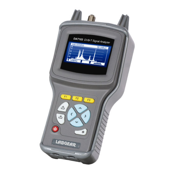
- Page 1 DAT103 DVB-T SIGNAL ANALYZER Operating Manual...
-
Page 2: Table Of Contents
TABLE OF CONTENTS TABLE OF CONTENTS........................3 GENERAL INFORMATION ....................4 1.1 I ......................4 NTRODUCTION 1.2 S ....................4 AFETY PRECAUTIONS GENERAL DESCRIPTION AND PRINCIPLE OF OPERATION........5 2.1 F .........................5 UNCTIONS 2.2 E ..................6 NVIRONMENTAL CONDITIONS 2.3 P ....................6 ACKAGE CONTENTS 2.4 S ......................6 PECIFICATION 2.4.1... -
Page 3: General Information
The analyzer allows measurement DVB-T Digital and Analogue TV signals. DAT103 can be useful in a laboratory, or in the field thanks to flexible powering options that includes an internal re-chargeable Li-ion battery. -
Page 4: General Description And Principle Of Operation
DAT103 settings including channel frequency, subcarriers number, subcarriers modulation type, guard interval, code rate and spectrum inversion are set automatically. The DAT103 can be connected to a personal computer to access additional functions. The analyzer also measures DC and AC voltages of line power supplies in TV and broadcasting distribution networks. -
Page 5: Environmental Conditions
90% at 25 ºС temperature; atmospheric pressure 84-106 kPa (630-795 mm Hg). 2.3 Package contents The analyzer package includes: a) DAT103 DVB-T Signal Analyzer ........1 pc; b) Impact resistant holster ............1 pc; c) Li-ion battery (internal) ............1 pc; d) “F”-”F” adapter..............1 pc;... -
Page 6: Construction
(Section 2.3). Check the outside of your instrument to make sure your DAT103 is free from any signs of mechanical damage. If the DAT103 has been stored in an extremely humid, hot or cold environment, allow it to acclimatize for at least for 2 hours before powering up. -
Page 7: Preparing Procedures
For operation with the external power source, connect the charger to the DC connector on the bottom panel of the DAT103 and then to mains power. Default DAT103 power for stand-alone operation is the internal battery. Push and hold key until the LCD backlight turns on to start. - Page 8 Figure 4.3.1 Figure 4.3.2 The Main menu is divided into 2 halves, to step between press the arrow. You will see the other Main menu options (Figure 4.3.2). To return to the previous line press arrow again. Function of menu are selectable with the function keys F1, F2 and F3, which are located under each icon.
-
Page 9: Level Measurement Mode
When you open LEVEL mode, you can see the channel plan name indicated by «Plan:», if one has been selected. When the LEVEL function is activated, the DAT103 measures the parameters of the TV channel, which was last selected in one of the measurement modes. This mode will be... - Page 10 to the selected channel plan. If a channel plan has not been selected, the modulation type is detected automatically. Three analog channel parameters are measured. Video carrier level at the frequency tuned. If a channel plan has been selected, the frequency tuned will follow the selected plan.
-
Page 11: Scan Measurement Mode
Signal level measurement mode tuned by frequency is shown in Figure 4.3.7. Figure 4.3.7 In this mode neither the digital D, analogue V/A ratio or C/N ratio indicators display. In the signal level measurement mode, a signal level is measured at the tuned frequency. -
Page 12: Ripple Measurement Mode
If one of the channel plans has been selected, the scanning will be performed only over the selected channels within the plan. In this case, after entering SCAN mode you will see the selected channel plan name indicated by «Plan:» for a few seconds. The navigation by ◄... -
Page 13: Expanded Spectrum Measurement Mode
4.3.5 EXPANDED SPECTRUM measurement mode This measurement is selected from the SCAN mode by pressing the F3 key. This mode displays spectrum of the input signal in scaleable frequency range. See Figure 4.3.10: Figure 4.3.10 On the screen you will see the following data: 1 –... - Page 14 5 – PerBER value 6 – PostBER value 7 – Erroneous packets after the Reed-Solomon decoder counter 8 – Command line with commands activated by F1, F2 and F3 keys 9 – Channel name (when working with selected channel plan) 10 –...
-
Page 15: Constellation Measurement Mode
Press F1 key to get detailed channel parameter information. The channel parameter table shows in Figure 4.3.12. Figure 4.3.12 On the screen you will see the following parameters: a) DVB bandwidth – channel bandwidth; b) Spectrum – spectrum type: inverted or normal; c) Guard interval –... -
Page 16: Amp Power Control
The AMP power supply is used to line power mast and distribution amplifiers, etc. directly and autonomously from your DAT103. This simplifies testing of an antenna with a preamplifier in line, to locate the best available signal in a deep fringe or poor signal area. -
Page 17: Data Manager
16 channel plans (up to 112 channels per plan), and up to 130 data log pages (with maximum number of channels). The DAT103 allows you to view the saved data in stand-alone mode or by means of a computer. - Page 18 4.4.2.1 Channel plan editing To view and edit a channel plan, select the required plan and press F1. You will see the channel plan table. The screen view is represented in the Figure 4.4.2. Figure 4.4.2 On the screen you will see the following data: 1 –...
- Page 19 Digital channel parameters: a) Band width – channel bandwidth. Can be adjusted from 1000 to 8000 kHz with 125 kHz step; b) COFDM – subcarriers modulation type. Available values: ------, QPSK, QAM16, QAM64. The «------» symbol means modulation type different from DVB-T. c) Spectrum –...
-
Page 20: Data Log Manager
4.4.2.3 Channel plan creating To create a new channel plan in auto mode, supply signal to the RF input of the Analyzer, select position of the plan in the table and press F3. If required, set an AMP power supply voltage in the screen that appears, as described in section 4.3.8, and then press F3/Exit. - Page 21 Figure 4.4.7 Figure 4.4.8 Figure 4.4.9 On the screen you will see the following data: 1 – table header line 2 – selected line 3 – channel information 4 – command line with commands activated by F1, F2 and F3 functional keys 5 –...
- Page 22 Figure 4.4.10 This table represents the parameters for the measurement results to be verified with. The table contains 13 parameters: a) Lev Vid Min. The minimum value of video carrier level for analog channel. Default value: 48 dB V. Available values: 45 to 95 dB V; b) Lev Vid Max.
-
Page 23: Setup
When creating data log pages, there will be set limits from the page, which was saved before. 4.4.3.4 Data log page erasing To erase a data log page, select the required page and press F2. The confirmation request dialog will appear. To cancel erasing, press F2. To confirm erasing of the selected page, press F1. -
Page 24: Self-Test
Analyzer operation continues. Program mem. Firmware status. This function checks the firmware status of your DAT103. If no errors detected, the Ok status is displayed. If an error has been detected, the Error status is displayed. In this... -
Page 25: Identification
Setup mode (Section 4.5). 4.8 PC communication 4.8.1 General information You can operate your DAT103 via PC. For connection to PC use USB on the bottom panel of the Analyzer. The DAT Tools software allows the following: a) measurement of video carrier level, C/N ratio and V/A ratio for analog channels and channel power for digital channels;... -
Page 26: Software Installation
The analyzer is ready for communication with DAT Tools software. 4.8.5 Firmware update The DAT103 offers the capability to update its firmware without use of any additional equipment. Each version of the firmware has its unique identification number, e.g. 13.0.0.3. The Analyzer firmware version is displayed in the Identification mode (section 4.7). -
Page 27: Channel Template Edit
Press «Start» button. If your Analyzer functions properly, USB port cable connected correctly and the firmware updating file is compatible with the DAT103, the process of program updating onto your Analyzer will automatically start. The Analyzer must be powered from an external power source. - Page 28 You will find them in the folder “TvSystems” in the place all user data are stored; d) Load or Save Channel templates to DAT103. Channel templates include the following parameters: a) Audio carrier. Audio carrier frequency offset from channel video carrier. Uses for V/A ratio measurement.
-
Page 29: Maintenance
Quality connectors and test leads are a sound investment in long reliable analyzer life. Clean Annually; remove your DAT103 from its soft plastic holster, hold upside down and brush gently with a small dry horsehair or similar brush - so that any foreign materials fall away. -
Page 30: Storage
800 mm Hg). Cargo holds, railway cars, containers, and truck beds, utilized for shipment of the DAT103 should be free from any traces of cement, coal, chemicals, etc. When shipped by air the products should be kept in aircraft sealed compartments. - Page 31 Copyright© 2013 LABGEAR Australia 42 Brunel Rd. Seaford VIC 3198 Australia Tel:(03)9776 4763 Rev. 1.3 22.02.13...
Need help?
Do you have a question about the DAT103 and is the answer not in the manual?
Questions and answers