Table of Contents
Advertisement
Quick Links
Advertisement
Table of Contents

Related Manuals for Cleco 47BC B Series


Summary of Contents for Cleco 47BC B Series
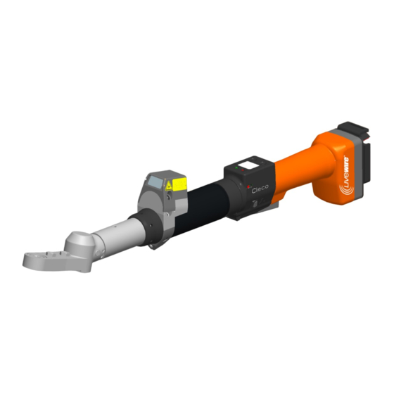
- Page 1 Instruction Manual P1962E/EN 2012-03 47BC/BT…B… Cordless EC Tool For additional product information visit our website at: https://dotcotool.com/product-category/cleco-tools/cleco-livewire-assembly-tools/cleco-livewire-crowfoot- series-nutsetters/...
- Page 2 For this Instruction Manual This Instruction Manual is the translation of the Original Instruction Manual intended for all persons who work with this tool but do not do any programming work. The Instruction Manual • provides important notes for safe and effective use. •...
- Page 3 Identification text: 47BC/BT represents all models of the cordless EC tool as described here. represents all models of the power supply as described here: Accupack or Power Module RF15.4 represents the Wireless Fidelity IEEE802.15.4 represents the interchangeable memory module LiveWire Memory Chip ➔...
- Page 4 P1962E/EN 2012-03 62a_ Deckblatt en.fm, 29.02.2012...
-
Page 5: Table Of Contents
Contents Safety Warnings and notes................7 Basic requirements for safe working practices ........8 Operator training................... 8 Personal protective equipment ............. 8 Designated use..................9 Codes and standards................9 Noise and vibration ................9 Scope of supply, transport and storage Items supplied.................. - Page 6 Service schedule ................39 Lubricants ................... 40 Troubleshooting Spare parts 10.1 Gear + Head T2X, T3X, T4X .............. 50 10.2 Head T2X.................... 52 10.3 Head T3X.................... 54 10.4 Head T4X.................... 56 10.5 Socket for head T2X, T3X, T4X, optional ........... 58 10.6 Gear + Head C1, C3 ................
-
Page 7: Safety
Safety Safety Warnings and notes Warning notes are identified by a signal word and a pictogram: • The signal word describes the severity and the probability of the impending danger. • The pictogram describes the type of danger. WARNING! Indicates a potentially hazardous situation which, if not avoided, could result in serious injury. -
Page 8: Basic Requirements For Safe Working Practices
Inspect sockets for visible damage and cracks. Replace damaged sockets immediately. ➔ Disconnect the 47BC/BT from the PS before replacing the sockets. ➔ Only use socketsbits from Cleco, see 10.9 Socket for C1, C3, optional, page 66. ➔ Do not attach sockets on the head aslant. ➔... -
Page 9: Designated Use
Safety Designated use The 47BC/BT is designed exclusively for fastening and releasing threaded fasteners. • The communication with the controller is allowed only over the following interface ports: Do not use it in Types Communications IrDA interface port of the tool holder, order no. 935290 47BCR…/47BTR…... -
Page 10: Scope Of Supply, Transport And Storage
Scope of supply, transport and storage Scope of supply, transport and storage Items supplied Check shipment for transit damage and ensure that all items have been supplied: 1 47BC/BT 1 This instruction manual 1 Declaration of Conformity 1 Factory test certificate for transducers 1 Machine capability analysis Transport Transport and store the 47BC/BT in the original packaging. -
Page 11: Product Description
Product description Product description General description • Sturdy, brushless motor with resolver. Shutoff is torque/angle-controlled. • LCD display with information on status, torque and angle. • Green OK and red NOK LED display provides information on the current fastening result. •... -
Page 12: Operation And Functional Elements
Product description Operation and functional elements This chapter describes operational and functional elements and their tasks in the order of their respective item nos. 1 <F2> 1 <F1> Item Designation Function keys <F1>, <F2> LED display Start button Reverse switch IrDA (infrared interface port) Set torque –... - Page 13 Product description 3.2.1 Function keys Left function key <F1> • Confirm error message Press once. ➔ Programmable: Depending on how the key is programmed, actions can be carried out by pressing it briefly. • Exit menu Press for two seconds. ➔...
- Page 14 Product description • It activates the barcode scanner—only for types of the 47BC...S/47BT...S series. Press the start button all the way down. ➔ 3.2.4 Reverse switch The reverse switch changes the rotation direction of the 47BC/BT: Clockwise rotation – for screwing in screws Press reverse switch as far as it will go.
- Page 15 Product description 3.2.8 Power supply See Instruction manual battery pack / Instruction manual Power Module PM48. 3.2.9 LCD display See 7 LCD display, page 21 3.2.10 Barcode scanner For tools of the 47BC...S/47BT...S series, the built-in barcode scanner is a class 2 laser scanner with a wavelength of 650 nm.
-
Page 16: Accessories
Accessories 3.2.11 Radio interface port Tools are equipped with an wireless interface port in addition to the IrDA interface port. Type Communication necessary counterpart 47BC...R/ RF868 MHz Base station order no. 961300 47BT...R 47BC...X/ WLAN Standard IEEE 802.11b Access Point according to Standard 47BT...X IEEE 802.11b 47BCY…/... -
Page 17: Before Initial Operation
Before initial operation Power Module PM48 Order no. 961350 Order no. 961327 – Europe Order no. 961461PT – USA/Canada Order no. 961462PT – Japan Adapter cable Order no. 961341-030 – 3 m Order no. 961341-060 – 6 m Order no. 961341-080 – 8 m Order no. -
Page 18: Ambient Conditions
Before initial operation Ambient conditions Ambient temperature 0 °C (32 °F) to maximum +40° C (+104° F) Humidity 0 to 80 %, not with dew Working height up to 1000 m above sea level Charging the battery pack Battery pack is only partly charged when delivered. Charge fully before first use. -
Page 19: First Operation
First Operation Inserting LMC Carefully insert LMC according to the illus- ➔ tration. Tighten the screws (M4, DIN 912). ➔ Insert the battery pack. ➔ Fig. 5-1: Changing the LMC First Operation Carrying out the rundown Make sure that the battery pack is securely installed before operating the 47BC/BT. The 47BC/BT is now ready for use. - Page 20 First Operation Operating LCD display Function status display Sleep Data transmission not possible Manual switch from Sleep to Active: Press down start button and hold down for approx. 1 second. To switch off the 47BC/BT manually, pull out the battery. P1962E/EN 2012-03 91b_1_5 en bedingt.fm, 29.02.2012...
-
Page 21: Lcd Display
LCD display LCD display The LCD display on the tool is divided into the result display, status display, operating menu and system error messages. Result display The LCD display consists of a three lines, each with 6 characters, to display the status, torque and angle. The result display is updated after the rundown T12.00 ends. - Page 22 LCD display No other status messages take priority. Ready The tool is ready. Number of remaining rundowns that can still be carried out until the rundown data memory Remain is full and the rundown data have to be transmitted to the control. Tool waits for action after every fastening (only for types of the 47BC/BT) Open Press the start button.
- Page 23 LCD display Error in last data synchronization with the control. Sync Synchronize the tool with the control once again. Error ➔ Tool has not yet been synchronized with a control. Tool Synchronize the tool with the control for the first time. ➔...
-
Page 24: Operating Menu
LCD display Operating menu 7.3.1 General The operating menu on the tool is divided into a main menu and submenus. You can navigate through the menus using the two function keys below the LCD display. In the following description, <F1> is used for the left function key and <F2>... - Page 25 LCD display 7.3.2 Structure Main Administration Administration Diagnostics Date / Time Set position Counter display Scanner Serial number RF settings Software version Back Servo Emergency strategy Back Diagnostics TQ calibration TQ measurement Angle encoder Voltages Speed Back Set position Next position Reset Linking Back Scanner...
- Page 26 LCD display 868MHz Wireless module version Channel Network ID Tool ID Power Back RF15.4 / IEEE802.15.4 Channel PAN ID Tool ID Power Encryption Wireless module Serial no. Wireless module version Signal RSSI Back 7.3.3 Main menu Administration – General items such as Date/Time, Counter display, etc. >Main Admini strati...
- Page 27 LCD display 7.3.4 Administration submenu Date/Time Time Displays the tool system time. 07:47 The system time can be displayed in US or European format. 30.09 Refer to "Setting the system time on the control" under ➔ Administration\Date\Time. Counter display Counte The tool counter display is incremented after each rundown throughout the service life of the tool.
- Page 28 LCD display Emergency strategy on. Emerge If the emergency strategy is enabled and Linking is disabled, the fastening parameters of the Strate last selected Application are used. For Linking operating mode, all steps are used with the corresponding parameters of the last selected Tightening Group. The memory of the tool stores data from up to 512 rundowns.
- Page 29 LCD display Voltages Voltage Second line: Current battery voltage. To ensure high utilization potential, this voltage is V26.40 monitored continuously during fastening operation. If the voltage drops below limit, a U19.00 warning output on the tool. Third line: Programmed value. (under Tool) This can be changed using the control Speed...
- Page 30 LCD display 7.3.8 WLAN wireless transmission submenu – only for types of the 47BCX…/47BTX…, 47BCY…/47BTY…/ series The WLAN RF settings submenu shows the settings being used. If no actions are carried out, the menu is automatically exited after 60 seconds. Programming the RF settings for WLAN data transmission is described in the programming manual of the control.
- Page 31 LCD display 7.3.9 868 MHz wireless transmission submenu – only for types of the 47BCR…/ 47BTR… series The 868 MHz RF settings submenu shows the settings being used. If no actions are carried out, the menu is automatically exited after 60 seconds. Programming the RF settings is described in the control programming manual.
- Page 32 LCD display Displays the transmission power and allows you to configure settings. Power 25 mW <F1>: Activate a lower transmission power. ➔ <F2>: Activate a higher transmission power. ➔ Press the start button or <F2> longer than 2 ➔ seconds to accept the select and display the next menu item. Press <F1>...
- Page 33 LCD display The PAN ID consists of 4 hexadecimal numbers. A maximum of 65 535 different PAN IDs are therefore available. Cursor flashes under the number to be modified: 1234 <F1>: lower number ➔ <F2>: higher number. ➔ Press the start button: ➔...
- Page 34 LCD display Display Transmission power Transmission power 0.63 0.40 0.25 0.10 Displays the data transmission encryption. RF15.4 AES = Advanced Encryption Standard, code length = 128 bit. On and Off are available for selection. Start button>: show encryption (default: off). ➔...
-
Page 35: System Error Messages
LCD display Displays the current RSSI value. RF15.4 RSSI = Received Signal Strength Indication, indication of the reception strength of wireless Signal communication systems. The lower the RSSI value, the poorer the signal strength. Value range: 0 (very good) to -100 (no reception). If the tool is positioned in the direct vicinity of the base station and the transmission power is preset to maximum, the RSSI value should be between -30 and -55. - Page 36 LCD display Collective servo error caused by hardware. Servo Return tool to Sales & Service Centers for repair. Error ➔ Other The current set point has been exceeded. Servo There may be a short circuit. Error Return tool to Sales & Service Centers for repair. ➔...
- Page 37 LCD display Tool memory could not be read. Tool Return tool to Sales & Service Centers for repair. Error ➔ Ident Two-stage start button defective. Tool Return tool to Sales & Service Centers for repair. Error ➔ Start Transducer reference voltage error. Transd Return tool to Sales &...
- Page 38 LCD display P1962E/EN 2012-03 91c_LCD en bedingt.fm, 29.02.2012...
-
Page 39: Maintenance
Maintenance Maintenance Cleaning instructions For tools with a built-in barcode scanner, the window must be free of dirt. Clean it regularly—or immediately, if it becomes dirty—using a damp cloth and a conventional window ➔ cleaner. Do not use acetone for cleaning. A dirty window may make it impossible to read barcodes. Service schedule Only personnel authorized by Cooper Power Tools are permitted to perform maintenance. -
Page 40: Lubricants
Maintenance Lubricants For smooth function and a long service life, use of the correct grease types according to the table is essen- tial. Grease lubricants according to DIN51502 /ISO3498 Order no. Packing unit Saunders 51502 Enterprises, [ kg ] Inc. Synthetic Lubricants Microlube... -
Page 41: Troubleshooting
Troubleshooting Troubleshooting Problem Possible cause Action General – Tool Tool does not start if Backoff speed parame- Adjust the backoff speed value in the Standard ➔ reverse switch is active. ter is set to 0 rpm. Application Builder screen of the controller. Tool light not active. - Page 42 Troubleshooting Problem Possible cause Action WLAN data communication between controller and tool No WLAN IP address of tool is not Check in the Communication/Tool screen of ➔ communication entered correctly on the the controller that the IP address of the tool is between controller and controller.
- Page 43 Troubleshooting Problem Possible cause Action 868 MHz data communication between controller and tool No serial communication Wrong serial cable is Use a null modem cable (crossed). ➔ is possible between the used. controller and the base Wrong port is selected In the Communication/Tool screen of the con- ➔...
- Page 44 Troubleshooting Problem Possible cause Action 868 MHz data communication between controller and tool No Ethernet communi- Wrong Ethernet cable is A crossover cable is required if the base station ➔ cation is possible used. is directly connected to the controller. If the base between the controller station is connected to a switch, a standard and the base station.
- Page 45 Troubleshooting Problem Possible cause Action 868 MHz data communication between controller and tool RF communication is Distance between base If channel 1 is selected, the distance can be up to partly interrupted. station and tool is too 30 m. If channel 2 or 3 is selected, the distance can great.
- Page 46 Troubleshooting Problem Possible cause Action RF15.4 data communication between controller and tool No serial communication Wrong serial cable is Use a null modem cable (crossed). ➔ is possible between the used. controller and the base Wrong port is selected In the Communication/Tool screen of the con- ➔...
- Page 47 Troubleshooting Problem Possible cause Action RF15.4 data communication between controller and tool RF communication is Distance between base If channel 1 is selected, the distance can be up to partly interrupted. station and tool is too 30 m. If channel 2 or 3 is selected, the distance can great.
- Page 48 Troubleshooting P1962E/EN 2012-03 91e_Trouble shooting en bedingt.fm, 29.02.2012...
-
Page 49: Spare Parts
Spare parts Note Use only original CLECO spare parts. Failure to comply can result in reduced power and increased service requirements. If spare parts not manufactured by us are installed, the tool manufacturer is entitled to deny any warranty claims. -
Page 50: Gear + Head T2X, T3X, T4X
Spare parts 10.1 Gear + Head T2X, T3X, T4X 47BT…20T2 47BT…30T3 47BT…40T4 933027 Changes made since last issuance 2009-05 8.3 Lubricants, page 40 P1962E/EN 2012-03 62f_Ersatzteile en.fm, 29.02.2012... - Page 51 Spare parts 1) Order no. 2) Quantity 3) Dimensions Recommended spare part for every 5 tools ● see table, Page 50 P1962E/EN 2012-03 62f_Ersatzteile en.fm, 29.02.2012...
-
Page 52: Head T2X
Spare parts 10.2 Head T2X 540395 8.3 Lubricants, page 40 P1962E/EN 2012-03 62f_Ersatzteile en.fm, 29.02.2012... - Page 53 Spare parts 1) Order no. 2) Quantity 3) Dimensions Recommended spare part for every 5 tools ● The ordered socket is assembled factory-set. See 10.5 Socket for head T2X, T3X, T4X, optional, page 58 ** Not included in T2X, quantity varies due to production P1962E/EN 2012-03 62f_Ersatzteile en.fm, 29.02.2012...
-
Page 54: Head T3X
Spare parts 10.3 Head T3X 540395 8.3 Lubricants, page 40 P1962E/EN 2012-03 62f_Ersatzteile en.fm, 29.02.2012... - Page 55 Spare parts 1) Order no. 2) Quantity 3) Dimensions Recommended spare part for every 5 tools ● The ordered socket is assembled factory-set. See 10.5 Socket for head T2X, T3X, T4X, optional, page 58 ** Not included in T3X, quantity varies due to production P1962E/EN 2012-03 62f_Ersatzteile en.fm, 29.02.2012...
-
Page 56: Head T4X
Spare parts 10.4 Head T4X 540395 8.3 Lubricants, page 40 P1962E/EN 2012-03 62f_Ersatzteile en.fm, 29.02.2012... - Page 57 Spare parts 1) Order no. 2) Quantity 3) Dimensions Recommended spare part for every 5 tools The ordered socket is assembled factory-set. See 10.5 Socket for head T2X, T3X, T4X, optional, page 58 ** Not included in T4X, quantity varies due to production P1962E/EN 2012-03 62f_Ersatzteile en.fm, 29.02.2012...
-
Page 58: Socket For Head T2X, T3X, T4X, Optional
Spare parts 10.5 Socket for head T2X, T3X, T4X, optional Index Hexagon socket size Flush Extended 1/4" Extended 1/2" Extended 3/4" Extended 1" (6,35 mm) (12,7 mm) (19 mm) (25,4 mm) Head T2X 1/4” KS2EA0… KS2EA2… KS2EA4… KS2EA6… KS2EA8… 5/16” KS2EB0…... - Page 59 Spare parts Index Hexagon socket size Flush Extended 1/4" Extended 1/2" Extended 3/4" Extended 1" (6,35 mm) (12,7 mm) (19 mm) (25,4 mm) Head T4X 1/2” KS4EE0… KS4EE2… KS4EE4… KS4EE6… KS4EE8… 9/16” KS4EF0… KS4EF2… KS4EF4… KS4EF6… KS4EF8… 5/8” KS4EG0… KS4EG2… KS4EG4…...
-
Page 60: Gear + Head C1, C3
Spare parts 10.6 Gear + Head C1, C3 47BC…30C1 301071 15° 47BC…30C3 301072 30° 933027 8.3 Lubricants, page 40 P1962E/EN 2012-03 62f_Ersatzteile en.fm, 29.02.2012... - Page 61 Spare parts 1) Order no. 2) Quantity 3) Dimensions Recommended spare part for every 5 tools ● See table *, page 60 P1962E/EN 2012-03 62f_Ersatzteile en.fm, 29.02.2012...
-
Page 62: Head 301071 (C1)
Spare parts 10.7 Head 301071 (C1) Note: ALWAYS replace Bevel Gear and Bevel Pinion in pairs since both should wear equally. 541444, 541445 8.3 Lubricants, page 40 P1962E/EN 2012-03 62f_Ersatzteile en.fm, 29.02.2012... - Page 63 Spare parts 1) Order no. 2) Quantity 3) Dimensions Recommended spare part for every 5 tools ● The ordered socket is assembled factory-set. See 10.9 Socket for C1, C3, optional, page 66 P1962E/EN 2012-03 62f_Ersatzteile en.fm, 29.02.2012...
-
Page 64: Head 301072 (C3)
Spare parts 10.8 Head 301072 (C3) Note: ALWAYS replace Bevel Gear and Bevel Pinion in pairs since both should wear equally. 541444, 541445 8.3 Lubricants, page 40 P1962E/EN 2012-03 62f_Ersatzteile en.fm, 29.02.2012... - Page 65 Spare parts 1) Order no. 2) Quantity 3) Dimensions Recommended spare part for every 5 tools ● The ordered socket is assembled factory-set. See 10.9 Socket for C1, C3, optional, page 66 P1962E/EN 2012-03 62f_Ersatzteile en.fm, 29.02.2012...
-
Page 66: Socket For C1, C3, Optional
Spare parts 10.9 Socket for C1, C3, optional Index Hexagon Socket Size Flush Extended 1/2" Extended 3/4" (12,7 mm) (19 mm) 1/4" CSEA01 CSEA41 CSEA61 3/8" CSEC01 CSEC41 CSEC61 7/16" CSED01 CSED41 CSED61 1/2" CSEE01 CSEE41 CSEE61 9/16" CSEF01 CSEF41 CSEF61 7 mm CSMA01... -
Page 67: Tool Holder
Spare parts 10.10 Tool holder Order no. IrDA For tool … 935290 × 935303 935170 917735 47BT 935292 935395 – – – – 935999 × 935303 935170 917735 47BC 935942 935998 – – – – 1) Order no. 2) Quantity 3) Dimensions Recommended spare part for every 5 tools ●... - Page 68 Spare parts P1962E/EN 2012-03 62f_Ersatzteile en.fm, 29.02.2012...
-
Page 69: Technical Data
Technical data Technical data 11.1 Dimensions 47BT…20T2 without scanner … with scanner L1-1 L1-2 L1-3 L3 L4 L1-1 L1-2 L1-3 L3 L4 47BTB20T2 554,8 562,9 – – – 47BTRSB20T2 47BTRB20T2 47BTXSB20T2 568,8 576,9 14,2 43 18 47BTXB20T2 568,8 576,9 14,2 –... - Page 70 Technical data 47BT…30T3 without scanner … with scanner L1-1 L1-2 L1-3 L3 L4 L1-1 L1-2 L1-3 L3 L4 47BTB30T3 546,8 554,9 – – – 47BTRSB30T3 47BTRB30T3 47BTXSB30T3 558,8 566,9 14,2 43 18 47BTXB30T3 558,8 566,9 14,2 – – 47BTYSB30T3 47BTYB30T3 47BTZSB30T3 47BTZB30T3 47BC…40T4 without scanner...
- Page 71 Technical data 47BC…30C1 without scanner … with scanner L1-1 L1-2 L1-3 L3 L4 L1-1 L1-2 L1-3 L3 L4 47BCB30C1 623,8 631,9 – – – 47BCRSB30C1 47BCRB30C1 47BCXSB30C1 637,8 645,9 14,2 43 65 47BCXB30C1 637,8 645,9 14,2 – – 47BCXSB30C1 47BCYB30C1 47BCYSB30C1 47BCZB30C1 47BCZSB30C1...
-
Page 72: Dimensions Of Tool Holder 935290 / 935395 (Optional)
Technical data 11.2 Dimensions of tool holder 935290 / 935395 (Optional) 11.3 Dimensions of tool holder 935999 / 935998 (Optional) P1962E/EN 2012-03 62g_TechnDaten en.fm, 29.02.2012... -
Page 73: Performance Data
Technical data 11.4 Performance Data Parameter Tool Memory Type Screw size Weight without Recommended Free speed Calibration data Static Cur- Accu torque range rent Factor Accu- PM48, Accu- Torque Angle pulses ft.-lbs (Nm) pack 26 V pack 44 V (nominal) (Resolver) max. -
Page 74: Electrical Data
Technical data Parameter Tool Memory Type Screw size Weight without Recommended Free speed Calibration data Static Cur- Accu torque range rent Factor Accu- PM48, Accu- Torque Angle pulses ft.-lbs (Nm) pack 26 V pack 44 V (nominal) (Resolver) max. min. ft.-lbs (Nm) ¹/degrees Nm/A... - Page 75 Technical data 11.5.3 IrDA interface port Features Data Supply voltage 5.0 V (4.8 to 5.5 V) Power consumption 0.30 VA Maximum current 11 mA Transmission rate 57.6 Kbps Parity Bit None Data Bit 8 bit Stop Bit 1 bit Error check 11.5.4 Scanner Features...
- Page 76 Technical data 11.5.5 RF15.4 data transmission Features Data Frequency 2,4 GHz ISM Channels Modulation 0-QPSK (DSSS) Output power 1 mW (0 dBm) Sensitivity (BER < 10-3) -92 dBm Wireless transmission rate 57.6 kbps Range up to 10 m (98.4”) Standards ETSI EN 300 328 V1.7.1 EN 301489-1 V1.6.1 EN 301489-3 V1.4.1...
- Page 77 Technical data 11.5.7 WLAN data transmission The WLAN data transmission functions may vary depending on the tool configuration. Serie 47BTX…/47BCX… Features Data Standard IEEE 802.11b Safety • 64/128 bit encryption WPA/WPA2/802.11 • 128 bit TKIP/CCMP encryption • 802.1x EAP authentication (LEAP, PEAP, TTLS, GTC, MD5, OTP, PAP, CHAP, MSCHAP, MSCHAPv2, TTLS MSCHAPv2)·...
-
Page 78: Service
Service Series 47BAY… Features Data Standard IEEE 802.11a/b/g Safety • 64/128 bit encryption WPA/TKIP • WPA2-AES(CCMP) • LEAP, PEAP Range Typically up to 50 m (164’ 0.5”) Channels • 2,4 GHz: 1 – 13 • 5 GHz: 36, 40, 44, 48 (52, 56, 60, 64, 100, 104, 108, 112, 116, 120, 124, 128, 132, 136, 140) Transmission rate:... -
Page 79: Recalibration
The type-specific calibration data is saved on the integrated screw electronic system in the delivery state of the Cleco tool. If service is required to change the torque transducer, the screw electronic system or if a recalibration is required, please send the Cleco tool to Sales & Service Centers. This will ensure that after the service work, any required calibration data update is carried out properly. - Page 80 Sales & Service Centers Note: All locations may not service all products. Please contact the nearest Sales & Service Center for the appropriate facility to handle your service requirements. Dallas, TX Detroit, MI Houston, TX Lexington, SC Apex Tool Group Apex Tool Group Apex Tool Group Apex Tool Group...
Need help?
Do you have a question about the 47BC B Series and is the answer not in the manual?
Questions and answers