Table of Contents
Advertisement
Quick Links
HOLEMAKER PRO 50
HOLEMAKER HMPRO35-T3
HOLEMAKER PRO 50
Holemaker Portable Magnetic Drilling Machine
OPERATOR'S MANUAL
Holemaker Portable Magnetic Drilling Machine
Holemaker Portable Magnetic Drilling Machine
OPERATOR'S MANUAL
OPERATOR'S MANUAL
BEFORE USE
BEFORE USE
EYE PROTECTION
REQUIRED
EYE PROTECTION
REQUIRED
S
r e
a i
# l
Ver: 1.02 21/02/2020
Ver: 1.10
14/08/2015
S
r e
a i
# l
Ver: 1.10
14/08/2015
WARNING!
,
ENSURE EVERYONE USING THIS MACHINE READS AND UNDERSTANDS
WARNING!
ALL SAFETY AND OPERATING INSTRUCTIONS IN THIS MANUAL
OPERATOR'S MANUAL
,
ENSURE EVERYONE USING THIS MACHINE READS AND UNDERSTANDS
ALL SAFETY AND OPERATING INSTRUCTIONS IN THIS MANUAL
P
R
P
R
HEARING PROTECTION
NEVER PLACE
REQUIRED
FINGERS NEAR
CUTTING AREA OR
DRILLING MACHINE
MACHINE ARBOR
HEARING PROTECTION
NEVER PLACE
REQUIRED
FINGERS NEAR
WITH ELECTROMAGNETIC BASE
CUTTING AREA OR
MACHINE ARBOR
ul. Elewatorska 23/1, 15-620 Białystok, Poland
Phone: +48 85 678-34-95, Fax: +48 85 662-78-77
www.promotech.eu
O
3
6
T
3
O
3
6
T
3
LINE VOLTAGE
PRESENT
LINE VOLTAGE
PRESENT
D
a
e t
f o
P
r u
h c
a
D
a
e t
f o
P
r u
h c
a
e-mail:
info@promotech.eu
.
.
BEWARE OF
ROTATING
MACHINE PARTS
BEWARE OF
ROTATING
MACHINE PARTS
e s
e s
Advertisement
Table of Contents

Related Manuals for Itm HOLEMAKER HMPRO35-T3


Summary of Contents for Itm HOLEMAKER HMPRO35-T3
- Page 1 HOLEMAKER PRO 50 HOLEMAKER HMPRO35-T3 HOLEMAKER PRO 50 Holemaker Portable Magnetic Drilling Machine OPERATOR’S MANUAL Holemaker Portable Magnetic Drilling Machine Holemaker Portable Magnetic Drilling Machine OPERATOR’S MANUAL OPERATOR’S MANUAL WARNING! BEFORE USE ENSURE EVERYONE USING THIS MACHINE READS AND UNDERSTANDS...
-
Page 2: Table Of Contents
HMPRO35-T3 OPERATOR’S MANUAL LIMITED WARRANTY Industrial Tool & Machinery Sales (hereinafter referred to as ITMS) will, within twelve (12) months from the original date of purchase, repair or replace any goods found to be defective in materials or workmanship. This warranty is void if the item has been damaged by accident, neglect, improper service or other causes not arising out of defects in materials or workmanship. -
Page 3: General Information
HMPRO35-T3 OPERATOR’S MANUAL PRO 36 T3 1. GENERAL INFORMATION 1.1. Application The PRO 35 T3 is a drilling machine designed to drill holes with diameters of up to 35 mm to a depth of up to 51 mm by using annular cutters. The electromagnetic base allows the drilling machine to be fixed to ferromagnetic surfaces with a force that ensures operator safety and proper machine operation. -
Page 4: Equipment Included
HMPRO35-T3 OPERATOR’S MANUAL PRO 36 T3 1.3. Equipment included Drilling machine with cooling 1 unit system bottle and chip guard Plastic box 1 unit Handle 3 units Safety strap 1 unit 4 mm hex wrench with handle 1 unit – Operator’s Manual 1 unit www.itmtools.com.au... -
Page 5: Dimensions
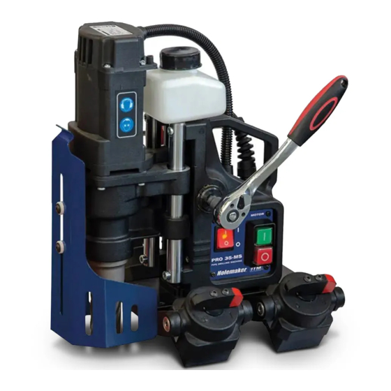
HMPRO35-T3 OPERATOR’S MANUAL PRO 36 T3 1.4. Dimensions 179 mm (7-1/16’’) 314 mm (12-3/8’’) 1.5. Design Cooling system bottle Bottle valve lever Feed shaft Carrying handle MOTOR start button Control panel Spindle with arbor Chip guard Electromagnetic base MOTOR stop Electromagnetic base button Opening for safety strap... -
Page 6: Safety Precautions
HMPRO35-T3 OPERATOR’S MANUAL PRO 36 T3 2. SAFETY PRECAUTIONS 1. Before starting, read this Operator’s Manual and complete proper occupational safety and health training. 2. Use the machine only in applications specified in this Operator’s Manual. 3. The machine must be complete and all parts must be genuine and fully functional. 4. - Page 7 HMPRO35-T3 OPERATOR’S MANUAL PRO 36 T3 20. Use the safety strap in all work positions. Attach the machine to a fixed structure by fastening the strap through the opening in the machine body. When working in horizontal position fasten the strap to the carrying handle. Never insert the strap into the buckle from the front.
-
Page 8: Startup And Operation
HMPRO35-T3 OPERATOR’S MANUAL PRO 36 T3 3. STARTUP AND OPERATION 3.1. Installing, removing, and operating the annular cutter Unplug the machine from the power source, and then rotate the handles to the right (1, Fig. 1) to raise the motor. Wear protective gloves and insert the proper pilot pin into the annular cutter (2). - Page 9 HMPRO35-T3 OPERATOR’S MANUAL PRO 36 T3 Fig. 2 shows how annular cutters work. As the cutter drills into the workpiece, the pilot pin retracts and the coolant gets into the cutter. After the drilling, the tightened spring causes the slug core to be pushed out. Arbor Spring Annular cutter...
-
Page 10: Installing And Removing The Cooling System Bottle
HMPRO35-T3 OPERATOR’S MANUAL PRO 36 T3 3.2. Installing and removing the cooling system bottle Rotate the handles (1, Fig. 4) to raise the motor. Next, place the cooling system bottle on the machine (2), and then attach the bottle hose to the hose fitting (3). To remove the bottle, first detach the hose from the fitting and raise the motor. -
Page 11: Preparing
HMPRO35-T3 OPERATOR’S MANUAL PRO 36 T3 3.3. Preparing Before starting, clean steel parts, including the arbor, from anti-corrosion coating used to preserve the machine for storage and transport. Screw the handles into the feed shaft. The machine can allow use by a left-handed person or in places hard to reach. - Page 12 HMPRO35-T3 OPERATOR’S MANUAL PRO 36 T3 Vertical drilling Inverted drilling CORRECT INCORRECT ✓ Horizontal drilling Fig. 5. Protecting the machine from falling by using the safety strap Rotate the handles to the left to place the cutter above the workpiece. When working in the position from Fig.
-
Page 13: Drilling
HMPRO35-T3 OPERATOR’S MANUAL PRO 36 T3 3.4. Drilling Start the motor with the green MOTOR button. Then, slowly rotate the handles to the left to lower the cutter to the workpiece, and start drilling. Drill the hole in one pass. After the annular cutter drills through the workpiece, the slug core is pushed out with a large force. -
Page 14: Replacing The Motor Brushes
HMPRO35-T3 OPERATOR’S MANUAL PRO 36 T3 3.5. Replacing the motor brushes Check the condition of the carbon brushes every 100 work hours. To do this, unplug the machine from the power source, and unscrew the cover (1, Fig. 6). Next, unscrew the pressing plate (2), and then remove the brush holder (3) and the brush (4). -
Page 15: Wiring Diagram
HMPRO35-T3 OPERATOR’S MANUAL PRO 36 T3 5. WIRING DIAGRAM 4. WIRING DIAGRAM This document is protected by copyrights. www.itmtools.com.au Copying, using, or distributing without permission of PROMOTECH is prohibited. -
Page 16: Www.itmtools.com.au
HMPRO35-T3 OPERATOR’S MANUAL Parts list PRO 36 T3 v.4.05 ITEM PART NUMBER DESCRIPTION Q-TY SKR-000010 PLASTIC BOX KLC-000036 4 MM HEX WRENCH WITH HANDLE PAS-000007 SAFETY STRAP 250 www.itmtools.com.au This document is protected by copyrights. Copying, using, or distributing without permission of PROMOTECH is prohibited. - Page 17 HMPRO35-T3 OPERATOR’S MANUAL Parts list PRO 36 T3 v.4.05 www.itmtools.com.au This document is protected by copyrights. Copying, using, or distributing without permission of PROMOTECH is prohibited.
- Page 18 HMPRO35-T3 OPERATOR’S MANUAL Parts list PRO 36 T3 v.4.05 ITEM PART NUMBER DESCRIPTION Q-TY SZN-0212-10-02-00-2 POWER CORD 230V 3x1.5 WITH STRAIN RELIEF ASSY (EU) SZN-0212-10-02-00-1 POWER CORD 230V 3x1 WITH STRAIN RELIEF ASSY (AU) SZN-0075-00-51-00-5 POWER CORD 120V 3x2.08 WITH STRAIN RELIEF ASSY (US) PWD-0212-10-02-00-6 POWER CORD 230V 3x1.5 WITH STRAIN RELIEF ASSY (INDIA) DZW-0212-12-00-00-0...
- Page 19 HMPRO35-T3 OPERATOR’S MANUAL Parts list PRO 36 T3 v.4.05 ITEM PART NUMBER DESCRIPTION Q-TY LOZ-000048 BALL BEARING 25x47x12 KNC-0234-00-10-00-0 HOSE FITTING WKR-000241 SELF-TAPPING SCREW 4x20 SCZ-000008 MOTOR BRUSH 6x9x17 SCT-0271-03-06-00-0 BRUSH HOLDER LOZ-000053 BALL BEARING 8x22x7 PKR-0440-03-02-00-1 MOTOR COVER PRS-000070 SEAL 25x37x7 LST-0271-02-01-02-1 GEAR RACK...
Need help?
Do you have a question about the HOLEMAKER HMPRO35-T3 and is the answer not in the manual?
Questions and answers