Itm HOLEMAKER PRO 35 Operator's Manual
Magnetic base drilling machine
Hide thumbs
Also See for HOLEMAKER PRO 35:
- Operator's manual (26 pages) ,
- Operator's manual (22 pages)

Related Manuals for Itm HOLEMAKER PRO 35


Summary of Contents for Itm HOLEMAKER PRO 35
- Page 1 HOLEMAKER PRO 35 MAGNETIC BASE DRILLING MACHINE OPERATOR’S MANUAL HMPRO35 Ver: 1.6 www.itmtools.com.au...
-
Page 2: Table Of Contents
HMPRO35 OPERATOR’S MANUAL LIMITED WARRANTY Industrial Tool & Machinery Sales (hereinafter referred to as ITMS) will, within twelve (12) months from the original date of purchase, repair or replace any goods found to be defective in materials or workmanship. This warranty is void if the item has been damaged by accident, neglect, improper service or other causes not arising out of defects in materials or workmanship. -
Page 3: General Information
HMPRO35 OPERATOR’S MANUAL PRO-36 1. GENERAL INFORMATION 1.1. Application The PRO 35 is a drilling machine designed to drill holes with diameters of up to 35 mm to a depth of up to 52 mm by using annular cutters. The electromagnetic base clamps the machine to ferromagnetic surfaces. This makes sure that the operator is safe and the machine works correctly. -
Page 4: Equipment Included
HMPRO35 OPERATOR’S MANUAL PRO-36 1.3. Equipment included 1 Drilling machine with a cooling system bottle and a chip guard 1 unit 2 Plastic box 1 unit 3 Handle 3 units 4 Safety strap 1 unit 5 4 mm hex wrench with a handle 1 unit –... -
Page 5: Dimensions
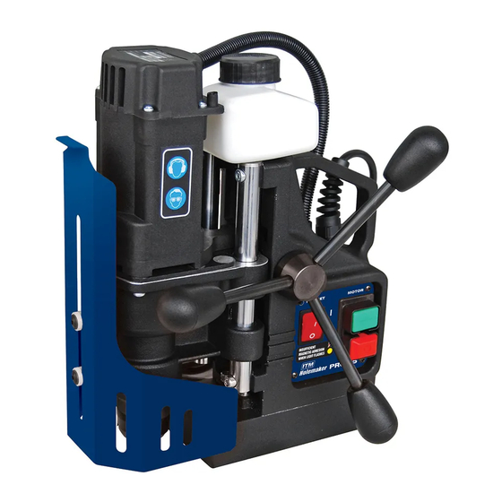
HMPRO35 OPERATOR’S MANUAL PRO-36 1.4. Dimensions 179 mm (7″) 314 mm (12.4″) 1.5. Design Cooling system bottle Bottle valve lever Feed shaft Carrying handle Motor START Spindle with arbor Chip guard Electromagnetic base Motor STOP Hole for a safety strap Electromagnetic base switch (MAGNET) This document is protected by copyrights. -
Page 6: Safety Precautions
HMPRO35 OPERATOR’S MANUAL PRO-36 2. SAFETY PRECAUTIONS 1. Before use, read this operator’s manual and complete a training in occupational safety and health. 2. Use only in applications specified in this operator’s manual. 3. Make sure that the machine has all parts and they are genuine and not damaged. 4. - Page 7 HMPRO35 OPERATOR’S MANUAL PRO-36 20. Do not use on surfaces that are rough, not flat, not rigid, or have rust, paint, chips, or dirt. 21. Use the safety strap to attach the machine to a stable structure. Put the strap through the hole in the machine body.
-
Page 8: Symbols
HMPRO35 OPERATOR’S MANUAL PRO-36 3. SYMBOLS Before using the machine, read the description of the following symbols. Warning against electric voltage Wear eye protection Wear ear protection Refer to instruction manual This document is protected by copyrights. www.itmtools.com.au Copying, using, or distributing without permission of PROMOTECH is prohibited. -
Page 9: Startup And Operation
HMPRO35 OPERATOR’S MANUAL PRO-36 4. STARTUP AND OPERATION 4.1. Installing and removing the annular cutter Unplug the power cord. Turn the handles to the right (1) to lift the motor. Use gloves to put the correct pilot pin into the cutter (2). Use a dry cloth to clean the spindle and the cutter. -
Page 10: Installing And Removing The Cooling System
HMPRO35 OPERATOR’S MANUAL PRO-36 4.2. Installing and removing the cooling system Turn the handles to lift the motor (1). Put the bottle on the machine (2). Attach the hose to the fitting (3). To remove the bottle, first detach the hose and lift the motor. Fig. -
Page 11: Preparing
HMPRO35 OPERATOR’S MANUAL PRO-36 4.3. Preparing Before use, clean steel parts, including the spindle, from anti-corrosion material used to preserve the machine for storage and transport. Attach the handles to the feed shaft. The machine can help the work of a left- handed person or in hard-to-reach places. - Page 12 HMPRO35 OPERATOR’S MANUAL PRO-36 Vertical drilling Inverted drilling CORRECT INCORRECT ✓ Horizontal drilling Fig. 3. Securing the machine from falling with the safety strap Turn the handles to the left to put the cutter above the workpiece. For vertical drilling, fill the cooling system bottle with coolant. Do not use only water as the coolant.
-
Page 13: Drilling
HMPRO35 OPERATOR’S MANUAL PRO-36 4.4. Drilling Press the green Motor START button to start the motor. Turn the handles to the left to put the cutter into the workpiece. When the cutter goes through the workpiece, the slug core is pushed out with a large force. -
Page 14: Replacing The Brushes
HMPRO35 OPERATOR’S MANUAL PRO-36 4.5. Replacing the brushes At intervals of 100 work hours, check the condition of the brushes. To do this, unplug the power cord and remove the cover (1). Next, remove the pressing plate (2), and then remove the brush holder (3) and the brush (4). If the brush is shorter than 5 mm (0.2″), replace the two brushes with new ones. -
Page 15: Wiring Diagram
HMPRO35 OPERATOR’S MANUAL 5. WIRING DIAGRAM Parts list PRO 36 v.4.17 www.itmtools.com.au... -
Page 16: Parts Breakdown
HMPRO35 OPERATOR’S MANUAL 6. PARTS BREAKDOWN Parts list PRO 36 v.4.17 www.itmtools.com.au... - Page 17 HMPRO35 OPERATOR’S MANUAL Parts list PRO 36 v.4.17 ITEM PART NUMBER DESCRIPTION Q-TY SZN-0212-10-02-00-1 POWER CORD 230V 3x1 WITH STRAIN RELIEF ASSY (AU) SPPRO3508 SPOKE HANDLE WITH KNOB ASSY PNL-0440-27-00-00-1 CONTROL PANEL ASSY - 230V KRP-0440-01-01-00-3 BODY ASSY RDK-0440-02-00-00-3 GEARBOX ASSY SLN-0440-03-00-00-5 MOTOR ASSY - 230V SPPRO3505...
- Page 18 HMPRO35 OPERATOR’S MANUAL Parts list PRO 36 v.4.17 ITEM PART NUMBER DESCRIPTION Q-TY SPPRO350312 MOTOR COVER PRS-000070 SEAL 25x37x7 SPPRO350212 GEAR RACK SRB-000111 HEX SOCKET HEAD CAP SCREW M6x18 SPPRO3509 BOTTOM SLEEVE SPPRO350704 CABLE GLAND WITH STRAIN RELIEF PG11 SPPRO3504 CHIP GUARD ASSY SPPRO3511 NYLON WASHER 8.1x14x3...
- Page 19 HMPRO35 OPERATOR’S MANUAL Cutter Type Features Diameter Available Cut Depth Available Applications Silver Series Metric • M2AL High speed steel • Universal shank • 12 to 65mm Metric • 25mm & 50mm • General purpose • Multi-cut geometry • Step hardened Silver Series Imperial •...
- Page 20 HMPRO35 OPERATOR’S MANUAL www.itmtools.com.au...
Need help?
Do you have a question about the HOLEMAKER PRO 35 and is the answer not in the manual?
Questions and answers